Model EQ10
Installation, Operation and Maintenance
Page 10 Rev. 11/30/2020
EQ10-IOM-Q.doc
OPERATION PROCEDURE
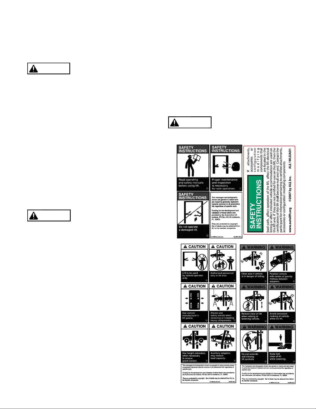
SAFETY NOTICES AND DECALS
This product is furnished with graphic safety
warning labels, which are reproduced on page 3
of these instructions. Do not remove or deface
these warning labels, or allow them to be
removed or defaced. For your safety, and the
safety of others, read and understand all of the
safety notices and decals included.
OWNER/EMPLOYER RESPONSIBILITIES
This lift has been designed and constructed according to
ANSI/ALI ALCTV standard. The standard applies to lift
manufactures, as well as to owners and employers. The
owner/employer’s responsibilities as prescribed by
ANSI/ALI ALOIM, are summarized below. For exact
wording refer to the actual standard provided with this
manual in the literature pack.
The Owner/Employer shall ensure that lift
operators are qualified and that they are trained in
the safe use and operation of the lift using the
manufacturer’s operating instructions; ALI/SM 93 -1,
ALI Lifting it Right safety manual; ALI/ST-90 ALI
Safety Tips card; ANSI/ALI ALOIM, American
National Standard for Automotive Lifts-Safety
Requirements for Operation, Inspection and
Maintenance; ALI/WL Series, ALI Uniform Warning
Label Decals/Placards; and in case of frame
engaging lifts, ALI/LP-GUIDE, Vehicle Lifting
Points/Quick Reference Guide for Frame Engaging
Lifts.
The Owner/Employer shall establish procedures
to periodically inspect the lift in accordance with the
lift manufacturer’s instructions or ANSI/ALI ALOIM,
American National Standard for Automotive Lifts-
Safety Requirements for Operation, Inspection and
Maintenance; and the employer shall ensure that
the lift inspectors are qualified and that they are
adequately trained in the inspection of the lift.
The Owner/Employer shall establish procedures
to periodically maintain the lift in accordance with
the lift manufacturer’s instructions or ANSI/ALIOIM,
American National Standard for Automotive Lifts-
Safety Requirements for Operation, Inspection and
Maintenance; and the employer shall ensure that
the lift maintenance personnel are qualified and that
they are adequately trained in the maintenance of
the lift.
The Owner/Employer shall maintain the periodic
inspection and maintenance records recommended
by the manufacturer or ANSI/ALI ALOIM, American
National Standard for Automotive Lifts-Safety
Requirements for Operation, Inspection and
Maintenance.
The Owner/Employer shall display the lift
manufacturer’s operating instructions; ALI/SM 93 -1,
ALI Lifting It Right safety manual; ALI/ST-90 ALI
Safety Tips card; ANSI/ALI ALOIM, American
National Standard for Automotive Lifts-Safety
Requirements for Operation, Inspection and
Maintenance; and in the case of frame engaging lift,
ALI/LP-GUIDE, Vehicle Lifting Points/Quick
Reference Guide for Frame Engaging Lifts; in a
conspicuous location in the lift area convenient to
the operator.
IMPORTANT SAFETY INSTRUCTIONS
When using your garage equipment, basic safety
precautions should always be followed, including
the following:
1. Read all instructions.
2. Care must be taken as burns can occur from
touching hot parts.
3. To reduce the risk of fire, do not operate
equipment in the vicinity of open containers of
flammable liquids (gasoline).
4. Keep hair, loose clothing, fingers, and all parts
of body away from moving parts.
5. Use only as described in this manual. Use only
manufacturer’s recommended attachments.
6. ALWAYS WEAR SAFETY GLASSES.
Everyday eyeglasses only have impact resistant
lenses; they are not safety glasses.
SAVE THESE INSTRUCTIONS