EKKO EK13 User manual

Service Manual
Counter Balanced Stacker
EK13, EK14, EK13S, EK14S
WARNING
You must understand the operation instructions in this manual
before using it.
Attention:
•Please check the last page of this document and all
the current product type identification on the name
plate.
•Keep it for future use

1
Table of Contents
1. Maintenance List .........................................................................................................................2
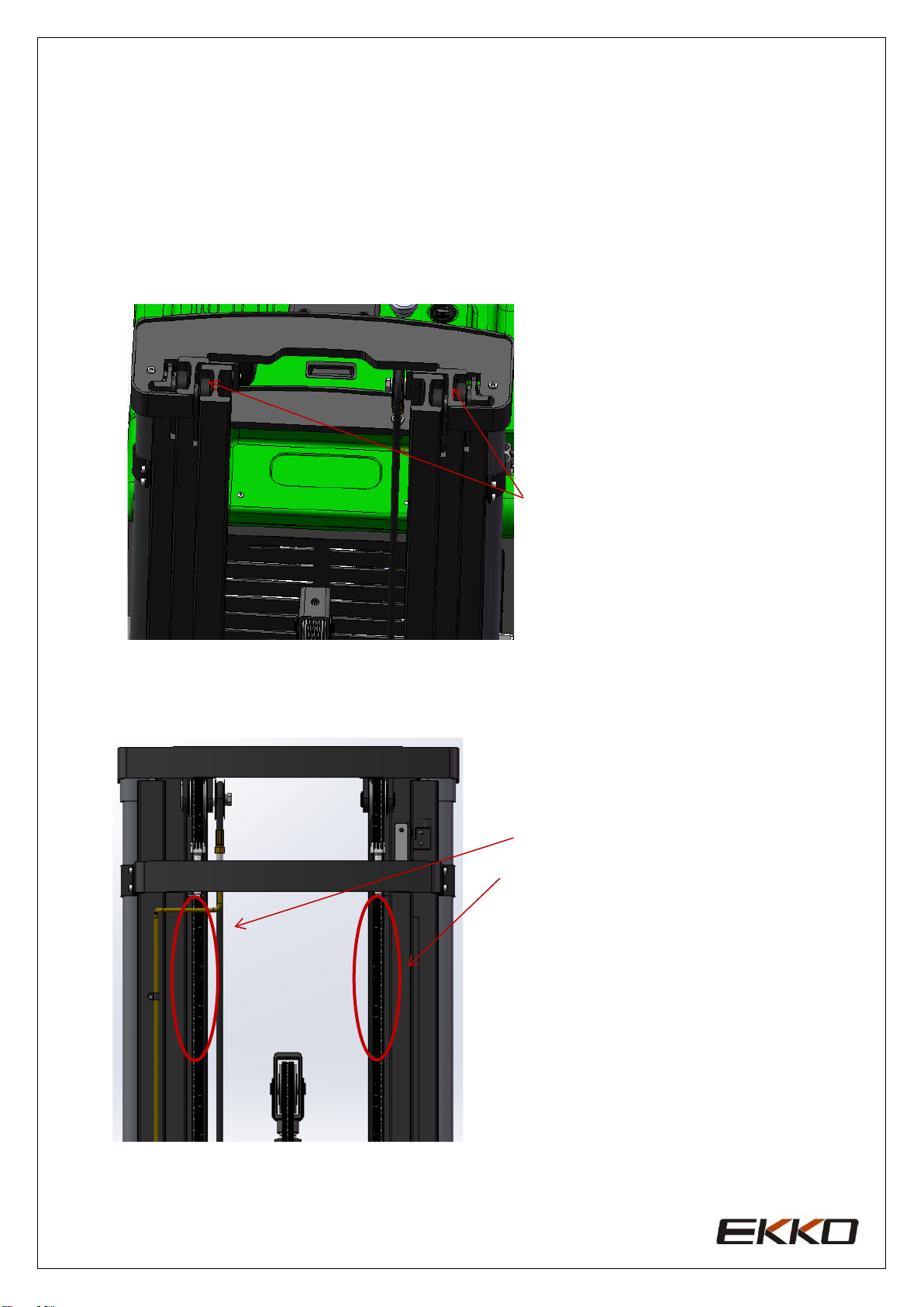
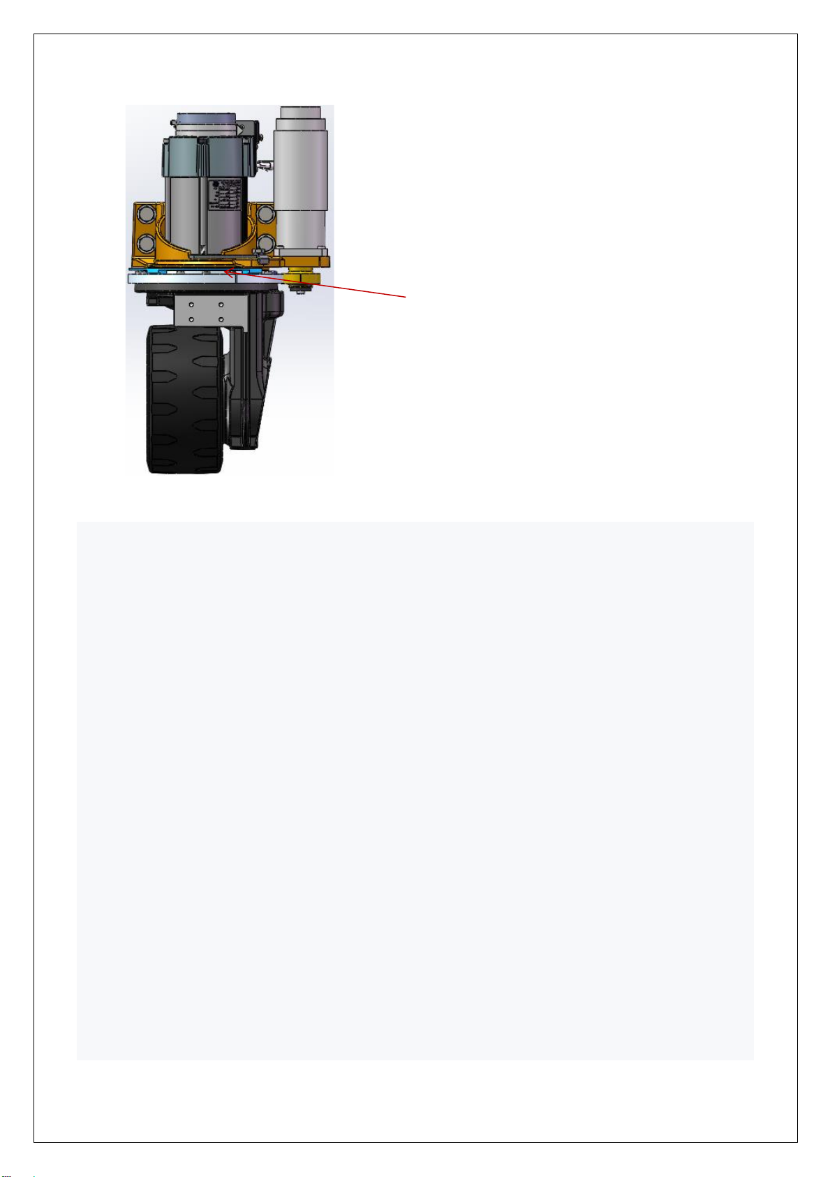
A. Overview of main components ................................................................................................2
B. Lubrication point.......................................................................................................................4
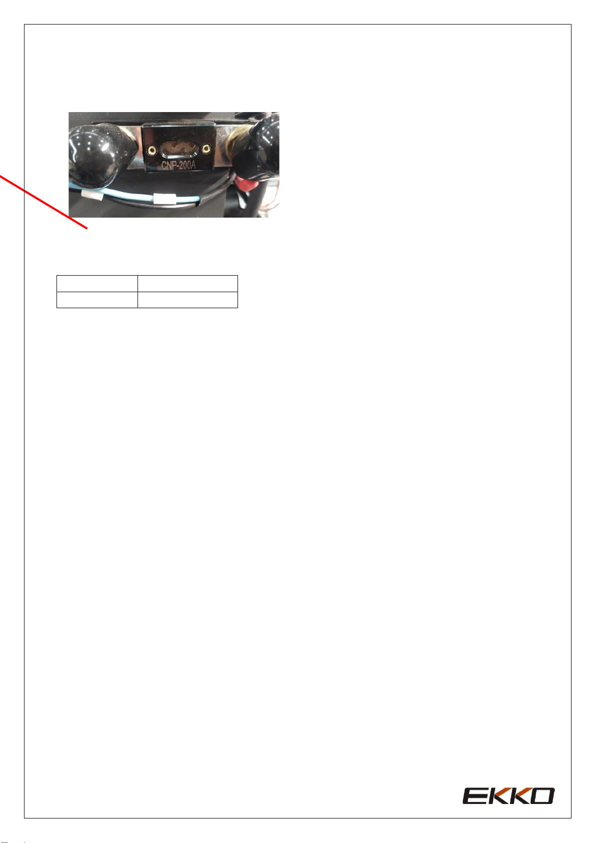
C. Check the fuse...........................................................................................................................6
2. Fault Analysis ...............................................................................................................................7
A. Common fault analysis..............................................................................................................7
B. The fault code display ...............................................................................................................8
c. Methods for troubleshooting common faults ............................................................................9
3. Wiring/circuit Diagram...............................................................................................................14
A. Schematic diagram and wiring diagram..................................................................................14
B. Hydraulic circuit .....................................................................................................................15
4. Disassembly of main parts..........................................................................................................16
A. Removal of handle assembly ..................................................................................................16
B. Removal of electric control component ..................................................................................18
C. Hydraulic assembly removal...................................................................................................20
D. Arm guard assembly removal .................................................................................................21
E. Mast assembly.........................................................................................................................22
F. External door frame removal ..................................................................................................24
G. Middle door frame removal ....................................................................................................26
H. Inner door frame removal .......................................................................................................27
I. Electrical assembly .................................................................................................................28
5. CURTIS handhold unit ...............................................................................................................30

2
1. Maintenance List
A. Overview of main components
List 1: Maintenance List
Interval
(month)
1
3
6
12
The hydraulic system
1
Check the hydraulic cylinder, piston for damage noise and leakage
•
2
Check hydraulic fittings and tubing for damage and leakage
•
3
Check hydraulic oil level and refill if necessary
•
4
Refill with hydraulic fluid (12 months or 1500 working hours)
•
Mechanical systems
5
Check the fork for deformation and cracks
•
6
Check the base for deformation and cracks
•
7
Check that all screws are properly fastened
•
8
Inspect door frame and chain for corrosion, deformation or damage and
replace if necessary.
•
9
Check gear box for noise and leakage
•
10
Check wheel for deformation and damage and replace if necessary
•
11
Lubricated steering bearing
•
12
Check and lubricate the pivot points
•
13
Lubricating grease nozzle
•
14
If the protection and/or protection plate is damaged, replace it
•
Electric System
15
Check for damaged wires
•
16
Check electrical connections and terminals
•
17
Test emergency stop switch function
•
18
Check the electric drive motor for noise and damage
•
19
Detection display
•
20
Check that the correct fuse is used and replace it if necessary
•
21
Check the buzzer
•
22
Check the current contactor
•
23
Check frame for leakage (insulation test)
•
24
Check accelerator function and wear
•
25
Check the electrical system driving the motor
•

3
Driving system
26
Check braking performance
•
Storage Battery
27
Checking the Battery voltage
•
28
Clean and grease terminals and inspect for corrosion and damage
•
29
Check whether the battery casing is damaged
•
Charger
30
Check whether the main power cable is damaged
•
31
Check the startup protection program during charging
•
Function
32
Check the buzzer
•
33
Check the air gap of the electromagnetic brake
•
34
Test emergency brake function
•
35
Test reverse braking and regenerative braking functions
•
36
Check steering function
•
37
Check lifting and descending functions
•
38
Check whether the key switch is damaged and functional
•
39
Detection speed limit switch (lifting height >~400mm)
•
synthesize
40
Check all labels for clarity and completeness
•
41
Check that the guard plate and/or guard are not damaged
•
42
Check casters, if worn height adjustment or replacement
•
43
Run a trial run
•

4
B. Lubrication points
-Lubricate marked points according to maintenance list.
-Required grease specification: DIN 51825 standard grease.
Chain lubrication
Door frame
track
lubrication

5
A. Check and correct electrolytes
The electrolyte density is based on 25℃.Therefore, when measuring, if the temperature of the
electrolyte is higher or lower than 25℃, every 1℃ higher, should be measured from the actual
density value plus 0.0007; On the contrary, lower than 25℃, every 1℃, should be minus 0.0007;If
the temperature difference is large.
Can be corrected by pressing the following formula:
Standard temperature of electrolyte (25℃) Density is converted according to the following formula:
D25 = Dt + 0.0007(T-25)
D25 -- electrolyte density at 25℃
Dt -- T ℃ measured electrolyte density
T -- Temperature of electrolyte when measuring density
Under the condition of normal working of charging function, the density of 1.26±0.005(25℃)
temperature below 30℃ sulfuric acid electrolyte into the battery, liquid level requirements higher
than the protection plate 15 ~ 25 ㎜.
Leave the battery to rest for 3-4 hours, no more than 8 hours. Initial charging can be carried out
only when the liquid temperature drops below 35℃.If the electrolyte level drops after standing, the
electrolyte should be replenished.
The discarded batteries must be recovered and stored in the specified environmental protection area
or the specified waste disposal area in accordance with the local laws and regulations, and the work
must be carried out by qualified professional companies.
Axle lubrication

6
C. Check the fuse
List 2: Fuse specification
Specification
Fuse 1
200A
200Afuse

7
2. Fault analysis
If the vehicle continues to malfunction, follow the instructions of the manual.
A. Common fault analysis
Hand and foot break common faults and troubleshooting methods
Fault
Cause
Maintenance
Vehicles cannot move
The battery connector is not connected
Check the battery connector and
connect it if necessary
The electric lock switch is in "OFF"
position
The electric lock switch is placed in
the "0" position
The emergency stop switch is not on
Turn on the emergency stop switch
Battery running out
Check the charging status of the
battery and recharge it if necessary
The forklift is charging
Interrupt charging process
Fuse damage
Check fuse
Cargo cannot be lifted
The vehicle is not running
Follow the procedure listed in the
"Vehicle cannot Move" fault
There's too little hydraulic fluid
Check hydraulic oil
Fuse damage
Check fuse
Load overweight
Note rated load
The lift micro switch is in bad contact or
damaged
Check fuse
Goods cannot be
lowered
You can't stop when
you go up
Dirty oil clogs the control valve
Check the hydraulic oil and clean the
control valve, replace the hydraulic oil
if necessary
The descent solenoid valve is not open or
damaged
Check the drop solenoid or replace it
Moving in one
direction
The lifting micro switch is damaged
Cut off the power supply and replace
the lifting micro switch
Traffic moves slowly
Contact between micro switch and
connecting cable is not good
Check the micro switch and
connecting cable in the control handle
The vehicle started
suddenly
The battery power is low or the
corresponding cable is in poor contact
Check the battery indicator and
corresponding cables
Goods cannot be
lowered
Controller damage
Replacing a Controller
Control forward and backward handle is
not reset
To restore or replace

8
If the vehicle is malfunctioning and cannot be operated outside the work area, lift the vehicle up, place a load
handling device under the vehicle and secure the vehicle, then remove the vehicle out of the channel.
B. The fault code display
Table 4:1212P fault codes
Programmer display
code
The fault phenomenon
fault diagnosis
BATTERY DISCONNECT
FAULT
4.5
Battery don't answer
1) The battery is not connected
BRAKE OFF FAULT
3.4
Brake closing fault
2) Poor contact of battery end
BRAKE ON FAULT
3.2
Brake opening failure
1) Electromagnetic brake coil short circuit
CURRENTSENSE FAULT
4.1
Current detection fault
2) Electromagnetic brake drive open circuit
EEPROM CHECKSUM
FAULT
4.3
EEPROM failure
1) Electromagnetic brake coil open
HARDWARE FAILSAFE
4.2
Motor voltage is out of
range
2) Electromagnetic brake drive short circuit
HPD FAULT
3.5
HPD fault
1) Short circuit of motor or motor wiring
MAIN FAULT
2.3
The main contactor is
faulty
2) The controller is faulty
MAIN OFF FAULT
2.1
Main contactor coil drive
'off' failure
1) EEPROM is faulty or invalid
MAIN ON FAULT
2.4
Main contactor coil drive
'on' failure
1) Motor voltage cannot match accelerator
input
OVERVOLTAGE FAULT
1.5
Battery voltage is too high
2) Short circuit of motor or motor matching
ring
PRECHARGE FAULT
3.3
Pre-charge failure
3) The controller is faulty
SPEED POT FAULT
1.3
The speed limiting
potentiometer is faulty
1) Accelerator, key switch, promotion or
prohibition
THERMAL FAULT
1.1
Over/under temperature
cut-off
Input several actions out of order
THROTTLE FAULT
1.2
Potentiometer slip end or
low
2) Wrong adjustment of accelerator
UNDERVOLTAGE
FAULT
1.4
The terminal voltage is out
of range
1) Main contactor adhesion or open

9
C. Methods for troubleshooting common faults
1、Code 4.5 Battery is not connected
Check whether the fastening of cable terminals of the car body is loose, as shown
2. Use a multimeter to measure the monomer voltage of the battery with load. The specific operation is shown as
follows:
Cell with load measurement, cell voltage drop should be
When it's between 2 and 3V
•
Check whether the cable connection (including other secured
parts) is loose
•

10
1、Codes 3.4 and 3.2 Electromagnetic brake line problems, or electromagnetic brake failure
Use a multimeter to measure the resistance of the two cores on the controller to the plug-in. The specific
operations are as follows:
Code 4.1 Motor or motor line short circuit or controller failure
1. Remove the motor brake disc (the brake line is still connected), connect the motor M1 M2 directly to the
positive and negative poles of the battery, observe whether the motor rotates normally, if not, the motor will fail.
2. If the motor turns normally, the controller should be replaced.
Operation sequence failure in 3.5 and 3.1
1, interlock switch under normal circumstances, use a multimeter to measure the controller 14 core plug-in
between J1-6 and the negative pole, when the handle rod is in the switch working area, there is about 24V voltage.
If not, check the interlock switch. For example, check whether the interlock switch is normal and whether the
signal cable of the switch is connected to the controller.
Normally, it should be
about 40 ω. If no
resistance is displayed,
there is a problem with
the brake line or a short
circuit of the brake coil.

11
4.2 Motor voltage cannot match accelerator input, motor or motor ring short circuit and controller fault,
troubleshooting operations are shown as follows:
If the voltage change of accelerator is normal, replace the controller
Six, determine the controller fault
Unplug the accelerator docking plug, if the controller is still reported fault after powering on (in addition to the
above faults), the controller is faulty.
7. If the controller fault is steady on and there is no walking, the troubleshooting steps are as follows:
1. Measure whether there is voltage output of accelerator 0--5V (between J1-1 and negative electrode)
2. Short-circuit j1-6 on the 14-core plug of the controller with line 7 on the 5-pin. After restarting, turn the
accelerator to see if there is a walk.
3. The brake is locked, remove the brake (the brake line is still connected), restart and turn the accelerator to check
whether it is normal.
4, remove the motor brake disc (brake line is still connected), connect the motor M1 M2 directly to the battery
positive and negative poles, observe whether the motor is normal rotation, if not, the motor failure.
5. If all the above tests are normal, judge the controller problem.
No lifting down or automatic cylinder drop, troubleshooting method is as follows
Switch the multimeter to 20V DC, insert the pen j1-1
(accelerator 0-5V speed signal) and 2 (negative pole)
respectively, turn the accelerator after power on, and
observe whether the multimeter reading has 0-5V
voltage linear change

12
1、
Press down button, down solenoid valve signal red light should be steady on
1. If the vehicle cannot be lifted normally, for example, the original 2800-3300lbs vehicle can only
be lifted less than 2000lbs, then the oil pump pressure can be adjusted, but this operation must be
carefully, if the hydraulic pressure is adjusted so that the vehicle load exceeds the rated, it may make
the frame deformation.
If the cylinder drops after lifting to the top,
check whether the red mark of the drop
solenoid valve is loose. If not, clean or replace
it.
Here is the coil wiring of the lifting contactor (line numbers are
2 and 15). After powering on, press the lifting button to measure
whether there is a voltage of about 24V at these two places. If
so, and there is no sound of pulling on the contactor, then the
contactor is faulty. If there is no 24V voltage, then line 15 at the
measuring handle is connected to line 15 at this point.
The red light is the signal light of the
descending solenoid valve. If the light is not
on, measure whether line 16 is connected to
the handle connection.

13
Specific operation are as follow:
The wrench unscrewed the pressure nut.
Using an inner hexagon wrench, adjust the pressure.

14
3. Wiring/circuit diagram
A. Schematic diagram and wiring diagram

15
B. Hydraulic circuit
Hydraulic oil inspection
Appearance
Odor
Condition
Results
Clear not discoloration
good
good
can be used
color transparency
good
with other oil mix
check viscosity, if qualified can
continue to use
Color changes like milk
well
mixed with air and water
to separate moisture or replace
hydraulic fluid
The color becomes dark brown
not
good
for oxidation
replacement of hydraulic oil
Clear color but small black spots
good
mix with other particles
can be used after filtering
Hydraulic circuit

16
4. Disassembly of main parts
A. Removal of handle assembly

17
NO.
Code
Name
Quantity
Remark
1
SL20GA-01.6.3
Electromagnetic brake
magnetic sensor assembly
1
2
GB/T 70.1-2000
Hexagon socket head screws
M6×150
4
3
SL20GA-01.6.7
Ac motor
1
4
GB/T 70.1-2000
Hexagon socket head screws
M8×20
8
5
GB/T 93-1987
Elastic washer
Φ8
24
6
GB/T 70.1-2000
Hexagon socket head screws
M12×50
6
7
GB/T 93-1987
Elastic washer
Φ12
6
8
ZD-ZV21-500-
001
reducer
1
9
GB/T 95-2002
Flat washer
Φ12
6
10
TY-01.40
Proximity switch PM12-
04N
1
11
SL20GA-01.6.6
The installation of
1
12
GB/T 70.1-2000
Hexagon socket head screws
M6×20
1
13
E10GL-01.9.1
Drive base plate (1)
1
14
GB/T 70.1-2000
Hexagon socket head screws
M8×40
12
15
SL20GA-01.6.4
Giant rotary bearing
1
16
ZD-ZV21-BJL-
001
Wheel drive
Φ248
1
17
Big wheel nut
5
18
E10GL-01.9.2
Drive base plate (2)
1
19
TY-01.8
Steering motor
0.2KW
1
20
GB/T 70.1-2000
Hexagon socket head screws
M8×25
4

18
B. Removal of electric control component
NO.
Code
Name
Specification
Quantity
REMARK
1
GB/T 70.1-2000
Hexagon socket head screws
M10×25
2
2
GB/T 93-1987
Elastic washer
Φ10
2
3
SL20GA-
01.10.6
The cover plate
1
4
GB/T 70.2-2000
Hexagon socket flat round
head screws
M8×16
2
5
SL20GA-
01.10.1.4
The silicone tube
1
6
SL20GA-
01.10.1.2
pin
1
7
SL20GA-
01.10.1.3
screw
1
8
E10GL-02.1
Upper casing welding
1
9
GB/T 41-2000
Hexagonal nut
M10
1
10
GB/T 70.1-2000
Hexagon socket screw
M10×30
2
11
E10GL-02.2.2
Spring support
1
12
E10GL-02.2.4
Adjust the screw
1
13
CL10.10.3-3
spring
2

19
14
E10GL-02.2.3
Spring seat
1
15
E10GL-02.2.1
Casing welding
1
16
SL20GA-
01.10.3
Steering sensor
1
17
SL20GA-
01.10.1.7
Mounting plate
1
18
TY-01.7
Micros witch RV-166-1C25
1
19
GB/T 70.1-2000
Hexagon socket screw
2
20
GB/T 70.2-2000
Hexagon socket flat round
head screws
M5×16
2
21
SL20GA-
01.10.7
Outer cover plate
1
22
TY-01.12
handle T606-1
1
23
GB/T 70.1-2000
Hexagon socket head screws
M6×25
4
24
GB/T 93-1987
Elastic washer
Φ6
4
25
SL20GA-
01.10.04
Mounting plate welded
1
26
SL20GA-
01.10.8
pin
1
27
TY-02.2
Composite sleeve with
shoulder φ 28 x φ 20 x φ 18
x 16
2
28
GB/T 70.1-2000
Hexagon socket head screws
M8×40
1
29
SL20GA-
01.10.12
spacer
1
30
SL20GA-
01.10.5
The handle bar
1
31
SL20GA-
01.10.02
Air spring assembly
1
32
SL20GA-
01.10.11
Cover plate
1
33
GB/T 70.3-2000
Hexagon socket countersunk
head screws
M5×12
4
34
GB/T 879.2-
2000
Elastic cylindrical pin
Φ5×45
1
Other manuals for EK13
1
This manual suits for next models
3
Table of contents
Other EKKO Lifting System manuals
Popular Lifting System manuals by other brands

Golden
Golden Tornado 8-CYLINDER installation manual

Vestil
Vestil D-NS-100-LD manual

Eclipse Magnetics
Eclipse Magnetics Ultralift E ULE0100 Operation and maintenance manual

Beta
Beta 3025/PF Instructions for use

Golf-Lift
Golf-Lift GL-TL GOLF LIFT Installation and owner's manual

IMER INTERNATIONAL
IMER INTERNATIONAL EASY UP 5 SP Translation of the original instructions