Smith Water 700 Programming manual
MODELS 700, 900, AND 950
WATER SOFTENERS
OWNER’S MANUAL AND INSTALLATION GUIDE
VERSION 1.0 INTERNATIONAL

Owner’s Manual and Installation Guide 11/13/2020 2
10 Year Limited Warranty
To Whom Warranty Is Extended
This warranty is issued to the original owner at the original location
site and is not transferable to other sites or to subsequent owners
of the system.
Coverage
This limited warranty covers the Hague Quality Water International
system delivered to the original owner at the original location when
the system is purchased for personal, family, or household use. It
is intended to cover defects occurring in workmanship or materials
or both.
Warrantor’s Performance and Length of Limited Warranty
A.O. Smith Water Treatment (North America), Inc. warrants that
upon receipt from the original owner of any mechanical or
electronic part which is found to be defective in materials or
workmanship, A.O. Smith Water Treatment (North America), Inc.
will repair or replace the defective item for 3 years from date of
original installation. Media is not warranted.
A.O. Smith Water Treatment (North America), Inc. further warrants
that upon receipt from the original owner of any Hague Quality
Water International media tank/main control valve, brine cabinet,
found to be defective in material or workmanship, A.O. Smith
Water Treatment (North America), Inc. will repair or replace the
defective item for 10 years from date of original installation.
All defective parts must be returned, along with the equipment
serial number and date of original installation, to A.O. Smith Water
Treatment (North America), Inc. PREPAID, and replacement parts
will be returned by A.O. Smith Water Treatment (North America),
Inc. to the original owner FREIGHT COLLECT.
Further Exclusions and Limitations on Warranty
THERE ARE NO WARRANTIES OTHER THAN THOSE
DESCRIBED IN THIS WARRANTY INSTRUMENT.
This warranty does not cover any service call or labor costs
incurred with respect to the removal and replacement of any
defective part or parts. A.O. Smith Water Treatment (North
America), Inc. will not be liable for, nor will it pay service call or
labor charges incurred or expended with respect to this warranty.
In the event the water supply being processed through this product
contains sand, bacterial iron, algae, sulfur, tannins, organic matter,
or other unusual substances, then, unless the system is
represented as being capable of handling these substances in the
system specifications, other special treatment of the water supply
must be used to remove these substances before they enter this
product. Otherwise, A.O. Smith Water Treatment (North America),
Inc. shall have no obligations under this warranty.
This warranty does not cover damage to a part or parts of the
system from causes such as fire, accidents, freezing, or
unreasonable use, abuse, or neglect by the owner.
This warranty does not cover damage to a part or parts of the
system resulting from improper installation. All plumbing and
electrical connections should be made in accordance with all local
codes and the installation instructions provided with the system.
The warranty does not cover damage resulting from use with
inadequate or defective plumbing; inadequate or defective water
supply or pressure; inadequate or defective house wiring; improper
voltage, electrical service, or electrical connections; or violation of
applicable building, plumbing, or electrical codes laws, ordinances,
or regulations.
THIS WARRANTY DOES NOT COVER INCIDENTAL,
CONSEQUENTIAL, OR SECONDARY DAMAGES.
ANY IMPLIED WARRANTIES ON THE PRODUCT DESCRIBED
IN THIS WARRANTY WILL NOT BE EFFECTIVE AFTER THE
EXPIRATION OF THIS WARRANTY.
No dealer, agent, representative or other person is authorized to
extend or expand this limited warranty.
Some locations do not allow limitations on how long an implied
warranty lasts or the exclusion or limitation of incidental or
consequential damages, so the above limitations and exclusion
may not apply to you. This warranty gives you specific legal rights
and you may also have other rights which vary from location to
location.
Claims Procedures
Any defects covered by this warranty should be promptly
reported to:
A.O. Smith Water Treatment (North America), Inc.
4343 S. Hamilton Road
Groveport, Ohio 43125, USA
1-614-836-2115
When writing about the defects, please provide the original
owner’s name, telephone number, and original address, serial
number, and model number of the product, and date of purchase.
(This information should be listed in General Information at the
front of this manual.) A.O. Smith Water Treatment (North America),
Inc. reserves the right to replace defective parts with exact
duplicates or their equivalent.
For international sales, the supplying distributor is the
administrator of the warranty and should be the first point of
contact in the case of a claim.

Owner’s Manual and Installation Guide 11/13/2020 3
Contents
General Information .......................................................................................................................................................4
Getting Maximum Efficiency From the Appliance ..........................................................................................................5
Checklist Before Installation...........................................................................................................................................6
Precautions....................................................................................................................................................................7
Installation Steps and Start-Up Procedures ...................................................................................................................8
Bypass Valve ...............................................................................................................................................................15
Blending Valve............................................................................................................................................................. 15
Four-Button Icon Controller..........................................................................................................................................16
Setting the Controller ...................................................................................................................................................18
Advanced Customer Settings ...................................................................................................................................... 19
Assembly and Parts .....................................................................................................................................................21
Troubleshooting ...........................................................................................................................................................32
Water Conditioner Specifications–Metric .....................................................................................................................34
Water Conditioner Specifications–English ................................................................................................................... 35
Owner’s Manual and Installation Guide 11/13/2020 4
General Information
Congratulations on choosing a superior water treatment appliance! Soon you and your family will be
enjoying clean, clear water. Use this guide to attain the maximum benefit from your appliance. Keep it handy
for a reference guide and service log. If you have trouble with the operation of your appliance, see
Troubleshooting in the back of this manual or contact your distributor.
Please keep this guide and the serial number of your appliance.
A.O. Smith Water Treatment (North America), Inc.
4343 South Hamilton Road
Groveport, Ohio 43125, USA
1-614-836-2115
Warning: This appliance must be applied to potable water only.
Note: The manufacturer reserves the right to make specification and product changes without prior notice.
This manual is for installation, operation, and maintenance of the following international water conditioning appliance
models:
•Model 700
•Model 900
•Model 950
For Owner’s Reference
Date of Installation:
Model Number:
Serial Number1:
Hardness:
Iron:
pH:
Water Pressure:
Water Temp:
1The serial number is located underneath the valve cover.

Owner’s Manual and Installation Guide 11/13/2020 5
Getting Maximum Efficiency From the Appliance
To achieve the maximum benefit and performance from
this appliance, familiarize yourself with this manual and
the appliance.
1. The salt level should always be at least 1/3 full.
Refill the salt when the level drops below the water
level in the brine cabinet. A resin cleaner can be
used on a monthly basis. Clean white pellet,
cube-style, or solar salt is recommended. Do not
use rock salt.
Caution: Do not mix different types of salt.
2. You may switch to a salt substitute (such as
potassium chloride) in place of water conditioner
salt at any time. If potassium chloride is used in
place of salt, increase your hardness setting by
12% (multiply by 1.12). See Setting the Controller.
Caution: Do not use potassium chloride if your
water contains iron and/or manganese.
3. Should your electricity be off for any reason check
your controller for the correct time and reset as
necessary (See Advanced Customer Settings).
4. Program the appliance to regenerate at a time
when the water is not being used. If there is more
than one appliance, allow two hours between each
regeneration.
5. Protect the appliance, including the drain line, from
freezing.
6. Adhere to all operational, maintenance, and
placement requirements.
7. If dirt, sand, or large particles are present in the
water supply, the appropriate filter can eliminate
this problem.
8. If your appliance runs out of salt:
A. Open the salt lid and add salt.
B. Wait two hours, then press and hold the R
(Regenerate) button for 5 seconds.
C. Regeneration is complete after approximately
12 to 45 minutes, and the appliance is returned
to Service mode.
9. The appliance may be disinfected with 5.25%
sodium hypochlorite, which is the active ingredient
in household chlorine bleach. To disinfect the
appliance, add 118 mL (4.0 fluid ounces) of chlorine
bleach solution to the brine well of the brine cabinet.
The brine cabinet should have water in it. Start a
manual regeneration.
10. The bypass valve (located on the main control
valve) enables you to bypass the appliance if any
work is being performed on the appliance, well
pump, or plumbing. See Bypass Valve. Use Bypass
mode also for watering plants or lawns with
untreated water. If your appliance is equipped with
a bypass, turn the knob to the Bypass position to
bypass the appliance. Turn it to the Service position
to restore soft water to your home.
11. Before putting the appliance back in service after
work has been performed, turn on the nearest cold
water tap until water runs clear.
12. Inspect and clean the brine cabinet and air
check/draw tube assembly annually or when
sediment is present in the brine cabinet.
13. Model 950 contains redox media and activated
carbon media. These have a finite life and will
eventually require replacement if the advertised
performance capabilities of this device are to be
maintained.
14. This product is certified for barium and radium
226/228 reduction according to NSF/ANSI
Standard 44. Any Bypass system must be
completely in the Service position to ensure
maximum barium and radium 226/228 reduction.

Owner’s Manual and Installation Guide 11/13/2020 6
Checklist Before Installation
Refer to this checklist before installation.
Water Quality—If the water supply contains sand, sulfur, bacteria, iron bacteria, tannins, algae, oil, acid, or other unusual
substances, pre-treat the water to remove these contaminants before the water supply enters the appliance, unless the
appliance is represented as being capable of treating these contaminants in its specifications.
The appropriate water filter below can address these water shortcomings.
•Model 900IF (Iron Filter)–Reduces iron, manganese, hydrogen sulfide, and iron bacteria.
•Model 900CF (Carbon Filter)–Reduces chlorine taste and odor.
•Model 900NF (Acid Neutralizing filter)–Adjusts low pH water to a non-corrosive state.
Iron—A common problem found in many water supplies is iron. It is important to know what type of and how much iron is
in the water supply.
Iron Type
Description
Ferrous Iron* (sometimes
called clear water or
dissolved iron)
Only type of iron that can be treated with a water softener
Ferric Iron
Insoluble and the particles can eventually foul a resin bed. It should be filtered out before the
water reaches the softener
Organic Iron or Bacterial
Iron
Attached to other organic compounds in the water. Additional treatment is needed to remove
this type of iron
Colloidal Iron
Not dissolved, yet stays in suspension. A softener cannot remove this type of iron
* If the water supply contains ferrous iron, a commercially available resin bed cleaner should be used every six months. Follow the instructions on
the container. You should also increase your water hardness setting by 86 mg/L (5 grains per gallon) for every 1 mg/L (1 ppm) of ferrous iron.
Water Characteristics—Models 700, 900, and 950 require a pH of 7 or above to function properly. An iron test to
determine iron levels is also necessary. The 900-NF Acid Neutralizing Filter adjusts pH levels of 6.3 or above.
Water Hardness—Double check hardness of water with test strips, if provided, to verify that your appliance is right for
the job.
•Model 700 will condition water for up to 1,197 mg/L (70 grains of hardness per gallon).
•Model 900 will condition water for up to 1,539 mg/L (90 grains of hardness per gallon). (See Specifications.)
•Model 950 is FOR MUNICIPALLY-SUPPLIED WATER without iron. Model 950 will condition water up to 599 mg/L
(35 grains of hardness per gallon).
Water Pressure—Not less than 1.4 bar (20 psi) or greater than 8.3 bar (120 psi) constant. If water pressure exceeds
4.8 bar (70 psi), a pressure regulator is recommended.†
Water Supply Flow Rate—A minimum of 7.6 L (2.0 gallons) for the 700 and 900 models to 11.4 L (3 gallons) for the
950 model per minute or equal to the backwash flow rate of the particular model is recommended. For the purposes of
plumbing sizing, only the rated service flow rate and corresponding pressure loss may be used. Prolonged operation of a
water conditioner at flow rates exceeding the tested service flow rate may compromise performance.
Water Temperature—Not less than 4°C (40°F) or greater than 49°C (120°F).
Drain—Drain the appliance to an appropriate drain, such as a floor drain or washer drain that will comply with all
applicable plumbing codes. To prevent back-siphoning, provide an adequate air gap or a siphon break. See Installation
Steps and Start-Up Procedures.
Electricity—The transformer supplied is for a standard 115 volt, 60-cycle AC outlet for locations in North America or 220
volt, 50-cycle AC outlet for locations outside of North America.
†Applies to U.S. plumbing codes. Check the plumbing codes of your country.

Owner’s Manual and Installation Guide 11/13/2020 7
Precautions
Do
1. Comply with all applicable building, plumbing, and electrical codes.
2. Test your water quality with the strips, if provided. Optionally, obtain a report on your water’s quality.
3. Install the appliance before the water heater.
4. Install the appliance after the pressure tank on well-water installations.
5. Examine the inlet line to ensure water will flow through it freely and that the inlet pipe size is correct. For well water
with iron, the recommended minimum inlet pipe size is 3/4-inch I.D. and for municipal water the recommended
minimum inlet pipe size is 1/2-inch I.D.
6. Install a pressure-reducing valve if the inlet pressure exceeds 4.8 bar (70 psi).
7. Install a gravity drain on the cabinet.
8. Secure the drain line on the appliance and at the drain outlet. See Installation Steps and Start-Up Procedures.
9. Allow a minimum of 2.4 to 3 m (8 to 10 feet) of 3/4-inch pipe from the outlet of the appliance to the inlet of the water
heater.
Do Not
1. Do not install if checklist items are not satisfactory. See Checklist Before Installation.
2. Do not install if the incoming or outlet piping water temperature exceeds 49°C (120°F). See Specifications.
3. Do not allow soldering torch heat to be transferred to valve components or plastic parts when using the optional
copper adapters.
4. Do not overtighten the plastic fittings.
5. Do not plumb the appliance against a wall that would prohibit access to plumbing. See Installation Steps and
Start-Up Procedures.
6. Do not install the appliance backward. Follow the arrows on the inlet and outlet.
7. Do not plug the transformer into an outlet that is activated by an On/Off switch.
8. Do not connect the drain and the overflow (gravity drain) lines together.
9. Do not use to treat water that is microbiologically unsafe or of unknown quality without adequate disinfection before
or after the appliance.
10. Do not allow your appliance or drain line to freeze.
Note: A bacteriostasis claim does not mean that these devices will make microbiologically unsafe water safe to consume
or use.
Owner’s Manual and Installation Guide 11/13/2020 8
Installation Steps and Start-Up Procedures
The water softener is capable of treating a combination of undesirable constituents (such as iron, dirt, sediment, chlorine,
and/or lead) in water. See Specifications for the capabilities of your appliance. Install, set up, and use the appliance within
the operating limits outlined in this manual. Failure to comply with these specifications may decrease the effectiveness of
the backwash and cause control valve malfunction. The water softener, like any other appliance, requires correct
installation and setting for optimum performance.
Each water treatment appliance includes 2.4 m (8 feet) of drain line and a drain fitting.
Step 1
Prepare the Placement Area
A. Make sure the placement area is clean.
B. Turn off the electricity and water supply to the water heater. For gas water heaters, turn the gas cock
to “Pilot.”
C. Examine the inlet plumbing to ensure that the pipe is not plugged with lime, iron, or any other
substance. Clean or replace plugged plumbing.
Note: A minimum 3/4-inch pipe is required between the pressure tank and the appliance for the
appliance to function properly.
D. Make sure the inlet/outlet and drain connections meet the applicable plumbing codes.
E. Check the arrows on the bypass valve to ensure that the water flows in the proper direction.
See Bypass Valve.
Caution: Do not plumb the appliance in backward.
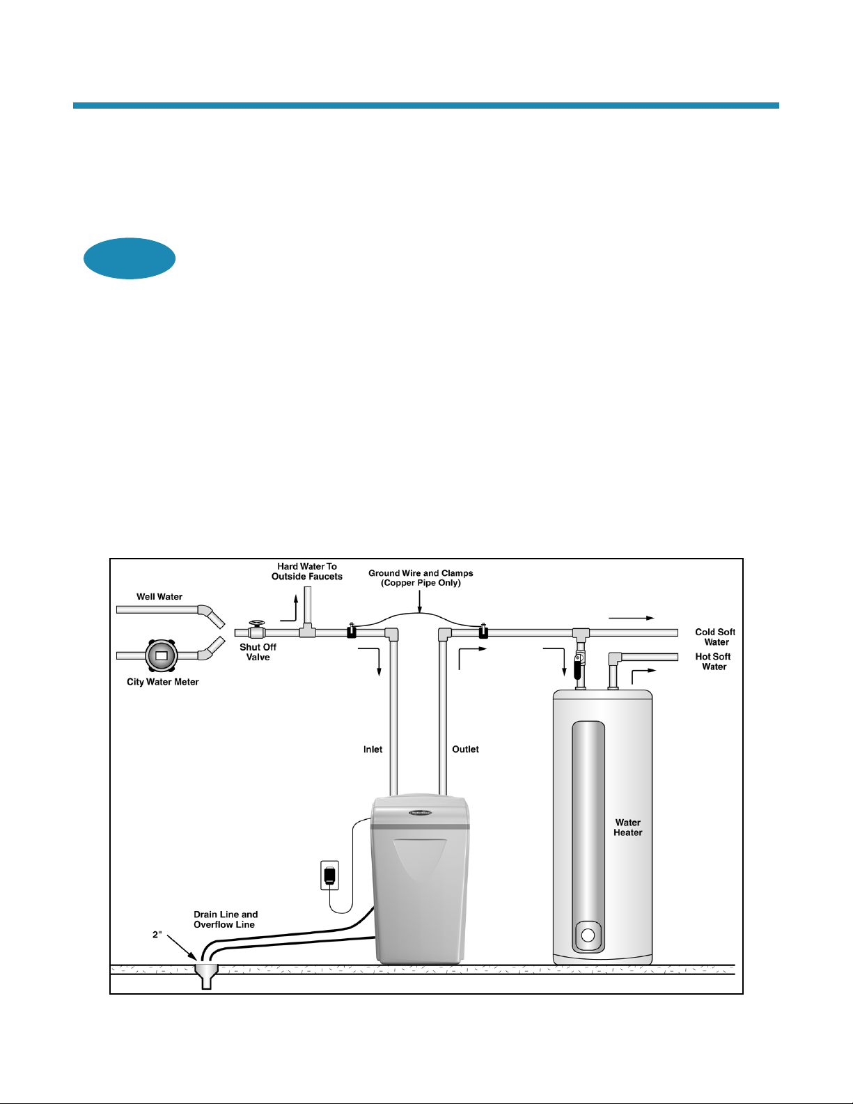
F. Place the appliance in the desired location using Figure 1 as a guide. The diagram in Figure 1
applies to basement, slab, crawl space, and outside installations.
Figure 1: Appliance Placement

Owner’s Manual and Installation Guide 11/13/2020 9
Installation Steps and Start-Up Procedures, Cont.
G. For most installations, install the appliance after the pressure tank and any water filter appliance or
water meter and before the water heater unless otherwise recommended.
Water Heaters: If less than 3 m (10 feet) of pipe connects the water treatment appliance(s) to the
water heater, install a check valve between the water treatment appliance and the water heater as
close to the water heater as possible. Ensure that the water heater has an adequately rated
temperature and pressure safety relief valve.
H. For outside installations, the appliance should be enclosed so it is protected from the weather.
Step 2
Test Your Water
A. Remove any packaging or installation materials from the brine cabinet.
B. Contact your water treatment specialist or obtain a report on your water’s quality. Optionally, use the
test strips if they have been provided.
Step 3
Turn Off Water Supply
A. Turn off the water supply.
B. Open the hot and cold water taps to depressurize the lines.
Step 4
Connect Water Lines
Your appliance may come with a built-in bypass valve.
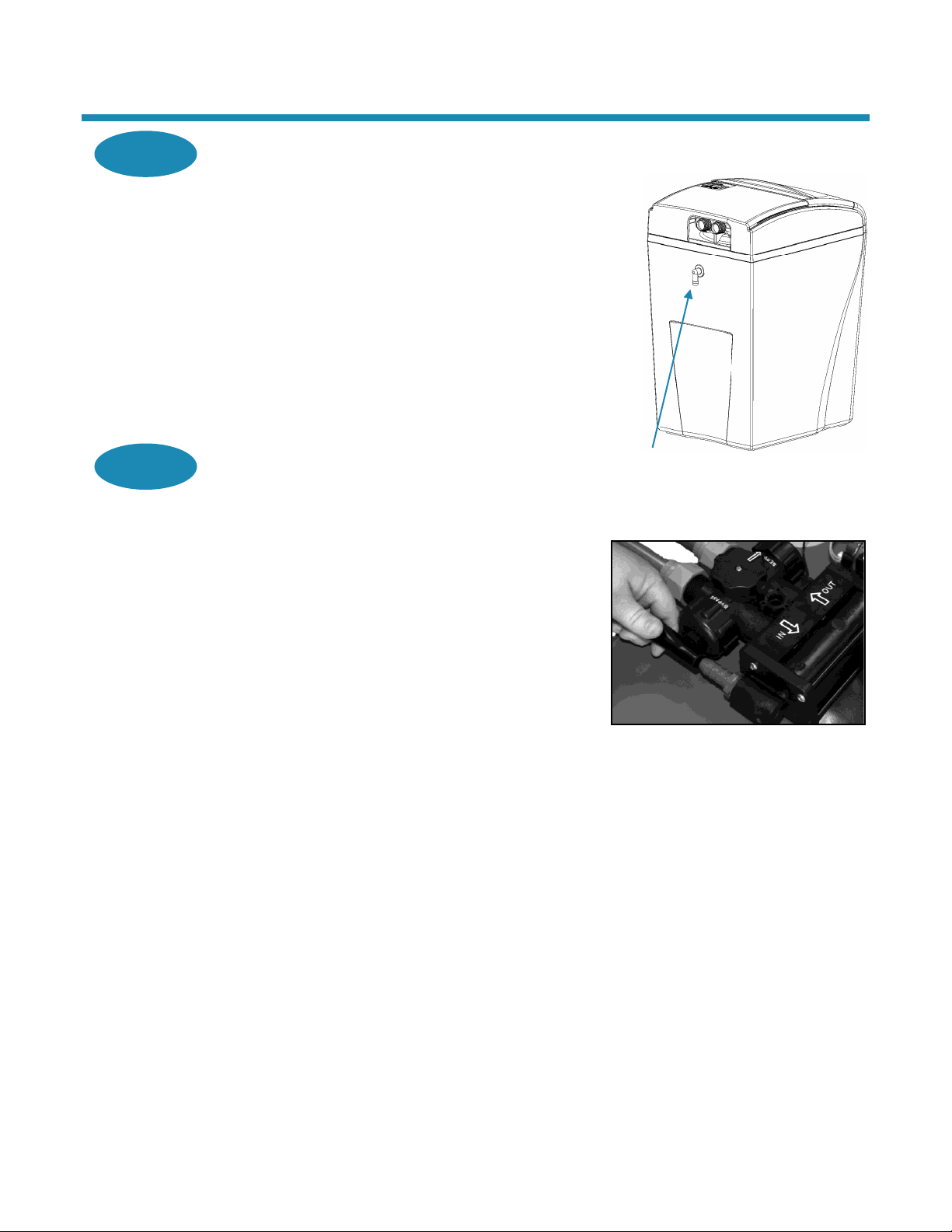
Step 4A: With Bypass Valve
A. Lift and remove the valve cover.
B. Remove any packaging or installation materials from the
brine cabinet.
C. Install connection fittings*. Connection fittings provide a
convenient, easy-to-use three-piece assembly for 3/4-inch
copper plumbing or 3/4-inch CTS CPVC plastic tubing.
Note: Teflon tape or plumber’s putty is NOT necessary and
should NOT be used with connection fittings.
D. Attach the water lines to the appliance in compliance with
all applicable building, plumbing, and electrical codes.
(See Figure 2.)
Caution: Do NOT overtighten the connections on the
plastic threads.
E. Check the arrows on the bypass valve to ensure that the
water flows in the proper direction.
Caution: Do NOT plumb your appliance in backward.
* Connection fittings are NOT included.
Figure 2: Connect Water Lines.*
Note the Bypass Valve Position.

Owner’s Manual and Installation Guide 11/13/2020 10
Installation Steps and Start-Up Procedures, Cont.
Step 4B: Without Bypass Valve (3/4-inch or 1-inch
Adapter) Using Copper Fittings
When preparing the male threaded fittings of the I/O
adapter, use the following guidelines to avoid damage to the
plastic pipe threads.
A. Wrap the threads three times with 1/2-inch wide Teflon
tape. Place each consecutive wrap on top of the
previous wrap.
B. To prevent tearing of the tape, use Teflon paste on the
first two male threads only. The paste lubricates the tape
and fills the small void areas that might exist between the
threads. When the joint is complete, there will be a small
bead of sealant at the fitting interface, which indicates a
properly joined connection.
C. Use a union with a threaded connection to facilitate
repair of potential leaks in soldered joints.
D. Prepare the copper tail assemblies in advance to enable
them to cool prior to final assembly. Advance preparation
and cooling will prevent heat damage to the plastic pipe
threads of the adapter.
E. Ensure that the copper tube is at least 10 cm
(4 inches) long.
F. Turn the fitting counterclockwise until you feel the
threads engage and then tighten to prevent cross
threading. Do NOT overtighten the fittings.
Caution: Do NOT allow heat from the torch to
transfer to the plastic valve component, which could
be damaged.
Figure 3: Plumbing Connections
Teflon Tape

Owner’s Manual and Installation Guide 11/13/2020 11
Installation Steps and Start-Up Procedures, Cont.
Step 4C: Without Bypass Valve (3/4-in or 1-in Adapter) Using Plastic (PVC/CPVC) Pipe
Joining Procedure
To ensure reliable joint integrity when using solvent cement for PVC/CPVC plumbing, follow these
recommendations:
A. Cutting—The pipe must be cut square to allow for the proper interfacing of the pipe end and the
fitting socket bottom. Use a wheel cutter, miter saw, or a ratchet shear for best results.
B. Deburring and Beveling—Use a knife, plastic pipe deburring tool, or a file to remove burrs from the
end of the pipe. Be sure to remove all burrs from the inside as well as the outside of the pipe.
Remove all loose plastic debris since it could clog the injector. All pipe ends should be beveled to
permit easier insertion of the pipe into the fitting. Failure to bevel the pipe end may cause a “wiping”
effect in the fitting where the cement is forced to the end of the fitting socket. This creates a
weak joint.
C. Test Dry Fit of the Joint—Tapered fitting sockets are designed so that an interference fit should
occur when the pipe is inserted about one-third to two-thirds of the way into the socket. Occasionally,
when pipe and fitting dimensions are at the tolerance extremes, it will be possible to fully insert dry
pipe to the bottom of the fitting socket. When this happens, a sufficient quantity of cement must be
applied to the joint to fill the gap between the pipe and fitting.
D. Inspection, Cleaning, and Priming—Inspect the inside of the pipe and fitting sockets and remove
dirt, grease, or moisture with a clean dry cloth. If wiping fails to clean the surfaces, use a chemical
cleaner. Check for possible damage such as splits or cracks and replace if necessary. Use purple
primer to penetrate and soften the bonding surfaces of the PVC or CPVC pipe and fittings. Proceed
without hesitation to the cementing procedure while the primed surfaces are still wet.
E. Application of Solvent Cement—Apply the solvent cement evenly and quickly around the outside of
the pipe while the primer is still wet. Apply a light coat of cement evenly around the inside of the fitting
socket. Do not allow excess cement to “puddle” in the fitting. Apply a second coat of cement to the
pipe end.
F. Joint Assembly—Working quickly, insert the pipe into the fitting socket and give a 1/4-turn of the
pipe or fitting while pushing toward the fitting stop. This action will evenly distribute the cement. Do
NOT continue to rotate the pipe or fitting after the stop has been reached. Hold the joint tightly
together for about 15 seconds to prevent the pipe from “creeping” out of the fitting. A good joint will
have sufficient cement to make a small bead all the way around the outside of the fitting hub. The
joint should not be disturbed immediately after the cementing procedure. Allow adequate time for the
joint to cure properly. Exact drying time is hard to predict because of environmental variables. Follow
the recommended joint curing times on the primer and cement container labels.
Owner’s Manual and Installation Guide 11/13/2020 12
Installation Steps and Start-Up Procedures, Cont.
Step 5
Connect Gravity Overflow Connection
The overflow line drains away excess water should the tank
fill with too much water or the appliance malfunction.
A. Attach the gravity overflow connection elbow and check
that it is in the down position. (See Figure 4.)
B. Connect 1/2-inch I.D. tubing (size cannot be reduced)
between the overflow fitting and a suitable floor drain,
laundry tub, or other suitable waste receptor. This tubing
is not supplied with the appliance. Ensure that the
overflow line ends at a drain that is at least 8 cm
(3 inches) lower than the bottom of the overflow fitting.
Maintain a minimum of 5 cm (2-inch) air gap. The
gravity line cannot be run overhead.
Step 6
Connect Drain Line
The drain line carries away the backwash water as part of
the regeneration cycle.
A. Screw the drain fitting (See Figure 5) into the drain end
cap until fewer than three threads are visible. To prevent
leakage, wrap the threads on the drain fitting three times
with 1/2-inch wide Teflon tape, or use plumber’s putty.
B. Connect the drain line to the drain end cap
(See Figure 5) with a minimum 5/8-inch I.D. tubing
(supplied). The size cannot be reduced.
C. Route the drain line to a floor drain, laundry tub, or other
suitable waste receptor. Maintain a minimum 5 cm
(2-inch) air gap between the drain line and the flood
level rim of the waste receptor to prevent
back-siphoning. This drain line should make the shortest
run to the suitable drain.
D. The drain line may be elevated up to 2.4 m (8 feet) from
the discharge on the appliance as long as the water
pressure in your system is 2.8 bar (40 psi) or more.
E. If the drain line is 7.6 m (25 feet) or longer, increase the
drain line to 3/4-inch I.D. The end of the drain line must
be equal to or lower in height than the control valve.
Caution: The drain line must not be kinked, crimped,
or restricted in any way.
Figure 4: Gravity Overflow Connection
Figure 5: Connect Drain Line
Gravity Overflow
Connection

Owner’s Manual and Installation Guide 11/13/2020 13
Installation Steps and Start-Up Procedures, Cont.
Step 7
Flush Lines
A. If your appliance is equipped with a bypass valve, place
the appliance in the Bypass position. (See Figure 6.)
B. Turn on the main water supply.
C. Open the nearest cold water faucet to flush the plumbing
of any excess soldering flux, air, or any other foreign
material.
D. Return the appliance to Service position.
Note: To prevent untreated water from entering your
home, avoid using water inside your home when the
appliance is in Bypass position. Remember to return the
appliance to Service position when you have finished
using untreated water.
Step 8
Check for Leaks
A. Close all faucets.
B. Check all lines and connections for leaks. If leaks are
found:
1. Turn off the main water supply.
2. Open a cold water faucet to depressurize
the lines.
3. Close the faucet to eliminate any siphoning action.
4. Repair all leaks.
5. Turn on the water supply.
6. If your appliance is equipped with a bypass valve,
place the appliance in the Service position to slowly
fill the media tank. (See Figure 7.)
7. Open a cold water faucet to purge air out of the
media tank.
8. Close the faucet and recheck for leaks.
Step 9
Plug in the Transformer
A. Connect the transformer power cord to the back of the
controller. (See Figure 8.)
B. Plug the transformer into an appropriate outlet.
C. Ensure that the outlet selected is NOT operated by an
On/Off switch.
Step 10
Set Up the Controller
A. Program the appliance controller. See Setting the
Controller.
Figure 6: Bypass Position
Figure 7: Service Position
Figure 8: Connect Power Cord

Owner’s Manual and Installation Guide 11/13/2020 14
Installation Steps and Start-Up Procedures, Cont.
Step 11
Add Water to the Brine Cabinet
A. Add 8 L (2 gallons) of water to the brine cabinet. After the first regeneration, the appliance will
automatically refill the correct amount of water into the brine cabinet.
B. Ensure the appliance is in Service position and your water supply is turned on.
C. Initiate a manual regeneration (see Setting the Controller) and inspect for proper operation. Allow the
appliance to draw water out of the brine cabinet until the air check/draw tube sets (8–10 minutes).
D. Press the R (Regenerate) button to advance to the Brine Refill (04) position. Let the tank fill with the
proper amount of water. The controller will then step the valve to the Home position.
Note: This initial startup is the only time you will add water to the brine cabinet. Do not add water at
any other time.
Step 12
Fill the Brine Cabinet With Salt
A. Fill the brine cabinet with salt. Use clean white pellet, cube-style, or solar salt. Do not mix pellet with
solar salt.
Note: Always keep the salt level above the water level. For convenience, completely fill the tank
when refilling with salt.
B. After you add salt, including adding it after the tank has run out of salt, wait two hours for saturated
brine before starting any regeneration.
Caution: Use of potassium chloride when iron and/or manganese are present in the raw water
supply is not recommended.
Step 13
Complete the Installation
A. If your appliance is equipped with a bypass valve, ensure that the appliance is in the Service position.
See Figure 7.
B. Ensure the water supply is on.
C. Turn on the electricity and water supply to the water heater. For gas water heaters, return the gas
cock to “On.”
D. Open a cold water tap and allow the appliance to flush for 20 minutes or until approximately 270 L
(72 gallons) have passed through the appliance. This procedure is required to meet NSF
requirements. Verify the flow rate on the controller, which indicates water flow. See Figure 11.
E. Adjust the blending valve if it is being used.
F. Replace the valve cover.
Owner’s Manual and Installation Guide 11/13/2020 15
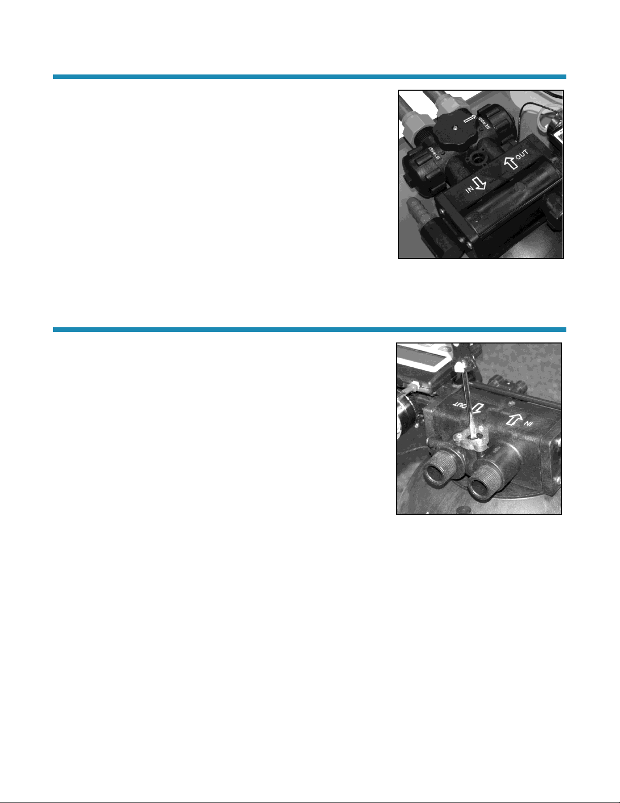
Bypass Valve
Your appliance may be equipped with a bypass valve. The bypass valve can
isolate the appliance should the appliance malfunction or leak. It can also
permit the use of untreated water for watering plants, shrubs, or lawns.
The bypass valve is located on the main control valve. See Figure 9. To
engage the bypass valve, turn the knob to the Bypass position. The
appliance will be bypassed and all water to the home is raw, untreated water.
To prevent untreated water from entering the home, water should not be
used inside the home when the appliance is in Bypass position. Ensure that
the appliance is returned to Service position when the appliance is repaired
or the use of untreated water is complete by turning the knob to Service.
To blend hardness back into the water using the bypass valve, turn the knob
slightly from the Service position toward the Bypass position.
Figure 9: Bypass Valve
Blending Valve
The 3/4-inch or 1-inch I/O may come with a blending valve.
In some situations, a blending valve may be desired. The amount of
hardness blended back into the water line is determined by the hardness of
the incoming water and the setting of the blending valve. Where extremely
hard water is present, the blending valve may only need to be “cracked”
open. Where the incoming water has relatively low levels of hardness, the
blending valve will need to be opened further.
The blending valve is located between the input and output connections on
the top of the 3/4-inch or 1-inch I/O adapter. See Figure 10. It is adjusted by
placing a flat blade screwdriver in the slot provided and turning clockwise to
open. Total movement of the blending valve from full closed to full open is
1/4 revolution. Precise setting of the blending valve will require “trial and
error” testing. The initial setting should be conservative. Because of the
blending valve’s ease of access and adjustment, you can increase or
decrease the setting according to your preference over a period of time.
Use of the blending valve is not recommended where objectionable
concentrations of ferrous iron or sediment are present. Because the blending
valve is mixing “raw” water with softened, any ferrous iron or sediment in the
“raw” water will also be blended and reintroduced into the softened
water line.
Note: If the appliance is installed for barium and/or radium reduction, the
blending valve must remain in the fully closed position at all times.
Figure 10: Adjusting Blending Valve

Owner’s Manual and Installation Guide 11/13/2020 16
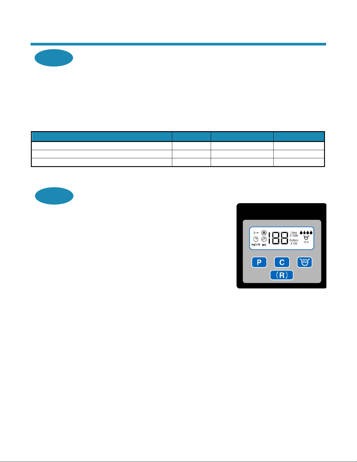
Four-Button Icon Controller
This appliance features a four-button icon controller with an LCD display. The controller can be used to view the
appliance’s status, perform regenerations, and change settings. The controller must be set up correctly for the appliance
to perform properly.
Note: Ensure that the bottom of the controller is firmly locked onto the four tabs on the top of the drive end cap assembly.
See Cabinet and Cover Assemblies diagram later in this manual.
Figure 11: Four-Button Icon Controller Showing All Possible Icons
Button
Function
(Program)
Used to set Customer Settings
(Change)
Used to change Customer Settings
(powerClean™)
(700 and 900 only)
Activates/deactivates the powerClean™ feature, which is a service/maintenance step for water supplies
that have an excessive amount of iron. “powerClean™” will display when this feature is activated. The
appliance will regenerate every other day with 2.3 kg (5 lb) of salt. Leave the powerClean™ feature on for a
minimum of two weeks. The frequent regeneration will eliminate iron buildup in the resin bed. The use of
salt with an iron cleaning agent or iron out cleaner is recommended for continuous use as a preventive
measure against iron fouling of the resin bed. Use this feature every six months as a part of your routine
maintenance procedure to ensure a long service life for your water treatment appliance
Note: To deactivate the powerClean™ feature, press the button.
(Regenerate)
Used when starting your water conditioner to start an immediate regeneration, or to restore capacity if you
run out of salt
To Start an Immediate Regeneration
1. Press and hold the R (Regenerate) button for about five seconds until the display flashes.
2. The appliance is in regeneration mode and will display the status of each cycle.
3. After all regeneration cycles are complete, the display will return to normal operating mode.
To Quickly Advance Through the Regeneration Cycles
(used when starting up or diagnosing the appliance only)
1. Press and hold the R (Regenerate) button for about five seconds until the cycle begins and the display
flashes the number of the next cycle.
2. The cycle position will display (for example, 01).
3. If the controller does not advance to the next cycle position after 20 seconds, press and hold the
R (Regenerate) button until the cycle number changes (about 2 seconds).
Each cycle can be advanced by pressing the R (Regenerate) button. Always wait until the cycle position
displays before advancing to the next cycle position.
LCD Display
Buttons

Owner’s Manual and Installation Guide 11/13/2020 17
Four-Button Icon Controller, Cont.
Controller Part
Function
LCD Display
Shows the status of the controller.
Demand Mode
The controller measures water usage and regenerates based on need, so you do not have to worry about
vacation settings or extra guests. The appliance will regenerate using only the necessary amount of water
and salt. If your power has been off, the appliance will retain programmed settings indefinitely.
Note: You should not need to change from Demand Mode.
Delay Mode
Allows regeneration at a specific time (for example, at 2 a.m.) when less water is typically being used.
Soft Water
Remaining Litres x
100 (or 1000) or
Gallons x 100
Shows the litres (or gallons) of soft water remaining until the next automatic regeneration. Typically, each
person in the household uses about 284 L (75 gallons) per day. Water remaining is in litres in hundreds or
thousands, depending on how much capacity is remaining, or gallons in hundreds.
For example: 33 = 3,300 or 33,000 litres (88 = 8,800 gallons).
Recharge/
Regeneration Status
Shows regeneration cycle numbers during regeneration. The read-out will flash with the cycle number. The
flashing regeneration numbers are:
First cycle
(01) First Backwash
Second and Third cycles
(02) Brine/Slow Rinse
Fourth cycle
(03) Second Backwash
Fifth cycle
(04) Brine Refill
Sixth cycle
(HO) Service (Briefly)
When regeneration is complete, the display shows the number of litres in hundreds or thousands (gallons in
hundreds) of soft water remaining. (See above.) Regeneration typically is complete in about 30 minutes.
waterMizerTM
Indicates that water is flowing through the appliance; the waterMizerTM indicator droplets light up across the
screen whenever water is being used; useful for checking for proper plumbing and leaks.
powerClean™
Displays when feature is activated. See powerClean™ Button.
96 h
If “96 h” is selected, the appliance will work no more than 4 days, (96 hours) without a regeneration. Default
is for “96 h” to be On.
Owner’s Manual and Installation Guide 11/13/2020 18
Setting the Controller
Step 1
Determine the Controller Hardness Setting Number
A. For municipal water, call the water department or your water treatment specialist, and they will
determine the hardness and pH of your water supply.
B. For well water, a water analysis should be taken in order to make sure your controller is set properly,
or obtain your hardness setting from your water treatment specialist.
•If the pH is below seven and you have a 700 or 900 unit, contact your water treatment specialist.
(See General Information).
C. Use the following example to determine the controller setting.
Your Water
Metric Example
English Example
Enter hardness mg/L (grains per gallon)
342
20
If your water contains 3 mg/L (3 ppm) iron, add 258 (15)*
+258
+15
The sum is your controller setting number
600**
35
* Increase your water hardness setting by 86 mg/L (5 gpg) for every 1 mg/L (ppm) of ferrous iron.
** The hardness you enter is multiplied by 10, therefore you will enter “60” as the hardness setting.
Step 2
Enter Your Setting Number Into the Controller
Note: You cannot set the controller while the appliance is
regenerating.
A. Press and hold the P button for about 5 seconds until a 2- or
3-digit number and “mg/L x 10” or “gpg” displays. This
number is the current hardness setting.
B. Press the C button until the display matches your
compensated number. Once you pass 120 mg/L x 10
(70 gpg) for models 700 and 950 or 154 mg/L x 10 (90 gpg)
for model 900, the display will reset to 05 mg/L x 10 (03 gpg).
Note: Refer to Specifications for the maximum water
hardness that your appliance can handle.
C. Press P to save the hardness setting number.
D. To recheck the hardness setting number, hold down the
P button for about 5 seconds.
Figure 12: Hardness Settings in
Controller
Your hardness number is now set in the controller.

Owner’s Manual and Installation Guide 11/13/2020 19
Advanced Customer Settings
Most customers will want to use the factory default settings, so no changes are necessary. However, you can reset the
controller settings if the factory default settings are not suitable for your needs.
Note: Be sure to check that the Time of Day is correct.
Set High Capacity or High Efficiency
Your appliance can be programmed for High Capacity (HC) or High Efficiency (HE).
•High Capacity means the appliance will regenerate less often, but use more salt.
•High Efficiency will make the appliance regenerate more often and use less salt. This is the default. The High
Efficiency setting meets or exceeds most applicable requirements for salt efficiency.
To Enter Advanced Customer Settings Mode
1. Press and hold the P and C buttons at the same time for 3 seconds. The display should show only the controller
type (07–700 or 950 or 09–900). After 3 seconds, the entire screen is lit for a half second, and then “the current
mode (HE or HC)” displays.
2. Press C to toggle the digit display between “HC” and “HE.”
3. When the desired value is displayed, press P. The or displays.
Note: All models are equipped with patented capacity guard.
Once in HC or HE, you can set the mode, hours to next regeneration, litres or gallons, time of day, and time of
regeneration.
Step 1
Set Mode
Display reads or .
To Change Mode
A. Press C.
−Demand Mode triggers a regeneration as soon as softening capacity is exhausted. This is
the default.
−Delay Mode allows regeneration at a specific time (for example, at 2 a.m.) when less water
is typically being used.
B. When the desired mode is displayed, press P.

Owner’s Manual and Installation Guide 11/13/2020 20
Advanced Customer Settings, Cont.
Step 2
Set Hours Until Regeneration
Display reads “96 h.”
To Change Setting
A. Press C to turn off. If “96 h” is selected, the appliance will work no more than 4 days
(96 hours) without a regeneration. Default is for “96 h” to be On.
Note: If there is iron in your water, select this option.
B. When the desired setting is displayed, press P.
Step 3
Set Litres or Gallons
Display reads “Litres (or Gallons) x 100 (or 1000).”
To Set Litres or Gallons
A. Press C to toggle between litres and gallons. Choosing “Litres” sets the controller to metric units, and
choosing “Gallons” sets it to English units.
B. When the desired units are displayed, press P.
Step 4
Set Time of Day
Display reads followed by the current hour between 00 and 23.
To Change Time of Day
A. Press C until the current hour is displayed.
Note: Set time to the nearest hour.
B. When the desired time is displayed, press P.
Note: Whenever you experience an electrical outage, check your controller for the correct time. Make
any necessary corrections.
Step 5
Set Regeneration Time
Display reads followed by the current regeneration time that is set (02 = 2 a.m.).
To Change Regeneration Time
A. Press C. Default is 02.
B. When the desired regeneration time is displayed, press P.
C. The appliance has been placed into operation.
Programming is now complete.
This manual suits for next models
2
Table of contents
Popular Water Dispenser manuals by other brands


BRIO
BRIO G20 Setup manual

IBC Water
IBC Water SAST0922 Installation & operating instructions

Autotrol
Autotrol 268/760 installation guide

Zojirushi
Zojirushi CD-EPC22 operating instructions

Greenway Home Products
Greenway Home Products GWD6960BLS specification

BWT
BWT AQA perla XL Installation and operating manual


