Smith FS300 User manual
FS300 Gas
Heavy duty remover
User Manual
(954) 941-9744
www.SMITHMFG.com
MANUFACTURING
Cutters / Removers / Parts / Support
1-800-653-9311
www.SmithMfg.com
Phone: 954-941-9744 • Fax: 954-545-0348
SMITH Manufacturing 1-954-941-9744 www.SmithMfg.com
FS300
VERSION 8/2013
Gas
SMITH Manufacturing 1-954-941-9744 www.SmithMfg.com
INTRODUCTION
2
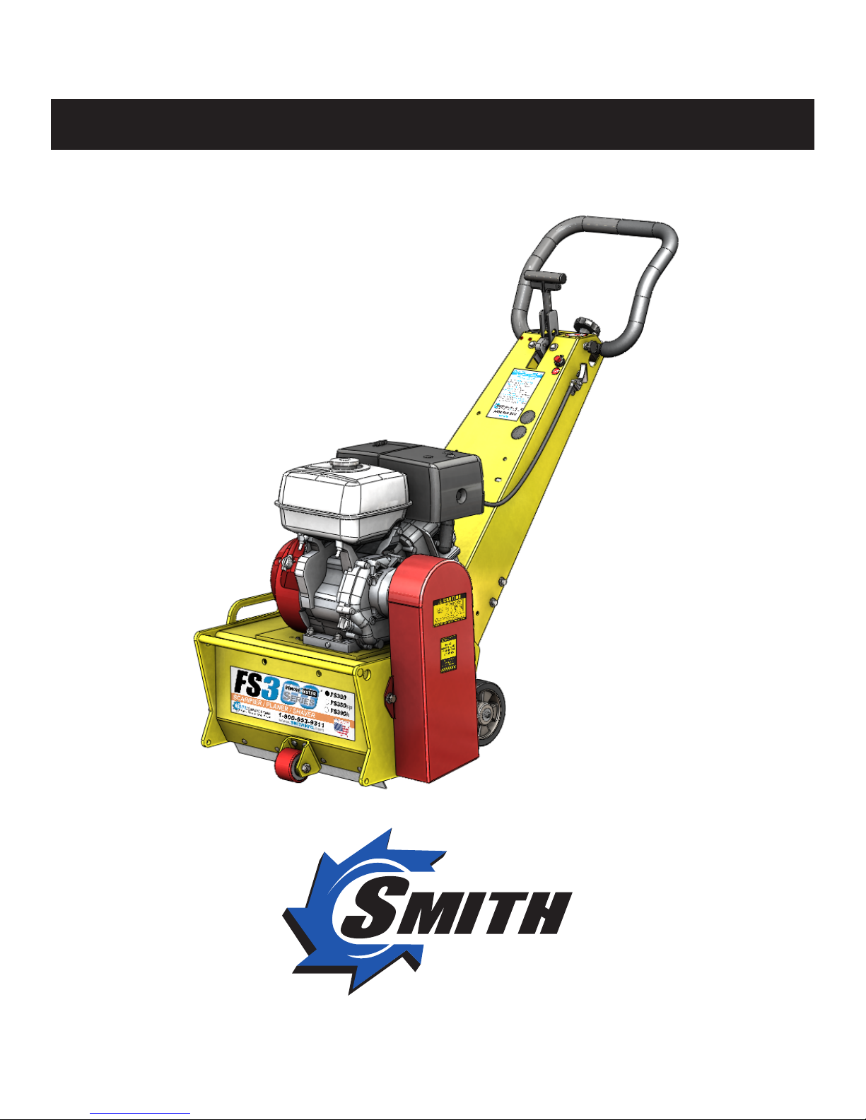
Congratulations on purchasing the
FS300™ heavy duty remover from
SMITH Mfg. Company.
Your machine will:
• Clean surfaces impacted by grease, oil,
plastics, tars, resins, tile adhesives, ice and
more
• Plane or mill asphalt and concrete surfaces
• Remove high spots in curbs and gutters
• Eliminate trip-hazards on concrete sidewalks
• Mill areas for rumble strips
• Clean out cracks and joints
• Create anti-slip patterns in walkways and barns
• Prepare surfaces for new coating applications
• Permanently remove all road and surface
coatings to include:
epoxy, urethane, thermoplastic, paint,
glue-backed tapes and more...
• Groove-inlay asphalt for striping
BEFORE START-UP,
READ THIS..
Please read all operating instructions, including
the provided motor manual and be completely
familiar with your equipment before operating.
When in doubt, please contact SMITH
Manufacturing Customer Service for operational
details. This Owner’s Manual will guide you
through the removal process, from start to nish,
and show you how to care for your machine.
Page Contents
2Index / Introduction
3Safety Guidelines
4Your FS300 Surface Preparator
5Handle Adjustment Instructions
6Machine Start-Up
7Substrate Removal
8Storage, Ordering, and Warranty Claims
9Troubleshooting
10 Maintenance Check List
11-12 General maintenance
13-14 Bearing replacement
15-17 Optional Equipment
18-19 Maintenance Log
20 Limited Equipment Warranty
21 Warranty Activation
INDEX

SMITH Manufacturing 1-954-941-9744 www.SmithMfg.com
SMITH Manufacturing 1-954-941-9744 www.SmithMfg.com
VERSION 8/2013
FS300
Gas
3
UNCRATING EQUIPMENT
When you uncrate your equipment, make certain
that the machine has not been damaged and
that all fasteners and guards are properly
tightened.
Your machine may not have been shipped
assembled with cutters and other accessories.
Assembly may be required.
REMEMBER: Only authorized, experienced and
properly trained personnel should operate this
equipment. Operating personnel should prac-
tice safety at all times and ear protective gear
(gloves, goggles, safety vests, ear plugs, steel-
toe shoes, etc.)
• Always wear protective equipment, including
ear protection and goggles.
• Never wear baggy or loose tting clothing that
can be caught on controls or moving parts.
• The surface preparator can emit ying
particles and debris during operation. Never
operate the machine near bystanders, animals
or children.
• Check uid levels and get acquainted with the
controls.
• Do not operate the machine in an explosive
atmosphere, near combustible materials, or
when gas fumes may not be properly dispersed.
• Never leave the machine unattended when
running, and you must hold onto the handle with
two hands when the cutter drum is engaged.
• Ensure that all guards are in place before the
machine is operated, since rotating and moving
parts will cause injury upon contact.
• Make sure that the machine is unplugged from
any power source before servicing.
Incorrect use of the surface planer can
result in property damage, personal injury,
or death. Be sure to read and follow all
directions and precautions as outlined in
this manual.
SAFETY GUIDELINES

SMITH Manufacturing 1-954-941-9744 www.SmithMfg.com
FS300
VERSION 8/2013
Gas
SMITH Manufacturing 1-954-941-9744 www.SmithMfg.com
YOUR FS300TM SURFACE PREPARATOR
Please take time to familiarize yourself with the FS300™’s
controls, as well as some of the features of your new machine.
Read the engine manual before preparing the engine for starting.
Adjustable Handlebar
Cutter height adjustment
Corded “engine kill” button
Removable Side Plate
4
Oil Dipstick
Engine Shut-Off
Gas Tank
Throttle
Cyclone Air Cleaner

SMITH Manufacturing 1-954-941-9744 www.SmithMfg.com
SMITH Manufacturing 1-954-941-9744 www.SmithMfg.com
VERSION 8/2013
FS300
Gas
HANDLE BAR ADJUSTMENT
The handlebars are equipped with a high-density
vibration suppression material to minimize
operator fatigue and increase comfort level when
operating equipment. To adjust the handlebars
to a new position for different height operators
please follow these steps:
• Using a wrench or socket (13mm), loosen
the bolts on both sides of the handlebars
two to three turns only.
• Adjust handlebar to desired position and
re-tighten the 4 screws
Never operate with handlebars loose.
The bolts must be fastened tightly assuring
the handle is locked into position.
Loosen to
adjust
5

SMITH Manufacturing 1-954-941-9744 www.SmithMfg.com
FS300
VERSION 8/2013
Gas
SMITH Manufacturing 1-954-941-9744 www.SmithMfg.com
MACHINE START-UP
Do not start machine while drum is in
contact with the ground. Doing so can
cause the operator to lose control of the
machine, resulting in property damage
and/or personal injury.
NOTE: Do not attempt to raise or lower the cam
lever by force. If it does not move effortlessly,
raise or lower the hand wheel until the cam lever
can be adjusted. Open the fuel cock on the
carburator and then place the throttle lever at the
“Fast Idle” position. Start the engine, open choke
slightly to prevent ooding. Move throttle control
to open or run position when engine is warmed
up. Increase throttle to maximum operating posi-
tion (approx. 2800RPM) and close choke. Before
substrate removal, test run the drum with cutters
not touching the surface. If there is excessive vi-
bration, you need to re-balance the cutter set-up,
check bearing condition, and/or make sure that
the drive shaft is secured.
Corded “Engine Kill” Button (not available
on electric motor): In the event of a malfunc-
tion or an accident (such as the machine op-
erator falling or losing footing), the SPS10 is
equipped with a corded “Engine Kill” Button.
Attach the end of the cord to the operator’s
belt or wrist, and snap the clip into place on
the stop switch by raising the top of the Engine
Kill Button and inserting the clip into the gap.
If the operator becomes distanced too far from
the machine, the cord will detach from the stop
switch, and the machine will stop running.
Attatch to
operator
*NOTE: the Engine will not start without the
Corded Engine Kill’s clip securely in place.
CAUTION: The machine will still move with
the engine off.
IF THE ENGINE DOES NOT
START
1) Check Engine for proper gas and oil levels
(refer to Engine manual)
2) Check spark plug. Make sure the socket
areas are clean and clear of debris, and that
the proper gap is set. (Replace if needed).
3) Check Brown Electrical clip hanging on the
front of the engine and ensure that the
electrical wires are making contact within the
clip.
4) Turn the On/Off switch, on the front of the
Engine, to “On”.
5) Check Corded Engine Kill Button’s
Connections:
a) Make sure the Corded Safety Stop “C”
Connector is dipped properly.
b) Try switching the connection to the opposite
post (From letter “C” to letter “M”, for example).
6) Engine may have tilted backwards. If so,
allow oil to drain after removing spark plug and
pulling starter cord several times
*Engine repair and engine warranty
issues are handled directly
by your local engine service center.
6

SMITH Manufacturing 1-954-941-9744 www.SmithMfg.com
SMITH Manufacturing 1-954-941-9744 www.SmithMfg.com
VERSION 8/2013
FS300
Gas
7
SUBSTRATE REMOVAL
Warning: Should you desire to tilt the
machine, always tilt forward. Tilting the
machine backwards at any time will ood
the spark plug with oil and may cause
damage to your engine!
Adjust the height of the cutter drum with
the Hand Wheel and Cam Lever. (Turn the
hand wheel to raise the cutter drum off of the
substrate. Lower or raise the cam lever to
engage or disengage the drum after setting
the proper cutter depth.)
Set the deoth of cut to allow the cutters to go
through only the materials to be removed.
Make certain that the drum is positioned to
where only the cutters strike the surface,
and that the drum assembly never comes
into contact with the substrate. The cutter
tips alone should strike the surface (1/8”
to 1/4” maximum depth per removal pass on
new cutters).
The drum will not withstand substrate
contact. Contacting the removal surface
too deeply will cause premature wear to
cutters, shafts, drum and other
components!
Too much downward pressure only has
negative results. Try to remove materials in
several passes rather than one, deep pass.
Several tests will show the best, most
appropriate cutter impact. Use a forward,
backward and/or circular pattern to achieve
your desired nish.
NOTE: Only use a forward motion when the
CM2150 or CM2550 carbide milling cutters
are used.
TIP: Positioning the machine over the
surface in many direrctions, as well as
dialing the hand wheel up or down can help
create desirable surface patterns.
After several hours of practice, the operator
will become comfortable and should be able
to remove materials faster with enhanced
results.
When the job is completed, or the operator
wants to cease work, stop the engine by rst
lifting the drum above the substrate using the
hand-wheel and/or the cam lever. Stop the
machine only at the engine. Then close the
fuel cock to shut off the fuel supply.
The drum assembly must be removed daily
and inspected for drum wear, hole
elongation and possible weld separation.
Replace the cutter shafts and drum bushings
every 40 hours, or prior to any drum wear. If
the drum’s center holes are elongated, oreder
another SMITH cutter drum.

SMITH Manufacturing 1-954-941-9744 www.SmithMfg.com
FS300
VERSION 8/2013
Gas
SMITH Manufacturing 1-954-941-9744 www.SmithMfg.com
STORAGE
Shut off fuel valve and remove all fuel or
add fuel stabilizer. Start engine and run until
it stalls. Remove spark plug and pour two
ounces of motor oil into cylinder and slowly
crank the engine by hand to distribute oil to
prevent rust during storage.Replace spark
plug and store machine upright in a cool, dry,
and well-ventilated area.
ORDERING
To ensure product safety and reliability,
and to maintain your warranty, always use
genuine replacement cutters and partsfrom
SMITH when making repairs to equipment.
When oredering please specify the model and
serial number of the machine. In addition, give
a part number, description, and quantity as
listed on your parts list.
If you have any questions about the operation
of your machine or would like to order
replacement parts, contact your SMITH
Manufacturing representative directly.
Contact 1-800-653-9311 (954-941-9744)
for information.
Visit our website at
www.smithmfg.com
WARRANTY CLAIMS
The manufacturer reserves the right to
change or improve the machine design with-
out assuming any obligation to update any
products previously manufactured before
this manual. It is the customer’s responibility
to complete the warranty card and mail it to
the seller within 10 days from date of pur-
chase. If a failure occurs during the warranty
period, the customer must contact the seller
to determine the appropriate action.
Any and all transportation charges are to
be borne by the purchaser.
8

SMITH Manufacturing 1-954-941-9744 www.SmithMfg.com
SMITH Manufacturing 1-954-941-9744 www.SmithMfg.com
VERSION 8/2013
FS300
Gas
TROUBLESHOOTING
PROBLEM
Possible Reason(s)/Solution(s)
CUTTERS WEARING
UNEVENLY/PREMATURELY
Drum is too low
Icorrect set-up
Material Build-up
Cutters too tightly loaded
Wrong cutters for
application
CUTTERS SHAFT BREAKAGE
UNEVENLY/PREMATURELY
Drum is too low
End plates or bushings worn
Shafts worn
Wrong cutter set-up
Over 40 hours service-life
DRUM WEARING
PREMATURELY OR CRACKING
Drum hitting ground
Shafts and bushings not replaced
within 40 hours
EXCESS VIBRATION
Bearing worn
Hex bushing worn
Drive shaft worn
Improper cutter set-up
Drum contacting ground
Wheels worn out
MACHINE JUMPS
ERRATICALLY
Drum hitting ground
RPM is too low
Surface is severely uneven
DRIVE BELT WEARING
PREMATURELY
Pulley is misaligned
Wrong belt
Drum is contacting
the surface
MACHINE WONT MOVE IN
FORWARD OR REVERSE
Check hydraulic reservoir level
Verify v-belt to hydraulic pump
is not slipping or damaged
*Engine repair and engine warranty
issues are handled directly
by your local engine service center.
For any other problems or questions,
please contact your local representative
or
SMITH Mfg today at 800-653-9311
or
(954) 941-9744.
9
Check lifting carriage is in
upright position and drive
wheels in cocntact with ground

SMITH Manufacturing 1-954-941-9744 www.SmithMfg.com
FS300
VERSION 8/2013
Gas
SMITH Manufacturing 1-954-941-9744 www.SmithMfg.com
MAINTENANCE CHECK LIST
Note: Make sure the ignition is in the OFF
position, and the spark plug is disconnected
before servicing
• Maintain proper engine oil and crankcase
levels.
Change every 25-50 hours
(see Honda manual).
• Clean spark plugs regularly, and set the
proper gap.
• Wash the air cleaner element in a non oil-
based solvent, then squeeze out residue.
Allow lter to dry before reinstalling in cleaner.
• Keep a coating of grease on the drive shaft
and threads for easy installation or removal,
and for longer hex bushing life.
• Check all fasteners and re-tighten, since the
machine will vibrate the fasteners loose if they
are not secured. Use locktight.
• Check the Drive belt for wear, and adjust
(tension), or replace as required.
After replacing belts, check for proper tension:
• Adjust Idler to tension belt. Do not over
tighten.
• Check that the pulleys are aligned properly
to ensure the belts are running true.
10
• The inside housing must be clean, and
remove any build-up from inside the cage so
cutters and drum rotate freely.
• Inspect and change drum bushings and
shafts every 40 hours, or when worn.

SMITH Manufacturing 1-954-941-9744 www.SmithMfg.com
SMITH Manufacturing 1-954-941-9744 www.SmithMfg.com
VERSION 8/2013
FS300
Gas
DRUM REPLACEMENT
Drum replacement is easy and requires a
few hand tools.
1. 17mm socket or wrench
2. Rubber mallet
Before beginning servicing on any
gasoline-powered unit,
DISCONNECT SPARK PLUG WIRE!
1. Lower the machine so the cutter drum is
resting on the ground. Do this either with
the cutter height adjustment handle or with
the lift carriage foot lever.
4. Slide out drum assembly. (use precaution
as it is HEAVY)
2)
4)
5. Once the cutter drum is removed take to a
workbench for assembly.
a) Inspect condition of cutters,
spacers, shafts, bushings and drum.
6) Before replacing the drum onto hex shaft:
a) Check that all bearings are in
good working order
b) Remove dirt and material build-up
from inside drive carriage and drum.
c) Lube all metal contacts
6) Align and slide drum back onto the hex
shaft.
7) Replace side plate (lift-up and lock into
place) over hex shaft and secure hardware.
NOTE: It is recomended that you use a
wooden board or something similar to place
under the drum before lowering the machine
to take the drum weight off the shaft which
makes it easier to align with side plate
2. Remove the four hex head cap screws
from the sideplate using the 17mm socket
or wrench.
3. Remove the sideplate (this may require
the rubber mallet to break it loose)
*TIP: SMITH recommends owning
an extra drum loaded with cutter for
rapid job-sight
11
3)
SMITH Manufacturing 1-954-941-9744 www.SmithMfg.com
FS300
VERSION 8/2013
Gas
SMITH Manufacturing 1-954-941-9744 www.SmithMfg.com
12
DRIVE BELT REPLACEMENT
Normal wear may necessitate belt
tensioning or replacement.
Time of replacement will vary according to
usage and belt load factors.
Replacement is easy and requires a few
hand tools.
1. 17mm socket or wrench
2. 19mm socket or wrench
Before beginning servicing on any
gasoline-powered unit,
DISCONNECT SPARK PLUG WIRE!
1. Make sure the removable side cover is
installed. This insures the drive ends are in
the proper position for servicing.
2. Clean the machine exterior so you can
locate all the appropriate parts.
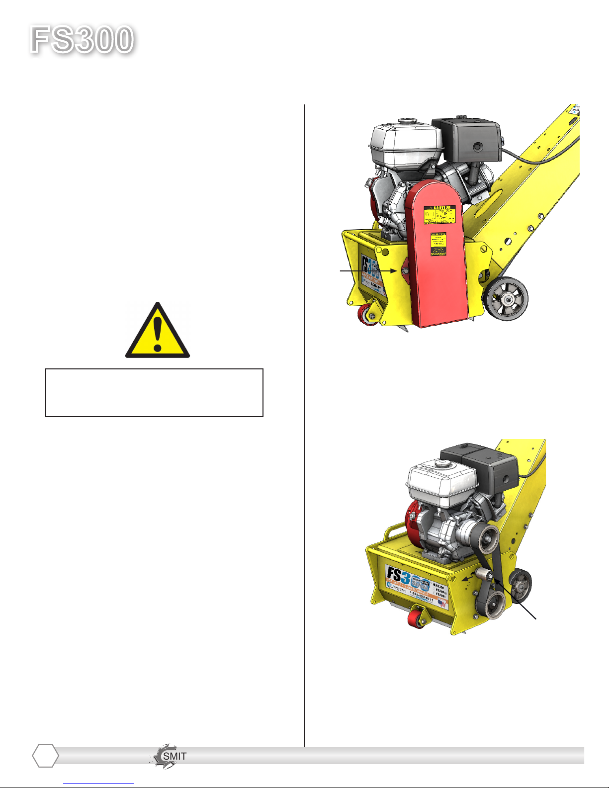
3. Using a 17mm socket or wrench, remove
the two hex nuts attaching the belt cover to
the side of the machine. Remove the cover
and set it aside.
3)
4. Loosen (do not remove) the hex screw
on the idler pulley using a 19mm socket
or wrench and slide the pulley towards the
front of the machine to release belt tension,
remove/replace the belt as needed.
4)
5. To tension the belt once again, push the
idler against the belt and tighten it down
with the 19mm socket or wrench.
DO NOT overtighten the belt as it will cause
it to wear prematurely.

SMITH Manufacturing 1-954-941-9744 www.SmithMfg.com
SMITH Manufacturing 1-954-941-9744 www.SmithMfg.com
VERSION 8/2013
FS300
Gas
BEARING REPLACEMENT
Before reading ahead go back and follow
the instructions on how to remove the drum
and drive belt from the machine. Bearing
replacement is easy and requires a few
addtional hand tools.
1. 17mm socket or wrench
2. 9/16” socket or wrench
3. Adjustable wrench up to 1.5”
4. 7/32” Hex Key
5. Circlip pliers
Before beginning servicing on any
gasoline-powered unit,
DISCONNECT SPARK PLUG WIRE!
1. With the sideplate off the machine, use a
wrench to lock the rotation of the shaft.
Using the 9/16” socket, remove the screw
that locks down the pulley to the shaft.
2. With the shaft rotation still locked, use a
7/32” hex key to remove the 2 set screws on
the drive pulley (A). Once they are removed,
insert one of them into the hole directly on
top of the keyway to back out the bushing
as shown below (B).
1)
2A)
2B)
3. With the Pulley and shaft removed, use
the 17mm socket or wrench to remove the
bearing housing assembly from the frame.
3)
3. With the Pulley removed, use the 17mm
socket or wrench to remove the bearing
housing assembly from the frame and from
the side plate .
13
SMITH Manufacturing 1-954-941-9744 www.SmithMfg.com
FS300
VERSION 8/2013
Gas
SMITH Manufacturing 1-954-941-9744 www.SmithMfg.com
BEARING REPLACEMENT
(CONTINUED)
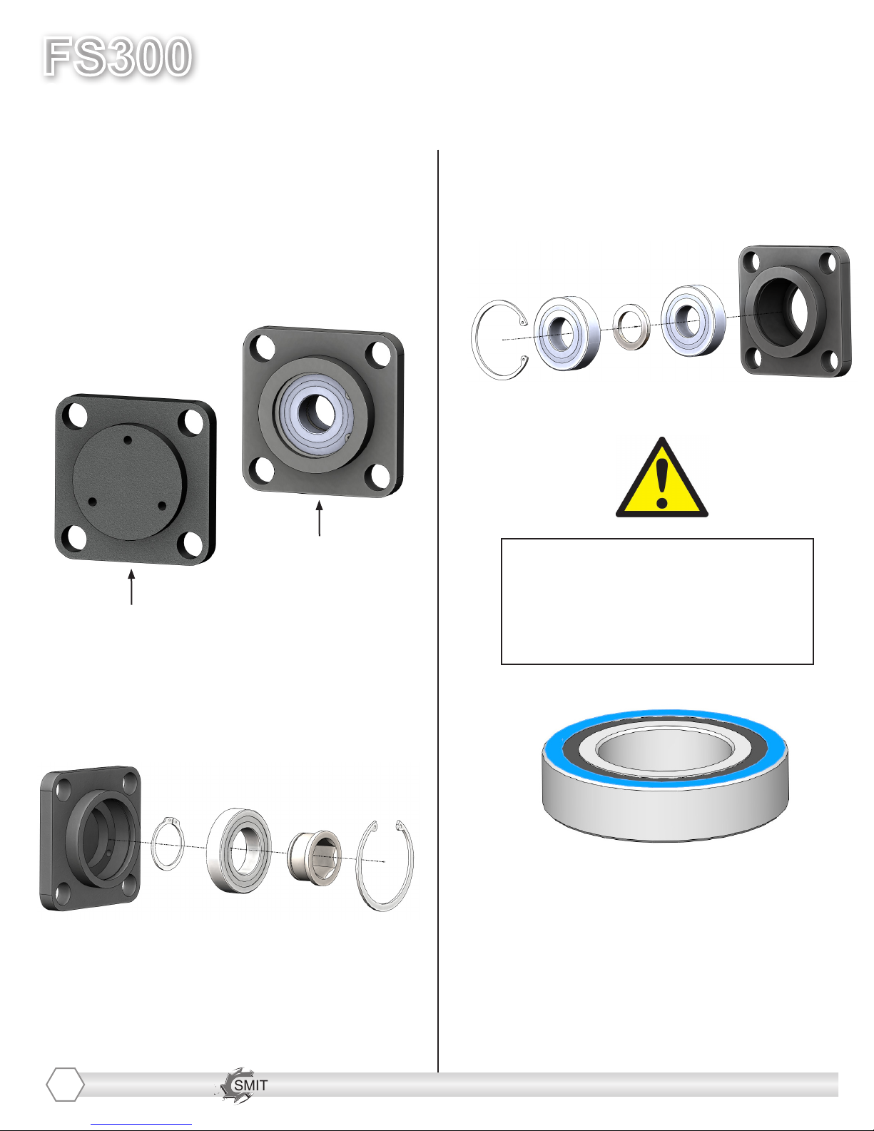
4. With the bearing housing assemblies
aside, they can now be taken apart to
replace the bearings as needed using the
circlip pliers.
6. The belt side bearing assembly shown
below.
Sideplate side
bearing housing
Belt side bearing
housing
5. The sidelpate side bearing assembly
shown below.
***WARNING***
When pressing bearings in,
use a soft wooden dowel and
only apply pressure to the
outter race of the bearings
14

SMITH Manufacturing 1-954-941-9744 www.SmithMfg.com
SMITH Manufacturing 1-954-941-9744 www.SmithMfg.com
VERSION 8/2013
FS300
Gas
OPTIONAL EQUIPMENT
• BALL MOUNTH HITCH
Allows attachment to other components
• POINTER/DIRECTIONAL
SIGHT GUIDE SYSTEM
Allows operator to make straight passes
easier
15

SMITH Manufacturing 1-954-941-9744 www.SmithMfg.com
FS300
VERSION 8/2013
Gas
SMITH Manufacturing 1-954-941-9744 www.SmithMfg.com
OPTIONAL EQUIPMENT
• SULKY DRIVER
with reverse mounted rear handle control
(optional upgrade-please select front or rear)
• TACH/HOUR METER
Maintenance meter for service and use
control
16

SMITH Manufacturing 1-954-941-9744 www.SmithMfg.com
SMITH Manufacturing 1-954-941-9744 www.SmithMfg.com
VERSION 8/2013
FS300
Gas
OPTIONAL EQUIPMENT
17
• MAXIVAC DUST COLLECTOR
Available in both gas or electric powered applications with the
standard 5 micron bags or upgrade to the 1 micron lter with
shake down bar
Fastest way to safely remove!

SMITH Manufacturing 1-954-941-9744 www.SmithMfg.com
FS300
VERSION 8/2013
Gas
SMITH Manufacturing 1-954-941-9744 www.SmithMfg.com
MAINTENANCE LOG
18

SMITH Manufacturing 1-954-941-9744 www.SmithMfg.com
SMITH Manufacturing 1-954-941-9744 www.SmithMfg.com
VERSION 8/2013
FS300
Gas
MAINTENANCE LOG
WARRANTY CLAIMS
The manufacturer reserves the right to change or improve the machine design without assuming any
obligation to update any products previously manufactured before this manual. It is the customer’s
responsibility to complete the warranty card and mail it to the seller within 10 days from the date
of purchase. If a failure occurs during the warranty period, the customer must contact the seller
to determine the appropriate action. Any and all transportation charges are to be borne by the
purchaser.
19

SMITH Manufacturing 1-954-941-9744 www.SmithMfg.com
FS300
VERSION 8/2013
Gas
SMITH Manufacturing 1-954-941-9744 www.SmithMfg.com
Limited Equipment Warranty
All statements, technical information and recommendations contained in SMITH’s literature are based on tests believed to be reliable, but the accuracy
or completeness thereof is not guaranteed and the following is made in lieu of all warranties, expressed or implied. SMITH warrants all equipment or part
referenced in this document which is manufactured by SMITH and bearing its name to be free from defects in material and workmanship on the date of
sale to the original purchaser under normal use and maintenance as herein provided. This warranty does not apply to components manufactured by others
such as, but not limited to, bearings and engines; such components that may or may not have their own warranties.
With the exception of any special, extended, or limited warranty published by SMITH, SMITH will, for a period of three months (90 days) from the
date of sale or up to ve hundred (500) hours of use by buyer, whichever shall occur rst; repair or replace any part of the equipment determined by
SMITH to be defective. This warranty applies only when the equipment or part is installed, operated and maintained in accordance with SMITH’s written
recommendations.
SMITH’s sole obligation for any breach of warranty or breach of contract for defects, deliberate or accidental omissions, shall be limited to repairing,
replacing or allowing credit for, at SMITH’s option, any part which, under normal and proper use and maintenance, proves defective in material or
workmanship within warranty period, provided, however, that notice of any such defect or omission and satisfactory proof thereof is promptly given by
buyer to SMITH, and thereafter, such defective part is returned to SMITH with transportation charges prepaid, and SMITH’s examination proves such part
to have been defective. This warranty does not obligate SMITH to bear any transportation charges or personnel time in connection with the replacement
or repair of defective parts. This warranty does not obligate SMITH to bear any expense for travel time or of personnel in connection with any service calls.
SMITH will not, in any event, be liable to the user for any consequential damages arising out of this sale for the loss of use, lost prots or revenue, interest,
lost goodwill or work stoppage. SMITH shall not be liable for any injury, loss or damage, direct or consequential, arising out of the use or the inability to use
the product or for environmental claims. It being understood that SMITH has no means of controlling the products nal use; therefore, it shall be buyer’s
responsibility to determine suitability of product for intended use and buyer assumes all risks and liabilities whatsoever, in connection therewith. In no event
shall SMITH be liable for consequential or special damages. Used products are sold on an “as is” basis, and there is no implied warranty of merchantability
or of tness for a particular purpose, unless made in writing by an ofcer at SMITH’s ofce.
This warranty does not cover, and SMITH shall not be liable for general wear and tear, or any malfunction, damage or wear caused by faulty installation,
misapplication, abrasion, corrosion, inadequate or improper maintenance, negligence, accident, tampering, or substitution of non-SMITH component parts.
Nor shall SMITH be liable for malfunction, damage or wear caused by the incompatibility of SMITH equipment with structures, accessories, equipment
or materials not supplied by SMITH, or the improper design, manufacture, installation, operation or maintenance of structures, accessories, equipment
or materials not supplied by SMITH. This warranty does not apply in respect to damages to any product or accessory or attachment thereof caused by
overloading or other misuse, neglect or accident, nor does this warranty apply to any product or accessory or attachment thereof, which has been repaired
or altered in any way which, in the sole judgment of SMITH, affects the performance, stability or general purpose for which it was manufactured. In the
manufacture of buyer’s equipment, parts may be omitted or equivalent functioning equipment and components may be substituted for the original specied
equipment upon the sole judgment and discretion of SMITH.
This warranty is conditioned upon the prepaid return of the equipment claimed to be defective to an authorized SMITH Reseller for verication of the
claimed defect. If the claimed defect is veried, SMITH will repair or replace free of charge any defective parts and return of merchandise back to the
customer freight collect. If inspection of the equipment does not disclose any defect in material or workmanship, repairs will be made at a reasonable
charge, which charges may include the costs of parts, labor and transportation.
THIS WARRANTY IS EXCLUSIVE AND IS IN LIEU OF ANY OTHER WARRANTIES, EXPRESS OR IMPLIED, INCLUDING BUT NOT LIMITED TO
WARRANTY OF MERCHANTABILITY OR WARRANTY OF FITNESS FOR A PARTICULAR PURPOSE.
SMITH’s sole obligation and buyer’s sole remedy for any breach of warranty shall be as set forth above. The buyer agrees that no other remedy (including,
but not limited to, incidental or consequential damages for lost prots, lost sales, injury to person or property, or any other incidental or consequential loss)
shall be available. Any action for breach of warranty must be brought within two (2) years of the date of sale.
SMITH MAKES NO WARRANTY, AND DISCLAIMS ALL IMPLIED WARRANTIES OF MERCHANTABILITY AND FITNESS FOR A PARTICULAR
PURPOSE, IN CONNECTION WITH ACCESSORIES, EQUIPMENT, MATERIALS OR COMPONENTS SOLD BUT NOT MANUFACTURED BY SMITH.
These items sold, but not manufactured by SMITH (such as electric motors, switches, hose, etc.), are subject to the warranty, if any, of their manufacturer.
SMITH will provide purchaser with reasonable assistance in making any claim for breach of these warranties. In no event will SMITH be liable for indirect,
incidental, special or consequential damages resulting from SMITH supplying equipment hereunder, or the furnishing, performance, or use of any products
or other goods sold hereto, whether due to a breach of contract, breach of warranty, the negligence of SMITH, or otherwise.
ADDITIONAL WARRANTY COVERAGE - SMITH does provide extended warranty and wear warranty for products.
Corrections - typographical or clerical errors contained herein are subject to correction by SMITH.
Assignment - buyer shall not assign or transfer this warranty without SMITH’s written consent.
Entire agreement and applicable law - the rights and obligations of SMITH and buyer shall be governed by the laws of the state of Florida, U.S.A. In force
on date hereof. The provisions hereof are intended by buyer and SMITH as a nal expression of their agreement, and are intended also, as a complete
and exclusive statement of all terms apply cable to buyer’s order. No waiver, modication, or addition to any of the terms hereof shall be binding on SMITH,
unless made in writing by an ofcer at SMITH’s ofce as stated herein. In the event of conict between buyer’s purchase order and the terms hereof, the
latter shall control. If any provisions herein are to any extent invalid or unenforceable, the remainder of the warranty shall not be effected thereby and shall
be valid and enforceable to the fullest extent permitted by law.
Legal action - buyer shall be responsible for all costs of collection of outstanding indebtedness, including but not limited to attorney’s fees and court costs
to seller. Buyer shall reimburse seller for any and all litigation expenses seller incurs as a result of an unsuccessful buyer claim. The jurisdiction and venue
of the court for any litigation, state or federal, brought by the buyer and/or seller shall be located in venue determined by seller.
Fair labor standards - seller’s products are produced in the United States and in conformity with all applicable provisions of the fair labor standards act of
1938 as amended and any regulations and orders of the United States Department of Labor issued thereunder.
All written and visual data contained in this document reects the most current product information available at the time of this publication. SMITH reserves
the right to make changes at any time without notice.
TO ORDER, contact your SMITH distributor or call 1-800-653-9311 to identify the nearest distributor.
SMITH Manufacturing Co, Inc.
1610 South Dixie Highway
Pompano Beach, FL 33060
www.smithmfg.com
20
This manual suits for next models
1
Table of contents
Other Smith Floor Machine manuals

Popular Floor Machine manuals by other brands

KENT
KENT Razor Blade 26D parts list

MK Diamond Products
MK Diamond Products MK-SDG-7 OWNERS MANUAL, PARTS LIST & EXPLODED VIEW

NSS
NSS STALLION 818 SC Operation manual

Tennant
Tennant T3 Operator's manual

Advance acoustic
Advance acoustic SC400 Instructions for use

Kärcher
Kärcher BD 50/70 R Bp Classic manual


MK Diamond Products
MK Diamond Products MK-VTS/50 Owner's manual operating instruction & parts list

SCANMASKIN
SCANMASKIN Scan Combiflex 330 manual

WOLFF
WOLFF TURBO-STRIPPER Translation of the original instruction
 10070100 operating instructions")
Windsor
Windsor D250(115V) 10070100 operating instructions

ADIATEK
ADIATEK Opal 66 Use and maintenance

Minuteman
Minuteman C-BOX 100 instruction manual