Smith HPW-60A User manual
Heat Pump!
HPW-60A!
HPW-80A"
User Guide"

About AOS Bath"
Congratulations on your purchase of an A. O. Smith water heater. "
"
AOS Bath is a water heater specialist that focuses on making leading water heater technologies
available in Singapore. We repesent A. O. Smith, the largest and most technologically advanced
water heater manufacturer in the world. "
"
Water heaters are one of the highest energy consumers in a household. Using green technologies,
you can save up to 80%of energy. At AOS Bath, we believe in empowering home owners with
knowledge so you can make choices suitable for your household. No longer should you have to
settle with obselete technology. "
"
A. O. Smith has delivered innovative residential and commercial solutions for over 140 years. "
2
Heat pump
heater"
What’s in the box? "
User guide"Wall mounting
accessory"Safety valve"Drain pipe"

Contents
!
Specifications ...................................................................6"
Key features ......................................................................7"
Blue Diamond tank"
Blue Diamond elements"
Touch control panel"
Hot water display"
Instant heating"
MAX function"
Intelligent dormancy"
Programmable timer"
3 year full warranty"
Thermal cut out"
High efficiency insulation"
Pressure relief valve (safety valve)"
Anode protection"
"
Installation .........................................................................9"
Mounting"
Mounting procedures and precautions"
Mounting guidelines"
Plumbing connection"
Water inlet and outlet connection"
Power connection"
Water filling"
Installing the remote control"
Remote control battery"
"
Directions for use .............................................................. 14"
"
Maintenance instructions ..................................................19"
Maintenance "
Cleaning the filter"
"
Troubleshooting ..................................................................21"
Wiring diagram"
3

User guide"
Please read the instructions carefully before the installation or operation of this heat pump Water
Heater. This manual is meant for your future reference."
"
• Only professional installers recommended by AOS Bath will install the AOS heat pump for you.
For improper installation of the heater by unauthorized personnel, AOS Bath will not be
responsible. "
• If the user installs the heat pump system manufactured by themselves or does it by using the
self-prepared installation materials, AOS Bath will not be liable for any adverse effects on the
normal operation and service performance of the heater, including but not limited to pipeline
leakage, fall or improper installation thereof, and harmful effects on or damage to the body of the
heat pump system as well as all losses incurred thereby. "
• After installation and operation of the heat pump system, users should inspect the heat pump
system regularly and make necessary maintenance checks according to the service conditions. If
any abnormality occurs, stop the operation of the heater immediately, and contact the local
authorized dealer for repair to ensure the normal, safe, and reliable operation of the system. "
• The anode rod is a consumable part and should be examined and replaced at fixed periods.
Consumers should register and replace the anode rod by contacting the local authorized dealer.
In this way, the service life of the heat pump system will be extended effectively."
• Prior to any maintenance or repair of the heat pump system, please cut off the power supply.
Installers who are not recommended by AOS Bath should not adjust and repair the heater. "
• In case the heat pump water heater is subject to dry heating, the generated steam or burning
water may lead to serious scalds. Therefore, it is necessary to fill the heat pump system with
water. If dry heating occurs, cut off the power and water supply at once, stop the operation,
contact the local authorized dealer and carry out inspection or repair by AOS Bath’s
acknowledged professional installers. "
• Any component soaked into water in the tank can only be used after being inspected or repaired
by AOS Bath’s acknowledged professional installers. "
• Any damaged cords must be replaced by the repair department and professional staff
acknowledged by AOS Bath. Primary components of the heat pump system are protected by an
insulation layer and thermal protective coating. "
• The heat pump system is equipped with a relief valve. To ensure safe operation of the system, the
mounting position of the valve shall not be changed without permission, and the blockage of
valve outlet is strictly prohibited. A discharge pipe shall be provided for the relief valve, mounted
downwards continuously. The discharge pipe shall be directly connected to the floor drain. "
4

Water discharged from the heat pump (including high temperature heating water) shall not be used
for drinking. "
"
The heat pump system shall be installed in a dry place. Never insert or disconnect from the power
source with a wet hand. "
"
The heater shall be permanently connected to the electricity supply using a double pole linked
switch that has a contact separation of at least 3mm between poles incorporated in the circuit and
out of reach from the person using the shower. All wiring must conform to local requirements. "
"
Do not use the damaged electric wire, aged, loose and incorrectly fixed power sources. This will
prevent the risk of electric shocks, short circuits, fires, etc. Ensure the power source is connected
well. "
"
If the supply cord is damaged, it must be replaced by AOS Bath in order to avoid a hazard. "
"
This appliance is not intended for use by persons (including children) with reduced physical, sensory
or mental capabilities, or lack of experience and knowledge. They should be given supervision or
instructions concerning use of the appliance by a person responsible for their safety. "
"
Children should be supervised to ensure that they do not play with the appliance. "
"
A. O. SMITH Water Heating Company Ltd and AOS Bath Pte Ltd reserve all rights to interpret the
abovementioned provisions. "
Caution "
Failure to follow these instructions may lead to risk of fire and could cause property damage and or
personal injury or death. In order to avoid a hazard due to inadvertent resetting of the thermal
cutout, this appliance must not be supplied through an external switching device such as a timer, or
connected to a circuit that is regularly switched on and off by the utility. "
Warning"
Power-on and operation will be permitted only after reliable grounding is provided for the power
socket. The heat pump system is strictly forbidden for use in circumstances where no safe
grounding or well-drained floor drain is provided. In the installation area, it should be ensured that
the water leakage of the heat pump system or joints may not cause damage to the articles in
adjacent regions or lower portions of the building. "
5

Specifications"HPW-60A"HPW-80A"
Rated volume (L)"60"80"
Power, heat pump mode (kW)"0.21"0.21"
Power, electric mode (kW)"3.2"3.2"
Voltage/frequency (V/Hz)"230~/50"230~/50"
Temperature range (°C)"35 – 75 ± 5"35 – 75 ± 5"
Max/min ambent temperature (°C) "18 – 38 ± 5"18 – 38 ± 5"
Noise level (dB)" ≤40" ≤40"
Rated water pressure (MPa) "0.8"0.8"
Inlet/outlet connection (inches) " ½ " ½ "
Waterproof grade"IPX4"IPX4"
Net weight (kg) "42"45"
Dimensions"HPW-60A"HPW-80A"
Length (mm)"837"992"
Width (mm)"465"465"
Height (mm)"473"473"
Specifications"
6

Blue Diamond elements are more scale-resistant and have higher heating
efficiencies than conventional steel elements. "
Key features"
Blue Diamond elements Patent ZL200510037670.1"
Blue Diamond tanks provide higher superior corrosion resistance and durability
than steel or stainless steel tanks. "
Blue Diamond tank Patent US6303183"
Full control of your water heater. Get real time hot water visuals, adjust your
temperature to save 40% of energy or $200/year."
Touch screen control panel"
Instead of waiting 20 minutes for hot water as with conventional heaters, get hot
water in 2 minutes at the touch of a button. "
Instant heating Patent ZL200820185859.4"
MAX Heating gives you about twice as much hot water as a conventional electric
heater without consuming more energy."
MAX heating Patent ZL200820185859.4"
Heater runs only when programmed and goes into energy saving mode when
not in use. "
Built-in timer"
The smallest heat pump in the world, saves over 80% of energy or $600/year
by absorbing free ambient heat. "
Micro heat pump Patent ZL201020224011.5"
7

Memory chip records up to 21 days of your family’s usage habits and send data
to the heater for more efficient heating at the lowest cost. "
Automatic Energy Saver Patent ZL00112584.2"
AOS Bath provides the longest on-site water heater warranty in Singapore for
A. O. Smith. Other brands provide full warranties for only 1 year. "
AOS Bath 3 year full warranty"
3
The thermal cut out cuts off the power supply to the water heater in case the thermostat fails to work
and the water temperature exceeds 90°C. If this occurs, please contact AOS Bath immediately. "
Thermal cut out"
Other features"
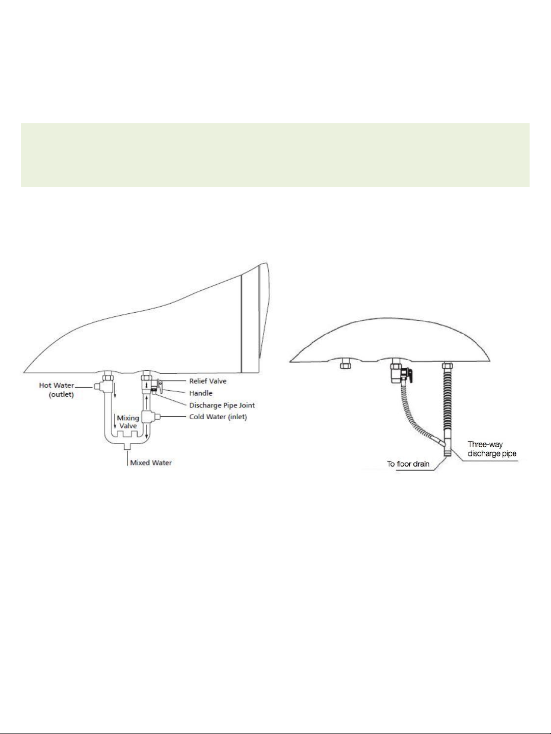
The safety relief valve is a safety device installed at the tank inlet. The valve will relieve pressure in the
tank when it exceeds 0.8MPa in the form of intermittent water droplets. The discharge port of the
relief valve and the condensation pipe should be connected to the floor drain through a three-way
discharge pipe. They should be mounted downwards continuously in a frostless environment and the
pipe must be connected to the floor drain directly. Under no circumstances should the three-pass
discharge pipes be blocked, twisted, or exposed to the atmosphere. (For installation of the relief valve
refer to Fig. 6 and 7) "
Safety valve"
The tank is fitted with a sacrificial anode rod which prolongs the life of the water heater. "
Anode"
The tank is insulated with thick, high density expansion foam to prevent heat loss. "
High density insulation"
Caution"
Hot water over 50°C will cause severe burns. "
8

Installation"
Caution"
• Please wait for 30 minutes before using the heater for the first time."
• The heater should only be connected to a power source after a full installation which ensures
secure mounting, piping, wiring and filling of the tank with water. "
• To prevent injuries from lifting heavy equipment, the heat pump should be installed by at least 2
persons."
• The heat pump must be lifted in an upright position. Do not tilt over a 45° angle. Disassembly and
assembly by end users are prohibited. "
Mounting"
This heat pump system should be installed at a location that is close to a power source, floor drain
and water utilization point. This heat pump system should not be installed in places filled with fumes,
strong electromagnetic waves, high fluctuations of power voltage, acid or alkaline vapor. "
"
The air inlet of the heat pump system should be as far away from high temperature sources as
possible and should not be covered, as the outlet of the relief valve might discharge water during the
operation of the system. A floor drain must be provided near the heater. "
"
Vertical installation of the water heater is strictly prohibited. "
Mounting procedures and precautions "
The installing surface must be capable of supporting at least four times the weight of the heat pump
system when filled with water. If the heat pump system is not installed on the bearing wall or is
mounted on hollow brick wall, corresponding protective measures must be provided. "
"
Prior to confirming the positions of bolt holes, ensure that at least 300mm space on the right side of
the heat pump system is left unoccupied. This is to allow for easy maintenance. "
"
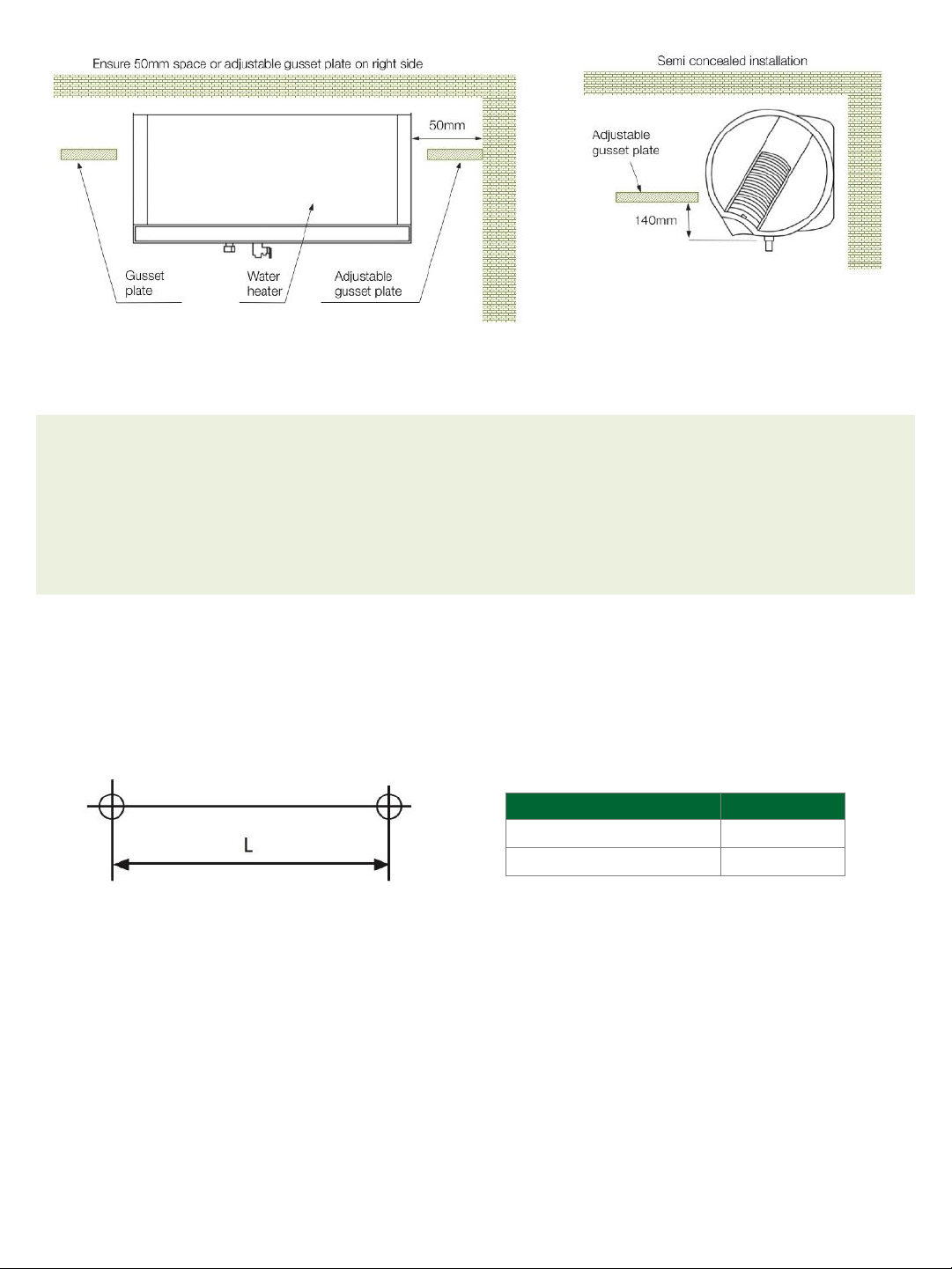
If the heat pump system is embedded into a gusset plate, the plate on the right side should be
adjustable to allow for easy repair and maintenance. The distance between the gusset plate and front
of the heat pump system should be larger than 50mm, to ensure good ventilation during running of
the system under energy-saving mode. The heat pump may also be semi-concealed. Refer to Fig. 2
for details. "
"
The heater should not be located outdoors or in an area subject to freezing environments. If freezing
occurs, the container and water pipe will break, causing scalds or leakage. "
"
9
Caution"
• This heat pump must be installed with the fixing accessories provided. The heat pump must be
mounted only when the accessories are fixed firmly or the tank may fall and serious injuries
sustained. "
• The maximum wattage of the heat pump is 3200W, hence a single phase, dedicated power supply
is proposed. The core area of the electric supply wire should not be less than 2.5mm². "
Mounting guidelines"
Drill two holes at least 105mm in depth using an electric impact drill with a Ø 10mm bit. The holes
must be level. Space between the two holes should be as shown below."
Model"L (mm)"
HPW-60A"260"
HPW-80A"380"
A nylon expansion tube must pass through the hole of the mounting bracket first, and then inserted
into the drilled holes. It is necessary to use a special inner hexagon spanner to fasten the bolts into the
nylon expansion tubes, no other tools are permitted. During fastening of the screws, ensure that the
counter sunk head of the screw is not excessively tightened, which may damage the nylon expansion
tubes. Fix the hangers on the wall by using the inner hexagon spanner and expansion screws"
"
Insert the square holes on the upper of supporting rack at the back of the water heater into the hanger
of the hanging plate, then move the water heater down to ensure the square holes against the root of
the hanger. "
10
Fig. 1"Fig. 2"

Correct installation"Incorrect installation"
Caution"
The mounting accessories provided can only be used for solid walls as shown in the drawing above.
Improper installation may cause the water heater to dislodge. "
If the walls do not meet the minimum
standards for bearing the water heater load,
increase the mounting reinforcement
accordingly. "
Ensure the power cord is installed above the
inlet and outlet. Installation below this point
may cause water to flow down the cord to the
power source, leading to accidents. "
Plumbing connection"
Do not alter the installation position or block the relief valve. Connect the safety valve provided with this
unit to the inlet of the water heater (inlet pipe has a blue cap). The arrow points to the direction of
water flow (to the heater). The safety valve must be connected to the discharge pipe, mounted
downwards to a floor drain in a frostless environment. As water may drip from the discharge pipe
during operation of the heater, a floor drain should be provided nearby. The pipes should not be
blocked."
11
Fig. 3"
Fig. 4"Fig. 5"
Caution"
Apply proper sealant to the pipe joints to prevent leakage. Do not over-tighten the safety valve to
avoid damage."
Water inlet and outlet connection"Three-way discharge pipe connection"
Refer below for the connection of the three-
pass discharge tube. The port of the relief
valve and condensation pipe are connected
to the floor drain by the three-way discharge
pipe. "
Power connection"
This water heater must be connected by fixed wiring to the supply mains. Ensure that the fixed wiring
for the water heater is incorporated with contact separation of at least 3mm in all poles for
disconnection. The insulation of the fixed wiring must be protected by an insulating sleeving with a
temperature rating of at least 80°C."
"
Ensure the water heater is reliably grounded. The earth wire must be longer than the current carrying
conductors. The maximum power of this water heater is 3300W, hence a single dedicated power
supply circuit is proposed. The core area of the electric supply wire should not be less than 2.5 mm². "
The hot water pipe is connected to the water outlet (outlet pipe has a red cap). If the water pressure of
the inlet pipe approaches or exceeds the relief limit (0.85 MPa) of the safety valve, the valve will relieve
pressure automatically. Refer to the following diagram for the pipe connection. Nylon hoses should be
used for the connection between the tapping pipe and the heater."
12
Fig. 6"Fig. 7"

Water Filling"
After all the pipes are connected, open the discharge valve of the water heater and then the feed
valve. Fill the water heater with water and exhaust the air till a uniform water stream flows out of the
hot water outlet. This indicates that the water heater has been filled up. Close the hot water discharge
valve and check all connections for any leakage. If leakage occurs, empty the water tank, repair the
leaked connection and then refill the heater with water. Do not close the feeding valve during the filling
of water."
Installing the remote control"
For convenience of operation, the control holder may be installed on a
wall near the water heater. "
"
The remote controller must be installed at a dry area. Drill two holes on
the wall using an electric impact drill with 6mm bits. The holes must be
horizontal with 28mm of space between them. Fix the bracket on the
wall with expansion tubes and screws. "
Remote control battery"
The battery compartment is located at the back of the remote controller. Rotate the catch counter
clockwise with a coin to remove the battery cover. Load the battery into the controller, note that the ‘+’
end of the battery should face upwards. Replace the cover and rotate the catch clockwise to fasten it. "
13
Fig. 8"
Fig. 9"
Directions for use"
Caution"
Before using the water heater, ensure it is filled with water and that the power plug has been
connected properly. "
Initial power up"
When the heater is connected to the power source for the first time, the electronic controller will detect
the system. All screen indicators will glow momentarily. "
"
If the heat pump system is disconnected from the power source at this point, all settings revert to
factory settings. Programmed settings will only be retained if heater remains switched on for over 4
hours. The system can keep clock settings for 72 hours without power. "
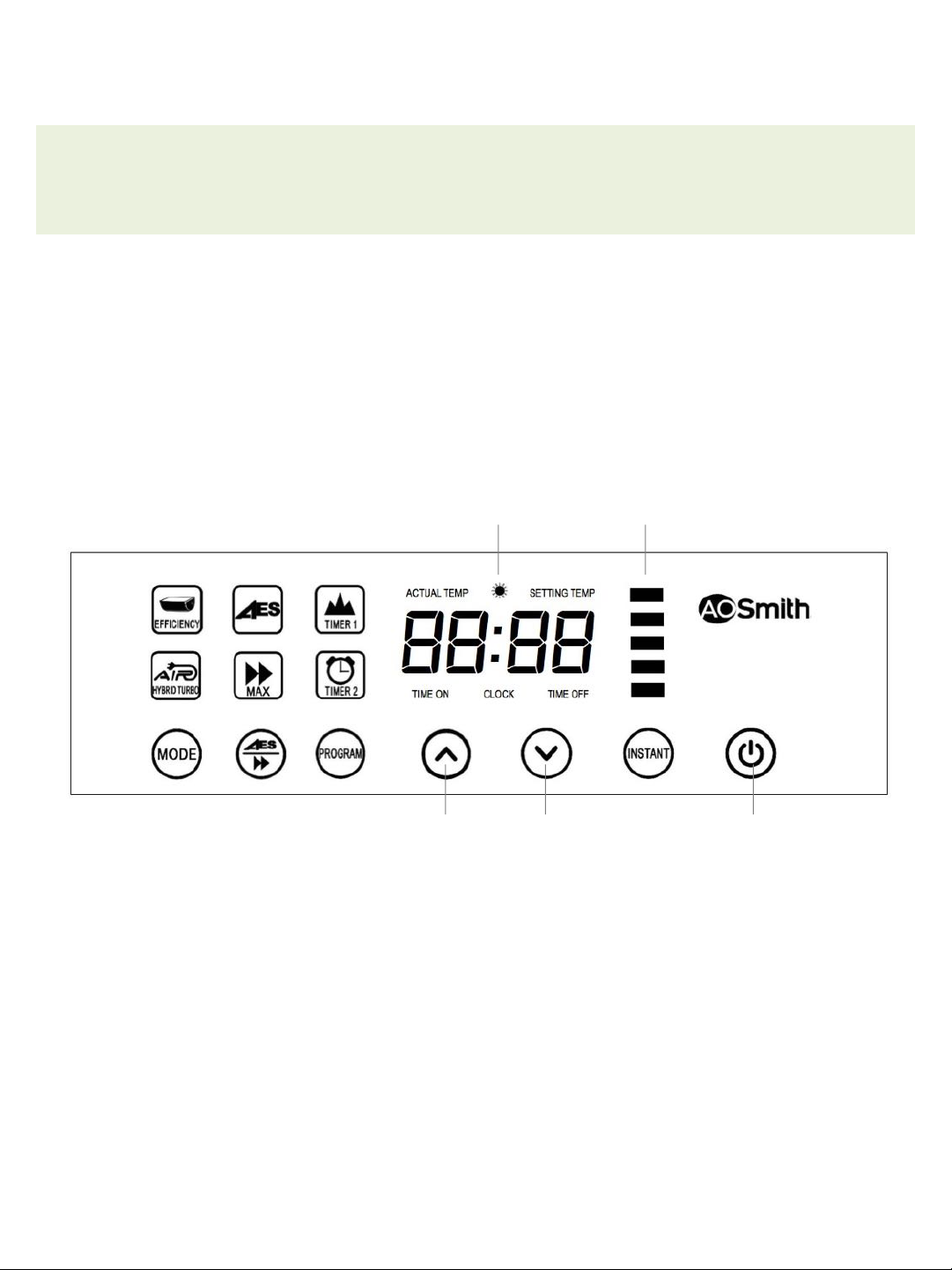
Heating indicator"Hot water indicator"
2. Power on/off"
Press the power button to turn the water heater on. The actual temperature and setting/preset
temperatures are displayed and if the actual water temperature in the tank is lower than the preset
temperature, heating begins and the heating indicator is lit. "
"
By default, the water heater is set to ‘Efficiency’ mode, Time: 12:00 and Temperature: 70°C."
Power"Decrease"Increase"
14
Fig. 10"

4. Setting the temperature"
The water heater can simultaneously display the actual temperature and preset temperature. The
actual temperature is the actual temperature of the water heater and the preset temperature is the
temperature the user would like the water to be heated to. "
"
Press the “!” the “"” buttons to adjust the preset temperature. Holding down the adjustment buttons
will cause the temperature to increase or decrease continually. The preset temperature can be set
between 35°C to 75°C."
3. Setting the clock"
Ensure the indicator lights for ‘Timer 1’ and ‘Timer 2’ are off. Hold down the ‘Program’ button for 3
seconds till the time on the screen flashes. Press the “!” the “"” buttons to set the hour, then press
the ‘Program’ button again to confirm the hour. At this point, use the “!” and“"” buttons to set the
minute. Holding down the adjustment buttons will cause the digits to increase or decrease continually.
Press the ‘Program’ button to confirm the minute. At any point after 10 seconds of inactivity, the
system will exit setting mode and the time at that point will be saved. "
15
Fig. 11"
Fig. 12"
Fig. 13"
5. Setting the timers"
Users can determine a time range for their showers so the heater can automatically ensure water is
heated during this period of time. At other times, the water heater will go into energy saving mode,
storing water at a lower temperature to optimize heat retention and thus, saving energy. "
"
Before setting the timer, ensure the clock is adjusted to the right time. Note that the timer start time is
set first, followed by the end time. If users choose not to activate the timer function, press the
‘Program’ button repeatedly till the ‘Timer 1’ and ‘Timer 2’ indicator lights are off. "
"
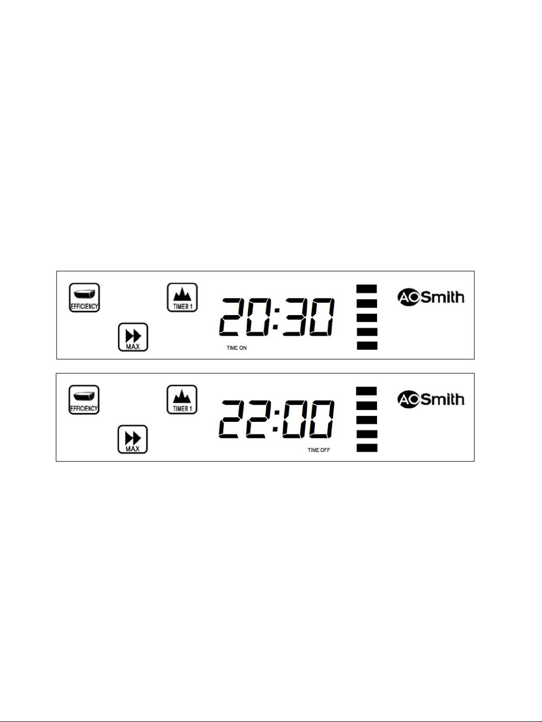
To program timer 1, press ‘Program’ button till only the ‘Timer 1’ indicator is lit, then press and hold
down the ‘Program’ button for 3 seconds till the time on the screen flashes. The indicator lights for
‘Timer 1’ and ‘Time On’ should be lit as you are now setting the start time for Timer 1. Press the “!”
the “"” buttons to adjust the start time. The “!” and “"” buttons are programmed to make 30min
increments or decrements. Press the ‘Program’ button again to finalize the start time and to start
setting the end time. The end time is set in the same manner as the start time. While setting this
timing, the indicator lights for ‘Timer 1’ and ‘Time Off’ should be lit. For example, if the timer is set
from 20:30 – 22:00, the setting panels should look like these: "
The directions for setting the second timer are the same as setting the first timer. The difference is that
while setting the second timer, ensure that the indicator light showing ‘Timer 2’ is lit before you press
and hold the ‘Program’ button to enter the setting mode. "
"
Timer 1 adjustment period: 21:00 ~ 08:00"
Timer 2 adjustment period: 12:00 ~ 21:00"
"
To turn on both timers at the same time, press the ‘Program’ button until both indication lights for
‘Timer 1’ and ‘Timer 2’ are on. The ‘AES’ program and timer will not run simultaneously. "
"
To view the timer settings, press the ‘Program’ button repeatedly to select either Timer 1 or Timer 2.
Press and hold down the ‘Program’ button for 3 seconds. The time that appears is the start time.
Press the ‘Program’ button again to show the end time. Press the ‘Program’ button again to exit the
menu. "
16
Fig. 14"
Fig. 15"

8. Instant heat function"
In situations where there is insufficient hot water in the tank, users may press the ‘Instant’ button to
generate hot water quickly. This mode activates the heating elements and the heating indicator will
flash 3 times upon activation. If the heat pump is running on ‘efficiency’ mode, it will switch to ‘hybrid
turbo’ mode when running on instant mode."
"
When the desired temperature is reached, the heating light will go off and the water heater will resume
normal operation. Otherwise, users may cancel this heating function by pressing ‘Instant’ again. The
heating indicator will flash once and go off to indicate the operation is cancelled. "
6. Heating modes"
There are two heating modes in the system. Upon making a mode selection, the system will take 3
minutes to reprogram to your selection. "
"
Efficiency mode: energy efficient heat pump heating"
Hybrid turbo mode: heat pump and speed (element) heating"
7. MAX and AES"
Toggle the AES/►► button to activate either the MAX/►► mode, AES mode, or both. AES mode will not
run simultaneously with timers and will take precedence over them. "
"
MAX is an A. O. Smith technology that allows users to get consistent hot water for long periods of
time. You can turn it on to cater for an unexpected surge in demand for hot water. "
"
AES is a memory chip that records up to 21 days of your family’s usage habits. It preheats water
according to your family’s needs and sends the heater into energy saving mode at required intervals,
saving energy by minimizing thermal loss. "
9. Hot water display"
The heater can display the amount of hot water available. The five light blocks on the left of the panel
are an indication of the quantity of hot water in the tank. "
"
Red – hot"
Orange – warm"
Green - cool"
10. System reset"
Press and hold the ‘program’ and ‘instant’ buttons for 8 seconds to revert to factory state. When the
system is reset, all screen indicators will glow for 2 seconds and the system will go offline. "
17

Electrical safety"
In the event of any circuitry issues, the system will cut off power and prompt for a reset. The colour of
the power indicator will also go from green to orange. In the event of this happening, reset the system
to restore if. If this fails, contact your local authorized dealer. "
Pressure relief valve inspection"
The pressure relief valve is a safety device installed to protect the tank against excessive pressure build
up. The valve relieves pressure when it exceeds 0.8MPa in the form of intermittent water droplets. "
!
Users should check the valve regularly by lifting the handle on the valve to discharge any calcium
carbonate deposits. If water does not discharge from your valve, please contact your local authorized
dealer. "
Remote controller"
The functions on the remote controller correspond with the buttons
on the touch screen panel of the system. The recommended
distance for usage of the remote is 4 meters. Install the batteries
before use and change the batteries every 18 months. "
18
Fig. 16"

Maintenance instructions"
Declaration"
Before using the water heater, ensure it is filled with water and that the power plug has been
connected properly. "
Warning"
Electric shock: before repairing the water heater, be sure to disconnect the water heater from the
power source."
Declaration"
Prior to repair works, please refer to the troubleshooting chart."
Maintenance"
If the water heater needs to be serviced, close the water inlet valve, then open the drain valve. Rotate
the handle of the relief valve, release the nut connected to the water outlet joint of the inner tank and
drain the water from the discharge pipe."
"
It is recommended that the tank be flushed to remove sediments which may have built up during
operation. Specific operating procedures are as follows:!
"
1. Disconnect the power."
2. Screw off the relief valve and remove the internal water inlet pipe of the water heater."
3. Connect the water outlet pipe connection of the water heater to the tap water pipeline and fill
water from this end. The water inlet pipe connection is connected to floor drain by pipes.
Discharge water from this end."
4. Open the water inlet valve to get the maximum tap water flow and flush the tank till the drained
water from the tank becomes clean."
5. Connect the water inlet and outlet pipes again and put the water heater to use after a leakage test."
Caution"
The water in the tank might be very hot and may scald. "
19
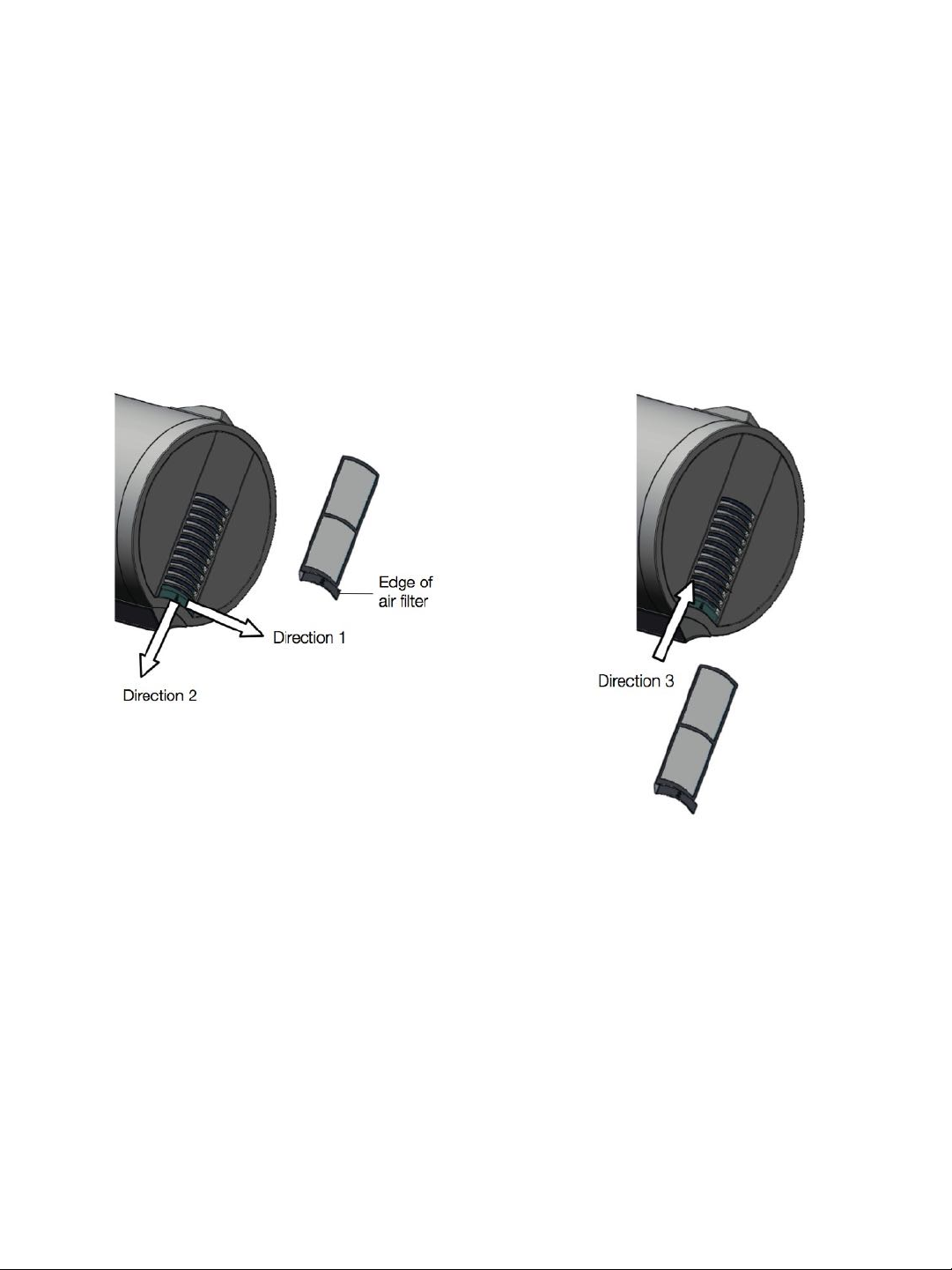
Cleaning the filter"
It is recommended that the system filter be cleaned every 6 months to ensure operational efficiency. "
"
It is recommended that the tank be flushed to remove sediments which may have built up during
operation. Specific operating procedures are as follows:!
"
1. On the right side of the system, remove the filter by pulling the edge of the filter in direction 1,
followed by downwards, direction 2. "
2. Wash and dry the air filter"
3. Reassemble the filter by slotting it upwards, direction 3. "
20
Fig. 17"Fig. 18"
This manual suits for next models
1
Table of contents
Other Smith Heat Pump manuals


Popular Heat Pump manuals by other brands

Sensa-Heat
Sensa-Heat PI Series user manual

Zehnder Rittling
Zehnder Rittling HP Series Installation, operation and maintenance

Daikin
Daikin ERQ125A7W1B installation manual

Midea
Midea MAW12HV1CWT user manual

Technibel
Technibel AF UIH Series installation instructions

evoheat
evoheat Evo315-C Installation and operation manual


 manual")


