Smiths TRAK 9100 User manual

-~
ARTISAN
®
~I
TECHNOLOGY
GROUP
Your definitive source
for
quality
pre-owned
equipment.
Artisan Technology
Group
Full-service,
independent
repair
center
with
experienced
engineers
and
technicians
on staff.
We
buy
your
excess,
underutilized,
and
idle
equipment
along
with
credit
for
buybacks
and
trade-ins
.
Custom
engineering
so
your
equipment
works
exactly as
you
specify.
•
Critical
and
expedited
services
•
Leasing
/
Rentals/
Demos
• In
stock/
Ready-to-ship
•
!TAR-certified
secure
asset
solutions
Expert
team
ITrust
guarantee
I
100%
satisfaction
All
tr
ademarks,
br
a
nd
names, a
nd
br
a
nd
s a
pp
earing here
in
are
th
e property of
th
e
ir
r
es
pecti
ve
ow
ner
s.
Find the Trak Systems 9106 at our website: Click HERE

TRAK MODEL 9100 MODULAR FREQUENCY/TIME SYSTEM
TM4400013 Rev D
TECHNICAL MANUAL
(TM4400013)
MODEL 9100
Modular Frequency/Time System
Revision D
October 2006
TRAK Microwave Corporation
4726 Eisenhower Boulevard
Tampa, Florida 33634 USA
Telephone (813) 901-7200 Fax (813) 901-7491
www.trak.com

TRAK MODEL 9100 MODULAR FREQUENCY/TIME SYSTEM
TM4400013 Rev, D
i
REV DESCRIPTION DATE APPROVED
D Initially Released at Revision D 061031
STATIC AWARENESS
The 9100-8 Modular System contains CMOS IC’s that can be damaged by electrostatic discharge during handling. The
following practices minimize the likelihood of CMOS IC damage:
1. Use a static-free work station.
2. Avoid PLASTIC, VINYL, and STYROFOAM in work area.
3. Discharge personal static before handling. Use a grounded antistatic wrist strap.
4. Minimize handling. Do NOT remove and replace IC’s by hand.
5. Use grounded IC removal and insertion tools
6. If required, handle the IC’s only by the body - NOT by the leads. Use grounded wrist strap.
7. Do not slide the IC over any surface.

TRAK MODEL 9100 MODULAR FREQUENCY/TIME SYSTEM
TM4400013 Rev, D
ii
Frequency & Time Systems Model 9100

TRAK MODEL 9100 MODULAR FREQUENCY/TIME SYSTEM
TM4400013 Rev, D
iii
TABLE OF CONTENTS
CHAPTER 1
INTRODUCTION
Paragraph Page
1-1 General 1-1
1-2 Level of Coverage 1-1
1-3 Organization of the Manual 1-1
1-4 Functional Description 1-2
1-5 Physical Description 1-4
1-6 Environmental Characteristics 1-4
1-7 Power Requirements 1-4
1-8 EMC/EMI 1-4
1-9 Input and Output Characteristics 1-5
1-10 Oscillator Options 1-8
1-11 Minor & Major Alarms 1-8
CHAPTER 2
INSTALLATION
2-1 Unpacking Procedure 2-1
2-2 System Mounting Procedure 2-1
2-3 Antenna Mounting 2-1
2-4 Input and Output Signal Connections 2-1
2-5 Input Power 2-2
2-6 Rear Panel Connectors and Fuses 2-2
2-7 Multi-pin Interface Connectors 2-3
2-8 Module Setup 2-5
CHAPTER 3
OPERATION
3-1 General 3-1
3-2 Front-Panel Controls and Indicators 3-1
3-3 Initial Synchronization 3-8
3-4 TOD Output 3-9
3-5 Remote Operation 3-10
CHAPTER 4
MAINTENANCE
4-1 General 4-1
4-2 Maintenance Philosophy 4-1
4-3 Preventive Maintenance 4-1
4-4 Replacement Modules 4-1
4-5 Trouble Shooting Guide 4-1

TRAK MODEL 9100 MODULAR FREQUENCY/TIME SYSTEM
TM4400013 Rev, D
iv
CHAPTER 5
REPLACEMENT PARTS LIST
5-1 General 5-1
LIST OF ILLUSTRATIONS
Figure Page
Model 9100 Modular Frequency/Time System iii
1-1 Model 9100 Panel Views 1-2
1-2 Model 9100 Functional Block Diagram 1-3
2-1 Model 9100 Rear Panel 2-2
2-2 Model 9106 Digital Distribution (DDM) Switch Locations 2-5
2-3 Model 9107 Frequency Distribution Module (FDM) Jumper Locations 2-6
2-4 Model 9111 Telecommunications Generator (TEL) Switch and Jumper Locations 2-7
3-1 Model 9100 Front Panel 3-1
3-2 Model 9101 GPS Reference Front Panel 3-2
3-3 Model 9106 Digital Distribution DDM Front Panel 3-3
3-4 Model 9111 Telecom Signal Generator Front Panel 3-4
3-5 Model 9107 Frequency Distribution FDM Front Panel 3-5
3-6 Model 9104 Fault Sensing and Switching Unit (FSU) Front Panel 3-6
3-7 Model 9120-2 Power Supply Front Panel 3-7
LIST OF TABLES
Table Page
1-1 Interface Cables for EMC Compliance 1-4
1-2 Output Characteristics, References 1-5
1-3 Output Characteristics, RS-232 and TOD 1-7
1-4 Output Characteristics, Alarms 1-7
1-5 I/O Characteristics, 10BaseT, NTS 1-7
1-6 Input Characteristics, GPS Antenna 1-7
1-7 Oscillator Characteristics 1-8
1-8 Major and Minor Alarm Conditions 1-10
2-1 Rear Panel Connectors, Fuse, and Switch 2-2
2-2 10Base T Connections 2-3
2-3 Alarms 2-3
2-4 TODOutputs 2-4
2-5 RS-232 Outputs 2-4
2-6 Reference Outputs 2-4
2-7 DDM Output Signal Switch Positions 2-5
2-8 FDM Input Signal Jumper Positions, T1 2-6
2-9 TEL Framing Format Switch Positions, T1 2-8
2-10 TEL Line Length Compensation Switch Positions, T1 2-8
2-11 TEL Framing Format Switch Positions, E1 2-8
2-12 TEL RS-422 Clock J1 Connections 2-9
2-13 TEL Framed J2 Connections 2-9
3-1 Request Command List 3-12
3-2 Setup Commands List 3-12
5-1 Replacement Modules 5-1

TRAK MODEL 9100 MODULAR FREQUENCY/TIME SYSTEM
TM4400013 Rev, D
v
APPENDICES
Appendix A Model 9100 Data Sheet
Appendix B NTS Option
Appendix C Commonly Used Time Code Formats
Appendix D Model 9100 DC Power Input Options
Appendix E GPS Antenna Installation and Cable Options
Appendix F Model 9200
G & up Module Descriptions

TRAK MODEL 9100 MODULAR FREQUENCY/TIME SYSTEM
TM4400013 Rev. D
1-1
CHAPTER 1
INTRODUCTION
1-1 GENERAL
This manual contains the description, installation, operation, and maintenance instructions for the Model 9100
Modular Frequency/Time System (MFTS). It is intended to provide electronics personnel with the information
necessary to operate the instrument and to maintain it to the lowest replaceable unit, LRU, or assembly level.
1-2 LEVEL OF COVERAGE
This manual provides coverage to the LRU only. No schematic or logic diagrams of replaceable assemblies are
provided. Unlike instruments in use a few decades ago, where it was possible to troubleshoot to the logic gate
level, the Model 9100 uses modern technology consisting of CPU’s, gate arrays, and imbedded software.
Packaging is largely surface-mount technology. Only factory-trained technicians with a high level of training can
perform maintenance below the LRU level. Most LRU’s have an MTBF in excess of ten years, so frequent
replacements are usually not required.
1-3 ORGANIZATION OF THIS MANUAL
The body of this manual describes operation of the basic Model 9100 and its most common synchronization
options (plug-in modules). All other plug-in option modules (code generators, signal generators, drivers, I/O,
special oscillators, and special power inputs) are described in appendices. The appendix arrangement is as
follows:
Appendix A Model 9100 Data Sheet
Appendix B Network Time Server
Appendix C Commonly Used Time Code Formats
Appendix D Optional Power Input and Output Signals
Appendix E GPS Antenna Installation and Options
Appendix F Model 9200 Manual
Appendix G Module Descriptions
Appendix H CE Compliance Certification

TRAK MODEL 9100 MODULAR FREQUENCY/TIME SYSTEM
TM4400013 Rev. D
1-2
Figure 1-1 Typical Model 9100 Modular Frequency/Time System Front Panel
Figure 1-1 Typical Model 9100 Modular Frequency/Time System Rear Panel
1.4 FUNCTIONAL DESCRIPTION
The Model 9100 MFTS is a system providing ultra-stable frequency, time, and reference signals, referenced to
the GPS satellite system. By selecting the appropriate functional modules, the system is easily configured for a
variety of frequency and timing applications. Features include the following:
•Single or dual redundant operation
•GPS Disciplined single, double oven crystal oscillator, and/or rubidium oscillators.
•Standard references include 10 MHz, 5 MPPS, 1 PPS, Composite and IRIG B time code. Optional
references include T1 or E1 Telecom outputs. Consult factory for other available reference frequencies.
•Off-line A/B switching in each distribution module, no signal point of switch failure
•Six, four-channel output module positions available, optional expansion chassis available for additional
digital signal distribution.
•RS-232 I/O
•Ethernet Interface with Network Time Server (NTS) and Telnet capability
The Model 9100 is a system partitioned into four sections: (1) Signal Generation, (2) Signal Distribution, (3)
Control/Status, and (4) Power Supply.
FREQUENCY OUTPUTS
123456
AAAAAA
BBBBBB
CCCCCC
DDDDDD
AB
GPS ANTENNA
GND
AC INPUT A
AC INPUT B
REFERENCE
OUTPUTS
10
BASE T
ALARMS
TOD RS-232
I/O
LINE
100-240 VAC
1.2A TO 0.7A
48-63 Hz
FAULT
TRAK
SYSTEMS
INPUT
OUT A
OUT B
OUT C
OUT D
FDM
FAULT
TRAK
SYSTEMS
FSU
A
U
T
O
B
A
PRESS
TO
RESET
ON LINE
STANDBY
FAULT
RESET
SELECT
TRAK Systems
GPS REFERENCE
FAULT
TRAK
SYSTEMS
ON LINE
STANDBY
LOCKED
TRACKING
1 PPS
5 MPPS
COMPOSITE
IRIG B
GND
GPS
GPS REFERENCE
FAULT
TRAK
SYSTEMS
ON LINE
STANDBY
LOCKED
TRACKING
1 PPS
5 MPPS
COMPOSITE
IRIG B
GND
GPS
OUT A
OUT B
OUT C
OUT D
FAULT
TRAK
SYSTEMS
DDM
OUT A
OUT B
OUT C
OUT D
FAULT
TRAK
SYSTEMS
DDM
OUT A
OUT B
OUT C
OUT D
FAULT
TRAK
SYSTEMS
DDM
OUT A
OUT B
OUT C
OUT D
FAULT
TRAK
SYSTEMS
DDM TEL
FAULT
TRAK
SYSTEMS
FRAMED
RS-422
TRAK
SYSTEMS AC/DC P.S.
FAULT
+5VDC
+15VDC
-15VDC
TRAK
SYSTEMS AC/DC P.S.
FAULT
+5VDC
+15VDC
-15VDC

TRAK MODEL 9100 MODULAR FREQUENCY/TIME SYSTEM
TM4400013 Rev. D
1-3
The signal generation section consists of the 9101 GPS Reference. This module contains a GPS receiver,
precision oscillator, signal generators, and microprocessor. Standard signals from this module include 10 MHz,
1 PPS, 5 MPPS, Composite, and IRIG B time code. Optional signals can be provided in place of standard
signals, refer to appendix D for options.
In a redundant configuration, two GPS Reference modules are installed. In normal operation the outputs from
the primary GPS Reference (A1) provide reference signals through the distribution modules. In case of a failure
in the primary GPS Reference, the backup GPS Reference (A2) is automatically switched online.
A switch on the FSU front panel allows override of automatic switchover. This allows manual selection of
primary or backup GPS Reference regardless of the operating condition of the module. When one GPS
Reference module is installed the front panel switch is inoperable.
The signal distribution section consists of up to six plug-in modules in chassis locations A3 through A8. Three
types of distribution modules are available: DDM, FDM, and TEL. The DDM is used for digital signal distribution,
FDM is used for reference frequency and IRIG B time code distribution, and the TEL is used for T1 or E1 signal
generation and distribution.
The FSU module, A9 provides status and control of the system through an RS-232 and optional Ethernet
interface. With the Ethernet option installed, the Network Time Server (NTS) feature is available. The FSU also
provides an ASCII Time of Day (TOD) output and major and minor alarm relay contacts.
Power supply section can be configured for single or dual redundant operation. The standard power supply
operates from AC power. DC power input is available as an option.
Figure 1-2 Model 9100 Block Diagram
BACK
PLANE
GPS
REFERENCE
A1
GPS
REFERENCE
A2
(Optional
Redundant
Configuration)
FSU
A9
DISTRIBUTION
MODULES
A4-A8
PRIMARY SIGNALS
CONTROL/STATUS
BACKUP SIGNALS
CONTROL/STATUS
PRIMARY SIGNALS
BACKUP SIGNALS
CONTROL/STATUS
CONTROL/STATUS
RS-232 I/0
NTS/
TELNET
(Optional)
TOD
FREQUENCY
OUTPUTS
(24 MAX)
ALARMS
PS
AC/DC
A11
PS
AC/DC
A12
(Optional
Redundant
Configuration)
POWER & STATUS
POWER & STATUS

TRAK MODEL 9100 MODULAR FREQUENCY/TIME SYSTEM
TM4400013 Rev. D
1-4
1-5 PHYSICAL DESCRIPTION
The Model 9100 is a single chassis designed for mounting in a standard EIA 19-inch wide rack. Front panel
height is 5.22 inches (3U) and overall depth is 15.0 inches exclusive of front panel handles and rear panel
connectors.
There are 12 front panel plug-in modules locations, A1 and A2 are reserved for the GPS Reference Modules, A3
through A8 are reserved for distribution modules, A9 and A10 are reserved for FSU modules and A11 and A12
are reserved for Power Supply modules. Weight is approximately 25 pounds with all modules installed. System
status indicators and test points are located on module front panels. All connections to the unit are via rear
panel connectors with exception of the Telecom module, which contains two front panel high-density 15-pin DD-
sub connectors for Framed and EIA-RS-422 output signals.
1-6 ENVIRONMENTAL CHARACTERISTICS
Unless otherwise specified, Model 9100 meets all published specifications when operated over the temperature
range of –30°C to +60°C with a rate of change <2°C/minute. Maximum operating humidity is 95%, non-
condensing. The unit withstands normal shock and vibration found in all forms of common-carrier shipment.
1-7 POWER REQUIREMENTS
The Model 9100 operates from 100 to 240 VAC ± 10%, 48-63 Hz single-phase power. Power consumption with
all modules installed is approximately 120 watts at power-up and tapers to approximately 80 watts within fifteen
minutes of power-up at 25°C.
As an option, the system can be ordered with DC power supply in place of the AC power supply. Input voltage is
20-60 VDC. Refer to Appendix D for further details.
1-8 EMC/EMI
The Model 9100 meets the requirements of FCC Part 15 Class B for North America and Product Family
harmonized standards EN55022 and EN55024 for emissions and immunity compliance of the EMC Directive
89/335/EEC and its amendments.
Note: In order to comply with the standards above, the following interface cables or equivalent listed in Table 1-1
must be used.
Table 1-1 Interface Cables for EMC Compliance
Reference Designator Connector Interface cable type
J1 & J2 “N” Type RG-58
J5 through J28 BNC RG-400
J29 & J30 RJ-45 Shielded twisted pair
J31 & J32 9-Pin D-SUB Shielded twisted pair
J33 24 pin TRAK supplied cable
FL1 & FL2 IEC-320 TRAK supplied power cords
Telecom Module J1 & J2 HD 15-pin DD-SUB Shielded twisted pair
1-9 INPUT and OUTPUT CHARACTERISTICS
The Model 9100 input and output characteristics are listed in Tables 1-2 through 1-6.

TRAK MODEL 9100 MODULAR FREQUENCY/TIME SYSTEM
TM4400013 Rev. D
1-5
Table 1-2. Output Characteristics, References
OUTPUTS CHARACTERISTICS
10 MHz (FDM) Type: Sinusoidal
Selection by jumpers on FDM
Level: 13 dBm, ± 2 dBm (1 Vrms)
Impedance:
50 Ω
Connector: BNC
Quantity 4
IRIG B (FDM) Type: 1 kHz amplitude modulated (IRIG B122)
Selection by jumper in FDM
On Time: Positive going edge of frame reference marker
Level: 2.8 ± 0.2 VPP, exalted carrier cycles, IRIG-B
Modulation Ratio: 3.3:1 typical
Drive: 50 Ω
Connector: BNC
Quantity 4
1 PPS (DDM) Type: TTL level pulse
On Time: Positive going edge
Pulse Width:
400 ± 1 μs
Rise/Fall Times: <15 ns
Drive:
50 Ω
Connector: BNC
Quantity: 4

TRAK MODEL 9100 MODULAR FREQUENCY/TIME SYSTEM
TM4400013 Rev. D
1-6
Table 1-2. Output Characteristics, References (continued)
OUTPUTS CHARACTERISTICS
5 MPPS (DDM) Type: TTL level square wave
On Time: Positive going edge
Pulse width: 50 ns, ± 10 %
Rise/Fall Times < 15 ns
Drive: 50 Ω
Connector: BNC
Quantity: 4
Composite,
1 PPS + 5 MPPS
(DDM)
Type: TTL level pulse
On Time: Positive going edge of 1 PPS insertion point
Pulse width 50 ns, ± 5 ns, changing to 150ns, ± 5 ns, at 1 PPS
epoch
Rise/Fall Times < 15 ns
Drive: 50 Ω
Connector: BNC
Quantity: 4
Telecommunications,
T1 or E1
Type: Clock, TTL, and RS-422 (1.544 MPPS for T1 or
2.048 MPPS for E1), square wave
(TEL) Type Framed, all ONEs, T1 or E1
Connectors TTL clock, rear panel BNC. 15 pin “DD” for RS-422
clock and framed signals
Quantity 4 each of TTL, RS-422 clocks, and framed signals

TRAK MODEL 9100 MODULAR FREQUENCY/TIME SYSTEM
TM4400013 Rev. D
1-7
Table 1-3. Output Characteristics, RS-232 I/O and TOD
OUTPUT CHARACTERISTICS
RS-232 I/O and
TOD Type: Single ended RS-232
Common
Characteristics
Character format: 8 data bits, 1stop bit, no parity
Message Format Two types, refer to paragraph 3-4 for detailed
description
Baud rate: 9600, Fixed
Connectors: 9 pin “D” type
Table 1-4. Output Characteristics, Alarms
OUTPUT CHARACTERISTICS
Alarms Type: Relay contacts, one set major and one set minor
alarm. Refer to Paragraph 1-11 for detailed
description.
Sense: Contacts closed for no alarm condition
Connector: RJ-45 Type
Table 1-5. I/O Characteristics, 10 BaseT, Network Time Server
I/O CHARACTERISTICS
10 BaseT Ethernet Network Time
Protocol
NTP Version 3 (RFC 1305)
Telnet Status
Connector: RJ-45 Type
Table 1-6. Input Characteristics, GPS Antenna
INPUT CHARACTERISTICS
GPS Antenna Supply voltage + 4.5 to 5.25 VDC, 5 – 80 ma
Connector: “N” type female

TRAK MODEL 9100 MODULAR FREQUENCY/TIME SYSTEM
TM4400013 Rev. D
1-8
1-10 OSCILLATOR OPTIONS
Table 1-7. Oscillator Characteristics
The 9101 modules can be configured with three oscillator options. Characteristics of each oscillator are listed
below.
Oscillator
Type 10 MHz Output
Phase Noise Accuracy to
UTC Holdover Phase &
Frequency Drift Note
OCXO SC cut
Single Oven
<-105 dBc @ 10Hz offset
<-125 dBc @ 100 Hz offset
<-140 dBc @ 1 KHz offset
<-145 dBc @ 10 KHz offset
<100 nsec <10 µsec/day
<5X10⁻¹⁰/day
Holdover @
constant temp
± 5ºC
OCXO SC cut
Double Oven
<-115 dBc @ 10 Hz offset
<-135 dBc @ 100 Hz offset
<-145 dBc @ 1 KHz offset
<-150 dBc @ 10 KHz offset
<100 nsec <10 µsec/day
<5X10⁻¹⁰/day
Holdover @
operating temp
of –30ºC to
+60ºC
Rubidium <-100 dBc @ 10 Hz offset
<-125 dBc @ 100 Hz offset
<-140 dBc @ 1 KHz offset
<-145 dBc @ 10 KHz offset
<100 nsec <10 µsec/week
<1X10-11/day
Holdover @
operating temp
of –30ºC to
+60ºC
Notes: Holdover specification is based on oscillator disciplined to GPS for a minimum of 72 hours.
1-11 MINOR & MAJOR ALARMS
Two sets of relay contacts provide Minor and Major Alarm indications. A closed contact indicates normal
operation; an open contact indicates alarm condition. A Minor Alarm is reported if the system fault is detected,
but is still supplying reliable reference frequencies. A Major Alarm is reported if the system is no longer
supplying reliable reference signals or if a power supply failure occurs. The following conditions report Minor and
Major Alarms.
Table 1-8 provides details of all the fault conditions and when the when a Minor and Major Alarm is reported
including when the system will switch from GPS REF A to GPS REF B.

TRAK MODEL 9100 MODULAR FREQUENCY/TIME SYSTEM
TM4400013 Rev. D
1-9
Minor Alarms
•Primary GPS Reference Module failure and operation is switched over to backup GPS Reference Module.
Module failure includes any of the following: Loss of 1 PPS, 5 MPPS, Composite, 10 MHz IRIG B outputs, or
Rubidium oscillator unlocked. Antenna failure and time out set by remote STI command is exceeded. GPS
receiver unlocked and time out set by remote STI command is exceeded. Oscillator calibration required.
•Backup GPS Reference module failure and system is operating from Primary GPS Reference. Module
failure includes any of the following: Loss of 1 PPS, 5 MPPS, Composite, and IRIG B outputs. Rubidium
oscillator unlocked. Antenna failure and time out set by remote STI command is exceeded. GPS receiver
unlocked and time out set by remote STI command is exceeded. Oscillator calibration required.
•Power Supply failure, if system contains dual power supplies and the second power supply is operational.
Major Alarms
•Primary and backup GPS Reference Module failure. Module failures include any of the following: Loss of 1
PPS, 5 MPPS, Composite, and IRIG B outputs. Rubidium oscillator unlocked. Antenna failure and time out
set by remote STI command is exceeded. GPS receiver unlocked and time out set by remote STI command
is exceeded.
•Double failure of both GPS Reference modules. In this condition the standby GPS Reference module (B) is
placed on line. The FSU SELECT switch may be used to manually select either A, the primary or B, the
secondary.
•Primary and backup Power Supply failure
•Distribution Module failure

TRAK MODEL 9100 MODULAR FREQUENCY/TIME SYSTEM
TM4400013 Rev. D
1-10
Table 1-8. Major and Minor Alarm Conditions
Signal Name GPS
Module
A
GPS
Module
B
Switch
to B
DDU
Major Alarm
Minor Alarm
GPS Status(1) F G Y - N Y
GPS Status(1) F F N - Y Y
Rub/10Mhz F G Y - N Y
Rub/10Mhz F F N - Y Y
5MHZ F G Y - N Y
5MHZ F F N - Y Y
Composite F G Y - N Y
Composite F F N - Y Y
IRIG B F G Y - N Y
IRIG B F F N - Y Y
1PPS F G Y - N Y
1PPS F F N - Y Y
CPU F G Y - N Y
CPU F F N - Y Y
Antenna (1) F G Y - N Y
Antenna (1) F F N - Y Y
OSC Cal F G N - N Y
OSC Cal F F N - N Y
DAC Fail F N Y - N Y
DAC Fail F F N - Y Y
* PSA PSB * * * *
9100 Supply A F G - - Y Y
9100 Supply B G F - - Y Y
9200 Supply A F G - - Y N
9200 Supply B F F - - Y N
Dist Freq - - - F Y Y
Dist TEL - - - F Y Y
Dist TTL - - - F Y Y
Dist TFL - - - F Y Y
(1) Alarm Condition occurs after user set timeout elapses. Refer to the STI command in Chapter 3 for details of
the user set timeout.

TRAK MODEL 9100 MODULAR FREQUENCY/TIME SYSTEM
2-1
TM4400013 Rev. D
CHAPTER 2
INSTALLATION
2-1 UNPACKING PROCEDURE
The Model 9100 is packed for shipment in molded foam end-caps. Accessories, such as manual, antennas,
cables, power cords, and mating connectors are contained in the same box as the Model 9100. Unpack the
system as follows:
a. Examine shipping container for any signs of damage and rough handling. Record any damage
observed and report to carrier.
b. Remove and retain shipping list from outside of carton.
c. Open shipping carton top and lift out the Model 9100 system.
d. Examine contents for any sign of damage and record any damage noted.
e. Remove accessories from the carton.
f. Check to ensure that all items listed on the packing list have been removed from the shipping
carton.
g. Retain shipping carton and packing material for future use.
2-2 SYSTEM MOUNTING PROCEDURE
The Model 9100 is designed for mounting in an EIA standard 19-inch rack. Unit height is 5.22 inches and the
depth is 15.00 inches. Allow at least four inches behind the unit for cable clearance. Free flow of circulating air
should be available to assure an ambient temperature does not exceed +60oC.
2-3 ANTENNA MOUNTING
A GPS antenna and coaxial cable is supplied with the Model 9100. For redundant configurations, two antennas
and coaxial cables are typically supplied. In-line amplifiers and lightning suppressors are provided as options.
For installation instructions of antenna and options, refer Appendix E of this manual.
2-4 INPUT and OUTPUT SIGNAL CONNECTIONS
Refer to Figure 2-1 and Table 2-1 for input and output connector location and description. Connect all cables as
required for system operation. Frequency output connections have front panel distribution modules that share
the same relative position. For example, Output 1, A through D corresponds with front panel module location A3.
Each distribution module has switches or configuration headers for selection of output signals. Refer to
paragraph 2-6 for these module configuration instructions. Adhesive labels with signal names are provided and
can be affixed to the rear panel. This provides a visual indication of the signal selected on the corresponding
distribution module. For example if A3 is a DDM and the module is configured for 1 PPS distribution, place the 1
PPS label below BNC connector J8.
TRAK MODEL 9100 MODULAR FREQUENCY/TIME SYSTEM
2-2
TM4400013 Rev. D
2-5 INPUT POWER
The standard Model 9100 is equipped with two input AC power outlets. The system operates from 100 to 240
VAC ± 10%, with no voltage selection required. If system is configured with redundant power supplies, connect
both AC power cords. If system is configured with a single power supply, connect AC power cord to AC INPUT
A. for DC power input options refer to Appendix D.
2-6 REAR PANEL CONNECTORS and FUSES
The Model 9100 rear panel is shown in Figure 2-1. All connectors, fuses, and indicators are described in Table
2-1. Multi-pin connector pin connections are provided in paragraph 2-7
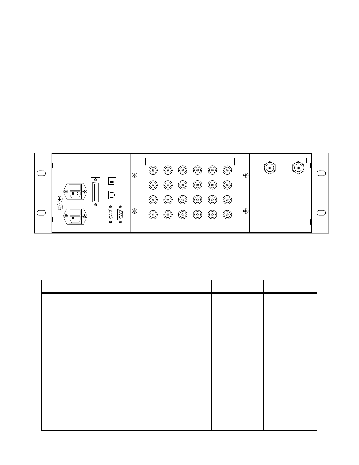
Figure 2-1. Model 9100 Rear Panel
Table 2-1. Rear Panel Connectors and Fuses
REF
DES FUNCTION CHASSIS
CONNECTOR MATING
CONNECTOR
J1 & J2 Connection to GPS antenna. J1 connects antenna to
GPS Reference Module A1and J2 connects antenna to
GPS Reference Module A2.
N female (2) Antenna Lead- in
cable
J3 & J4 (NOT USED)
J5 – J28 Reference Outputs BNC female (24) BNC male
J29 10 BaseT Ethernet (NTS/NTP) RJ45 female RJ45 male
J30 Alarms, Major and Minor RJ45 female RJ45 male
J31 TOD (Time of Day) DB-9 female (2) DB-9 male
J32 RS-232 I/O DB-9 female (2) DB-9 male
J33 Reference Outputs (to Digital Distribution Unit) AMP 554088-1 IEEE-488 Interface
Cable, with metal
shell and shielded
cable, 1 meter.
Cable supplied with
Model 9200
FL1 100 to 240 Vac, power to PS A (A11) IEC-320 type Power Cord
F1 3 amp slow-blow fuse for PS A (A11) and spare fuse Installed in FL1
FL2 100 to 240 Vac power to PSB ( A12) IEC-320 type Power Cord
F2 3 amp slow-blow fuse for PSB (A12) and spare fuse Installed in FL2
E1 FL1/F1
FL2/F2 J33
J29
J30
J31 J32
J25
J26
J27
J28
J21
J22
J23
J24
J17
J18
J19
J20
J13
J14
J15
J16
J9
J10
J11
J12
J5
J6
J7
J8 J2 J1
FREQUENCY OUTPUTS
123456
AAAAAA
BBBBBB
CCCCCC
DDDDDD
AB
GPS ANTENNA
GND
AC INPUT A
AC INPUT B
REFERENCE
OUTPUTS
10
BASE T
ALARMS
TOD RS-232
I/O
LINE
100-240 VAC
1.2A TO 0.7A
48-63 Hz

TRAK MODEL 9100 MODULAR FREQUENCY/TIME SYSTEM
2-3
TM4400013 Rev. D
2-7 MULTI-PIN INTERFACE CONNECTOR
Table 2-2 through 2-5 provide the multi-pin connector pin assignments.
Table 2-2 10 BASE T (J29)
Pin No FUNCTION
1 TXD+ (Transmit Data)
2 TXD- (Transmit Data)
3 RXD+ (Receive Data)
4 N/C
5 N/C
6 RXD- (Receive Data)
7 N/C
8 N/C
Table 2-3 Alarms (J30)
Pin No FUNCTION
1 N/C
2 N/C
3 N/C
4 Minor Alarm Common
5 Minor Alarm N.C.
6 N/C
7 Major Alarm Common
8 Major Alarm N.C.
Table of contents


