Smittybilt 2600i User manual

SMITTYBILT DIGITAL INVERTER GENERATOR | 1
IMPORTANT Please make certain that persons who are to use this equipment
thoroughly read and understand this user’s manual prior to operation
USER’S
MANUAL

2 | SMITTYBILT DIGITAL INVERTER GENERATOR
C O N T E N T S
1.SAFETY INFORMATION........................................................................................ 3
2.CONTROL FUNCTION........................................................................................... 4
3.PRE-OPERATION CHECK ..................................................................................... 6
4.OPERATION ......................................................................................................... 8
5.PERIODIC MAINTENANCE ................................................................................... 12
6.TROUBLE SHOOTING .......................................................................................... 15
7.STORAGE............................................................................................................. 16
8.SPECIFICATIONS ................................................................................................. 17
9.SPECIFIATION...................................................................................................... 18
10. WIRING DIAGRAM............................................................................................ 19
10.REPLACEMENT PARTS ..................................................................................... 20
10.GENERATOR WEARING PARTS LIST ................................................................ 21
10.WEARING PARTS REPLACEMENT INSTRUCTIONS........................................... 22

SMITTYBILT DIGITAL INVERTER GENERATOR | 3
1. GENERATOR LOCATION
• NEVERoperatethegeneratorinsideanybuilding,includinggarages,basements,
crawlspacesandsheds,enclosureorcompartments,includingthegenerator
compartmentofarecreationalvehicleortrailer.
• Pleaseconsultyourlocalauthority.Insomeareas,generatorsmustberegisteredwith
thelocalutility.Generatorsusedatconstructionsitesmaybesubjecttoadditional
rulesandregulations.
• Generatorsshouldbeonaat,levelsurfaceatalltimes,includingtimesofnon-
operation.Generatorsmusthaveatleastvefeetofclearancefromallcombustible
material.Inadditiontoclearancefromallcombustiblematerial,generatorsmust
alsohaveatleastthreefeetofclearanceonallsidestoallowforadequatecooling,
maintenanceandservicing.
• GeneratorsshouldneverbestartedoroperatedinthebackofaSUV,camper,
trailer,inthebedofatruck(regular,atorotherwise),understaircases/stairwells,
nexttowallsorbuildings,orinanyotherlocationthatwillnotallowforadequate
coolingofthegeneratorand/orthemufer.DONOTcontaingeneratorsduring
operation.Allowgeneratorstoproperlycoolbeforetransport,re-fueling,orstorage.
• Placethegeneratorinawell-ventilatedarea.DONOTplacethegeneratornearventsor
intakeswhereexhaustfumescouldbedrawnintooccupiedorconnedspaces.
Carefullyconsiderwinddirectionwhenpositioninggeneratorforoperation.
2. EXHAUST FUMES ARE POISONOUS
• Neveroperatetheengineinaclosedareaoritmaycauseunconsciousness
anddeathwithinashorttime.Operatetheengineinawellventilatedarea.
3. FUEL IS HIGHLY FLAMMABLE AND POISONOUS
• Alwaysturnofftheenginewhenrefueling
• Neverrefuelwhilesmokingorinthevicinityofanopename.
• Takecarenottospillanyfuelontheengineormuferwhenrefueling.
• Ifyouswallowanyfuel,inhalefuelvapor,orallowanytogetinyoureyes,
seeyourdoctorimmediately.Ifanyfuelspillsonyourskinorclothing,
immediatelywashwithsoapandwaterandchangeyourclothes.
• Whenoperatingortransportingthemachine,besureitiskeptupright.
Ifittilts,fuelmayleakfromthecarburetororfueltank.
PLEASE READ AND UNDERSTAND THIS MANUAL COMPLETELY BEFORE OPERATING THE MACHINE.
OUTDOOR USE ONLY!
1. SAFETY INFORMATION

SMITTYBILT DIGITAL INVERTER GENERATOR | 5
(1)Fueltank
(2)Fueltankcap
(3)Fuellter
(4)Carryinghandle
(5)Mufer
(6)Sparkplug
(7)Chokelever
(8)Recoilstarter
(9)Fuelcock
(10)Brakelever
(11)Wheel
(12)Oilllercap
(13)Airlter
(14)Fuelpump
(15)Battery
(16)OilAlert
(17)Overloadindicatorlight
(18)ACpilotlight
(19)Smartthrottle
(20)Infopanel
(21)DCcircuitbreaker
(22)Ignitionswitch
(23)DCreceptacle
(24)Ground(earth)terminal
(25)ACreceptacleL5-30R
(26)ACreceptacle5-20R
(27)Parallelconnectionsocket
(28)Parallelconnectioncontrol
socket
2. CONTROL FUNCTION

6 | SMITTYBILT DIGITAL INVERTER GENERATOR
1. OIL WARNING SYSTEM
Whentheoillevelfallsbelowthelowerlevel,theenginestops
automatically.
Unlessyourellwithoil,theenginewillnotstartagain.
2. ENGINE SWITCH
Theengineswitchcontrolstheignitionsystem.
(1) “ON”(run)
Ignitioncircuitisswitchedon.Theenginecanbestarted.
(2) “STOP”
Ignitioncircuitisswitchedoff.Theenginewillnotrun.
(3) “START”
Startingcircuitisswitchedon.Thestartermotorstarts.
3. SMART THROTTLE SWITCH
WhentheSmartthrottleswitchisturned“ON”,theeconomycontrol
unitcontrolstheenginespeedaccordingtotheconnectedload.The
resultsarebetterfuelefciencyandlessnoise.
4. DC CIRCUIT PROTECTOR
TheDCcircuitprotectorturnsoffautomaticallywhentheload
exceedsthegeneratorsratedoutput.
5. FUEL COCK
Thefuelcockisusedtosupplyfuelfromthetanktothecarburetor.
Reducetheloadtowithinspeciedgeneratorrated
outputiftheDCcircuitprotectorturnsoff.
CAUTION:

SMITTYBILT DIGITAL INVERTER GENERATOR | 7
.6 REMOTE CONTROL SWITCH
Theremotecontrolswitchcontrolstheignitionsystem
“ON”
Thestartermotorstarts.
“OFF”
Theenginewillnotrun.
7. BRAKE LEVER
Thefunctionofbrakeleveristopreventthegeneratorfrommoving.
Brakeleverisnotworking,generatorcanmove.
Brakeleverisworking,generatorcan’tmove.
3. PRE-OPERATION CHECK
1. CHECK ENGINE FUEL
Makesurethereissufcientfuelinthetank.
Iffuelislow,rellwithunleadedautomotivegasoline.
Besuretousethefuellterscreenonthefuellterneck.
Recommendedfuel:87octane+.
Donotusegasolinecontainingmorethan10%ethanol.Gasolinecontaining
higherlevelsofethanoliscorrosiveandattractsmoisture,whichcancausestart
orrunningproblems,andinsomecasesdamagethegeneratorsfuelsystem.
Damagetogeneratorfromethanolenrichedfuelsisnotcoveredbywarranty.
Fueltankcapacity:(seepage17)
Addmorethan1.32galoffuelforthersttimetouse
thismachine.Pre-operationchecksshouldbemade
eachtimethegeneratorisused.
CAUTION:
• Refuelinwell-ventilatedareabeforestartingthegenerator.If
enginehasbeenrunning,allowittocoolbeforerestarting.
• Donotrelltankwhileengineisrunningorhot.
• Closefuelcockbeforerefuelingwithfuel.
• Becarefulnottoadmitdust,dirt,waterorotherforeignobjects
intofuel.
• Donotllabovethetopofthefuellteroritmayoverowwhen
thefuelheatsuplaterandexpands.
• Wipeoffspiltfuelthoroughlybeforestartingengine.
• Keepawayfromopenames.
WARNING:
ON ON
OFF OFF
ON
OFF
①②

8 | SMITTYBILT DIGITAL INVERTER GENERATOR
2. CHECK ENGINE OIL
Makesuretheengineoilisattheupperleveloftheoilllerhole.
Addoilasnecessary.
• Removeoilllercapandchecktheengineoillevel.
• Ifoillevelisbelowthelowerlevelline,rellwith
suitableoiltoupperlevelline.Donotscrewintheoil
llercapwhencheckingoillevel.
• Changeoilifcontaminated.
• Oilcapacity:(seepage17)
• Recommendedengineoil:APIService“SJ”
3. GROUND (Earth)
Makesuretoground(earth)thegenerator.
4.CONNECT BATTERY (for electric starting system)
• Loosenthescrewandremovethebatterycover.
• Clamptheredwiretothepositive(+)terminaland
theblackwiretothenegative(-)terminalofthebattery.
Donotreversethesepositions.
• Besurethebatteryisinstalledonthebatterymounttraysecurely.
• Installthecoverandtightenthescrew.
Recommendedbattery:12V6AH
CAUTION:
UPPER
LEVEL

SMITTYBILT DIGITAL INVERTER GENERATOR | 9
4. OPERATION
1. STARTING THE ENGINE
NOTE: Before starting the engine,
do not connect the electric apparatus.
A Recoil start
1.Turnthefuelcocklevertothe“ON”position.Pressprimerbulb.
2.Turntheengineswitchtothe“ON”or“RUN”position.
3.Turnthechokelevertotheposition.
Notnecessaryiftheengineisstartedusingtheremote.
4.Pullthestarterhandleslowlyuntilresistanceisfelt.Thisisthe
“Compression”point.Returnthehandletoitsoriginalposition
andpullswiftly.Donotfullypullouttherope.Afterstarting,
allowthestarterhandletoreturntoitsoriginalpositionwhilestill
holdingthehandle.Graspthecarryinghandlermlytopreventthe
generatorfromfallingoverwhenpullingtherecoilstarter.
5.Warmuptheengine.
6.Turnthechokeleverbacktotheoperatingposition.
Notnecessaryiftheengineiselectrictype.
7.Warmuptheenginewithoutaloadforafewminutes.
B Electric start
1.Turnthefuelcocklevertothe“ON”position.
2.Turntheengineswitchtothe“START”position.
3.Turnon“CHOKE”.
4.Turntheengineswitchtothe“RUN”position
5.Warmuptheenginewithoutaloadforafewminutes.
6.Turn“CHOKE”off.
Thegeneratorhasbeenshippedwithoutengineoil.Fillwithoil
oritwillnotstart.Donottiltthegeneratorwhenaddingengine
oil.Thiscouldresultinoverllinganddamagetotheengine
WARNING:
ON
STOP
RUN
START
ENGINE
SWITCH

10 | SMITTYBILT DIGITAL INVERTER GENERATOR
4. OPERATION (Continued)
C Remote start
1.Turnthefuelcocklevertothe“ON”position.
2.Turntheengineswitchtothe“RUN”position.
3.Slowlyclickthe“ON”buttontwice.
4.Warmuptheenginewithoutaloadforafewminutes.
2. USING ELECTRIC POWER
1. AC APPLICATION
(a)ChecktheInfopanelforpropervoltage.
(b)Turnofftheswitch(es)oftheelectricalappliance(s)
beforeconnectingtothegenerator.
(c)Inserttheplug(s)oftheelectricalappliance(s)
intothereceptacle.
2. OVERLOAD INDICATOR LIGHT
Theoverloadindicatorlightcomesonwhenanoverloadofa
connectedelectricaldeviceisdetected,theinverterunitoverheats,or
theACoutputvoltagerises.Theelectronicbreakerwillthenactivate,
stoppingpowertothegenerationinordertoprotectthegeneratorand
anyconnectedelectricdevices.Theoutputpilotlight(green)
willickerandtheoverloadindicatorlight(red)willturnon,thenthe
enginewillstoprunning.Ifsopleasefollowthefollowingsteps:
(a)Turnoffanyconnectedelectricdevicesandstoptheengine
(b)Reducethetotalwattageofconnectedelectricdeviceswithinthe
applicationrange.
(c)Checkforblockagesinthecoolingairinletandaroundthe
controlunit.Ifanyblockagesarefound,remove.
(d)Afterchecking,restarttheengine.
Besuretheelectricapparatusisturnedoffbefore
pluggingin.Besurethetotalloadiswithingenerator
ratedoutput.Besurethesocketloadcurrentiswithin
socketratedcurrent.Thesmartthrottleswitchmust
beturnedto“OFF”whenusingelectricdevicesthat
requirealargestartingcurrent,suchasacompressor
orsubmersiblepump.
CAUTION:

SMITTYBILT DIGITAL INVERTER GENERATOR | 11
3. DC APPLICATION (option)
Thisusageisapplicableto12Vbatterychargingonly.
(a)Charginginstructionforbattery
• Disconnecttheleadsforthebattery.
• Loosenbatteryllercap.
• Ifthebatteryuidislowlevel,Filldistilledwatertotheupperlimit.
• Measurethespecicgravityforthebatteryuidbyusingthe
hydrometer,andcalculatethechargingtimeinaccordingwiththe
tableshownonrightside.
• Thespecicgravityforthefullychargedbatteryshallbewithin
1.26to1.28.Itisrecommendedtoconrmeveryanhour.
(b)ConnectbetweentheDCoutputsocketandthebattery
terminalsusingthechargingleads.Theleadsshallbeconnected
makingsureofthe(+)and(-)polarity.
(c)TheDCcircuitprotectoristobesetto“ON”after
conrmingtheconnection,iftheprotectorisin“OFF”position.
ThegeneratorACoutputautomaticallyresetswhentheengine
isstoppedandthenrestarted.Theoverloadindicatorlightmay
comeonforafewsecondsatrstwhenusingelectricdevices
thatrequirealargestartingcurrent,suchasacompressorora
submersiblepump.However,thisisnotamalfunction.
Besurethesmartthrottleswitchisturnedoffwhile
chargingthebattery.
*Alwayschargeperbatterymanufacturerecommendations.
CAUTION:
CAUTION:
3
2
1
FSpecific gravity 68°
3. 47AH 20HR
2. 35AH 20HR
1. 30AH 20HR
Battery capacity
charging time Hr
8 10
4620
1.06
1.14
1.10
1.22
1.18
1.26
1.30
Aim for specific gravity and charging time

12 | SMITTYBILT DIGITAL INVERTER GENERATOR
3. STOPPING THE ENGINE
1. Turnoffthepowerswitchoftheelectric
apparatusordisconnectanyelectricdevices.
2. Turntheengineswitchto“STOP”position.
Clickremoteswitchtothe“OFF”position.
3. Turnthefuelcockleverto“OFF”.
4.Allowenginetocoolbeforerestarting.
STOP
RUN
START
ENGINE
SWITCH
OFF
ON ON
OFF OFF
OFF

SMITTYBILT DIGITAL INVERTER GENERATOR | 13
5. PERIODIC MAINTENANCE
1) MAINTENANCE CHART
Regularmaintenanceismostimportantforthebestperformanceandsafeoperation.Themaintenanceschedule
appliestonormaloperatingconditions.Ifyouoperateyourgeneratorunderunusualorharshconditions,suchas
sustainedhigh-loadorhigh-temperatureoperation,oruseitindustyconditions,serviceintervaltimewilldecrease.
Ifusedindusty/harshenvironments,cleanoutgeneratorbyremovingsidepanelsandusingcompressedair.
Item Remarks Pre-operation
check(daily)
Initial
1month
or20Hr
Every3
months
or50Hr
Every6
months
or100Hr
Every12
months
or100Hr
SparkPlug Checkcondition
adjustgapandclean. •
Replaceifnecessary.
Engine Checkoillevel •
Oil Replace • • •
Oil Cleanoillter •
AirFilter Clean.Replaceif
necessary. •
FuelFilter Cleanfuelcocklter.
Replaceifnecessary •
Choke Checkchoke
operation •
Valve
Clearance
Checkandadjust
whenengineiscold. •
FuelLine Checkfuelhosefor
crackordamage.
Replaceifnecessary.
•
Exhaust
System
Checkforleakage.
Re-tightenorreplace
gasketifnecessary
•
Checkmufer
screen.Clean/
replaceifnecessary.
•
Carburetor Checkchoke
operation •
Cooling
system
Checkfandamage. •
Starting
system
Checkrecoilstarter
operation. •
Idlespeed Checkandadjust
engineidlespeed •
Fittings/
Fasteners
Checkallttingsand
fastenerscorrectif
necessary.
•
Crankcase
breather
Checkbreather
hoseforcracksor
damage.Replaceif
necessary
•
Generator Checkthepilotlight
comeson •
14 | SMITTYBILT DIGITAL INVERTER GENERATOR
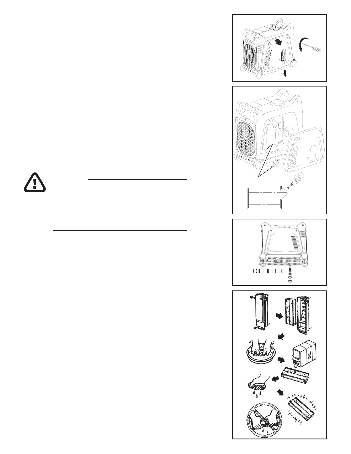
2. ENGINE OIL REPLACEMENT
1.Placethemachineonalevelsurfaceandwarmupthe
engineforseveralminutes.
Thenstoptheengineandturnthefuelcockknobto“OFF””.
2.Loosenthescrewandremovethecover.
3.Removetheoilllercap
4.Placeanoilpanundertheengine.
Tiltthegeneratortodraintheoilcompletely
5.Replacethegeneratoronalevelsurface.
6.Addengineoiltotheupperlevel.
6.5. DO NOT screwindipstickwhencheckingoillevel
7.Installtheoilllercap
8.Installthecoverandtightenthescrew
Recommendedengineoil:(seepage17)
APIService“SJ”
3. AIR FILTER
Maintaininganaircleanerinproperconditionisveryimportant.
Dirtinducedthroughimproperlyinstalled,improperlyserviced,
orinadequateelementsdamagesandwearsoutengines.
Keeptheelementalwaysclean.
1.Removethecover.
2.Removetheairltercoverandelement.
3.Washtheelementinsolventanddry.
4.Oiltheelementandsqueezeoutexcessoil.
Theelementshouldbewetbutnotdripping.
5.Inserttheelementintotheairlter.
6.Installthecover
Besurenoforeignmaterialentersthecrankcase.
Donottiltthegeneratorwhenaddingengineoil.This
couldresultinoverllinganddamagetotheengine
Cleantheoillterevery100hrs.
CAUTION:
OIL FILTER
UPPER
LEVEL
SMITTYBILT DIGITAL INVERTER GENERATOR | 15
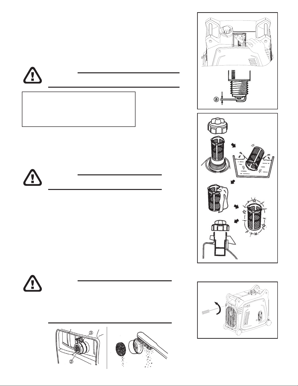
4. CLEANING AND ADJUSTING SPARK PLUG
1.Removethecover.
2.Checkfordiscolorationandremovethecarbon.
3.Checkthesparkplugtypeandgap.
4.Installthesparkplug.
5.Installthecover
5. FUEL TANK FILTER
1.Removethefueltankcapandlter.
2.Cleanthelterwithsolvent.Ifdamaged,replace.
3.Wipethelterandinsertit.
6. MUFFLER SCREEN
1.Removethecover.
2.Removethemuferscreen.
3.Usetheatheadscrewdrivertoprythe
sparkarresteroutfromthemufer
4.Removethecarbondepositsonthemuferscreen
andsparkarresterusingawirebrush.
5.Installthemuferscreen.
6.Installthecover
Besurethetankcapistightenedsecurely.
WARNING:
Aloosesparkplugcanoverheatanddamagetheengine.
WARNING:
Theengineandmuferwillbeveryhotafterthe
enginehasbeenrun.Avoidtouchingtheengineand
muferwhiletheyarestillhotwithanypart
ofyourbodyorclothingduringinspectionorrepair.
WARNING:
Standardelectrodecolor:TanColor
StandardSparkPlug:A7RTCTorch
SparkPlugGap:1.0-1.3mm(0.039-0.051in)

16 | SMITTYBILT DIGITAL INVERTER GENERATOR
6. TROUBLE SHOOTING
(1)Enginewon’tstart
1.FuelsystemsNofuelsuppliedtocombustionchamber.
• Nofuelintank….Supplyfuel.
• Fuelintank….fuelcockknobto“ON”.
• Cloggedfuelline….Cleanfuelline.
cloggedcarburetor….Cleancarburetor.
• Allowhotenginetocoolbeforerestarting.
(2)Engineoilsystem
Insufcient
• Oillevelislow….Addengineoil.
(3)Electricalsystems
Poorspark
• Sparkplugdirtywithcarbonorwet….
Removecarbonorwipesparkplugdry.
• Faultyignitionsystem….Consultdealer.
(4)Compressioninsufcient
• Wornoutpistonandcylinder….Consultdealer.
(5)Generatorwon’tproducepower
Circuitbreaker(AC)to“OFF”…Stoptheengine,thenrestart.
Circuitbreaker(DC)to“OFF”…PresstoresettheDCprotector
(6)Generatoroutputwillbereducedinhighaltitudeconditionsand
whileusingE10fuel.Forbestperformanceusenon-ethanol
blendedfuel.

SMITTYBILT DIGITAL INVERTER GENERATOR | 17
7. STORAGE
Longtermstorage(90+days)ofyourmachinewillrequiresomepreventive
procedurestoguardagainstdeterioration.
Note:Donotuseplasticsheetasadustcover.Anonporouscoverwilltrap
moisturepromotingrustandcorrosion.
1.DRAIN THE FUEL
1.Removethefueltankcap,drainthefuelfromthefueltank
2.Removethecover,drainfuelfromthecarburetorby
looseningthedrainscrew.
2. ENGINE
1.Removethesparkplug,pourinaboutonetablespoonof
SAE10W30or20W40motoroilintothesparkplughole
andreinstallthesparkplug.
2.Usetherecoilstartertoturntheengineoverseveraltimes
(withignitionoff).
3.pulltherecoilstarteruntilyoufeelcompression.
4.Stoppulling.
5.Cleanexteriorofthegeneratorandapplyarustinhibitor.
6.Storethegeneratorinadry,well-ventilatedplace,
withacoverplacedoverit.
7.Thegeneratormustremaininaverticalposition.
8.Removebatteryanduseabatterymaintainerformotorcyclebatteries.
3. SHORT TERM STORAGE
1.Addfuelstabilizerimmediatelytofreshfuelinacanister.Mixwell
beforefuelingupgenerator.
2.Allowgeneratortorunatleast10minutestoallowtreatedgasoline
toreplacetheuntreatedgasolineinthefuelsystem.
3.Turnofffuelvalveandallowgeneratortocontinuerunningtillitruns
outofgasoline.Turnoffgeneratorsignitionsystem.
4.Topofffueltankwithtreatedgasoline.Airinthefueltankwill
promotefueldeterioration.

18 | SMITTYBILT DIGITAL INVERTER GENERATOR
SPECIFICATION
37 kgs/81.6 lbs
0.95 Quarts / 0.9 Liters
24.2”x13.5”x19.9”
25.2”x14.2”x21.3”
40 kgs/88.2 lbs
5.4 HP / 5500 rpm
6.4 Liters / 1.69 gal
4.8 hours (100% load)
6.7 hours (50% load)
149.5 cc

SMITTYBILT DIGITAL INVERTER GENERATOR | 19
Ignition winding
Spring winding
Engine switch
High
pressure
wrap Spark
plug
OUTPUT
Control
winding
Oil sensor
Main
winding
Stepping motor
M
BREAKER
BREAKER
Economic
switch
RECTIFIER
ENGINE SWITCH CONTINUTY
DC
winding
BATTERY
Invert cell
OVERLOAD
LOW OIL
R
R
P
R
R
R
R
R
R
R
R
W
W
W
W
W
W
W
BL
Y/G
Y/G
BU BU
0 0
0
PI
BU
BU
BL
BUBU
Gr
BL
BL
BL
BL
BL
BL
BL BL
BL
BL
BL
BL
BL
BL
BL
BL
BL
GR
BU
Y/G
O
W
R
P
FUSE 3A
FUSE 3A
WIRING DIAGRAM
2600i

20 | SMITTYBILT DIGITAL INVERTER GENERATOR
Part # Description
2786-01 Parallel Cable
2786-02 Spring of oil-lter
2786-03 Oil Strainer
2786-04 Oil Filter
2786-05 Air Filter
2786-06 Fuel Strainer
2786-07 Fuel Filter
2786-08 Fuel Tubes set
2786-09 Spark Arrestor
2786-10 Mufer Gasket
2786-11 Carburetor
2786-12 Recoil Starter
2786-13 Ignition Controller
2786-14 Wireless remote and receiver
2786-15 Starting relay
2786-16 Fuel Pump
2786-17 Battery
2786-18 Gas Cap
2786-19 Handle*2
2786-20 Pull Start side panel
2786-21 Other side panel
2786-22 Rear Panel
2786-23 Wheel
2786-24 Top Panel/door
2786-25 Oil Cap
2786-26 Decal Set
2786-27 Battery hold down strap
2786-28 Ignition Key
2786-29 Spark Plug
2786-30 Choke assy
2786-31 Battery charging cord
2786-32 Inverter assy
2786-33 Ignition coil
2786-34 Control panel assy
2786-35 Wheel's brake
2786-36 Hardware set
REPLACEMENT PARTS

SMITTYBILT DIGITAL INVERTER GENERATOR | 21
No. Item
Qty
(pc/set) Pictures
1Spark plug A7RTC 1
2Oil ller cap Oring 1
3 Oil strainer 1
4Oil lter 1set
5Air lter Assy 1set
6 Fuel strainer 1
7Fuel lter 1
8 Fuel tubes 1
9 Spark attestor 1
10 Mufer gasket 1
11 Carburetor 1set
2786 GENERATOR WEARING PARTS LIST
No. Item
Qty
(pc/set) Pictures
12 R ecoil starter 1set
13 Lgnition controller IC-2500 1
14 Remote& Wireless receiver 1set
15 Starting reply 1set
16 Quadripuntal fuel pump 1set
Note: Customer can easy to replaced all wearing parts.
Table of contents
Popular Inverter manuals by other brands


Tarmo
Tarmo ko1121 quick start guide

Ingeteam
Ingeteam INGECON SUN 3Play 160TL Installation and operation manual

Shinefar
Shinefar SF-1k-TL user manual

Victron energy
Victron energy MultiPlus Compact 12/2000/80-30 230V manual

Xantrex
Xantrex Freedom SW Series owner's guide

Sunways
Sunways STS-1KTL-S user manual