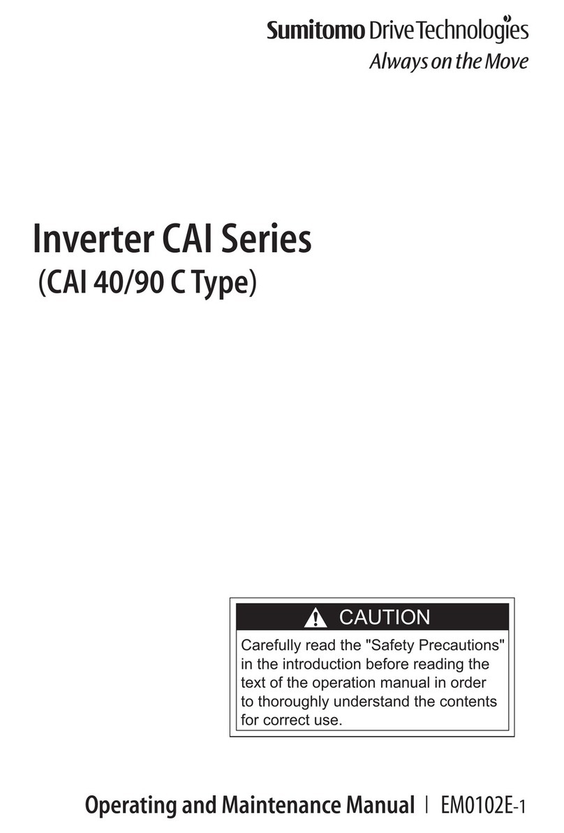
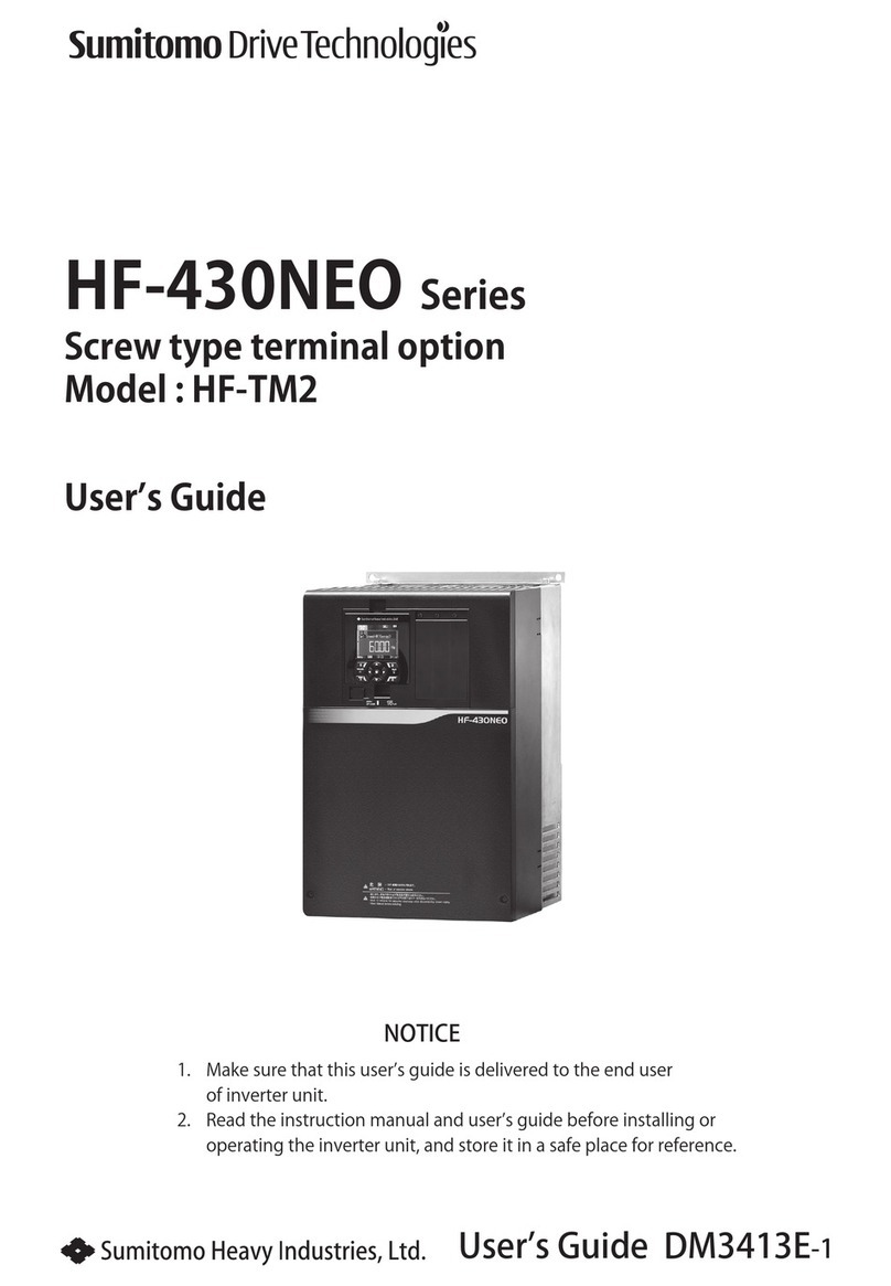
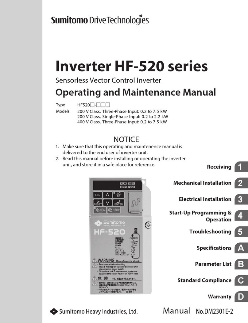
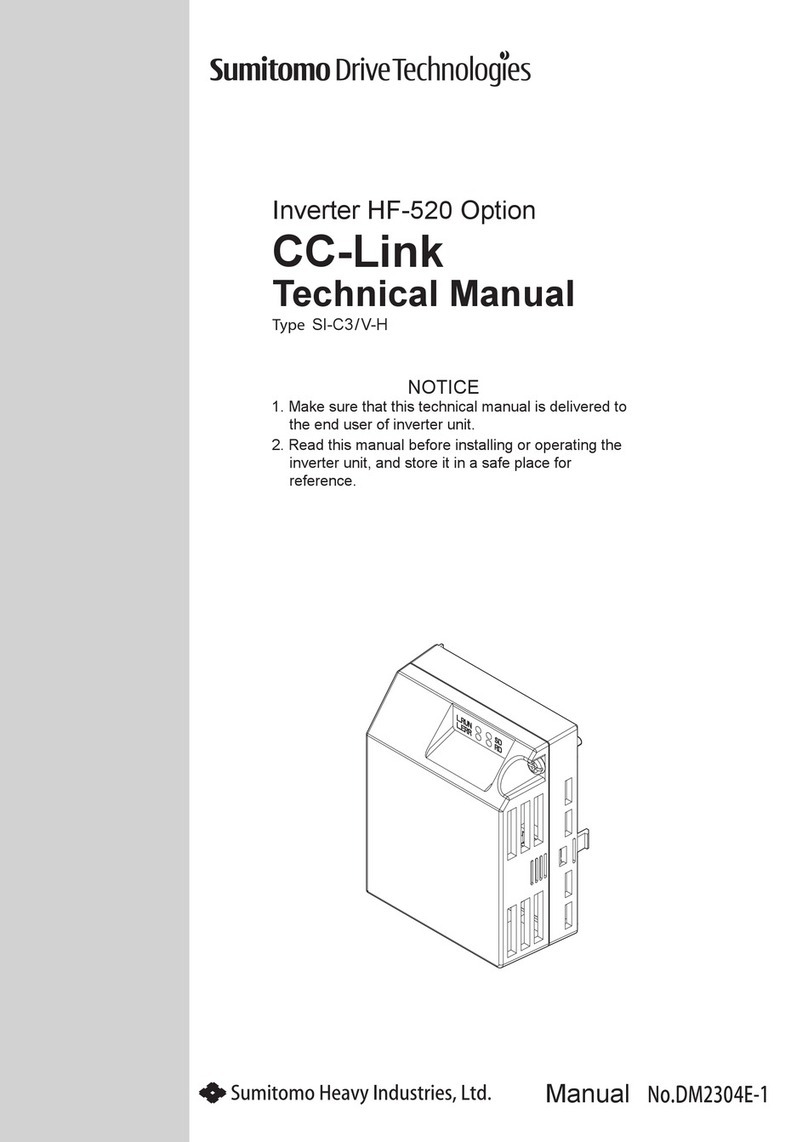
Sumitomo CAI Series User manual

EM0102E-4Operation Manual
Inverter CAI Series
(CAI 40/90 C Type)
CAUTION
Carefully read the “Safety Precautions” in
the introduction before reading the text
of the operation manual in order to
thoroughly understand the contents for
correct use.

[Contents]
Safety Precautions ................................................................................... 1
1. Standard specications.......................................................................... 6
2. Outline drawing........................................................................................ 7
3. Installation.................................................................................................. 8
4. Wiring ........................................................................................................... 10
5. Operation.................................................................................................... 12
6. RS485 Serial Communication ............................................................. 15
7. Alarm output ............................................................................................. 22
8. Maintenance and inspection ............................................................... 23
9. Precautions as to operation.................................................................. 24
10. Safety Guideline........................................................................................27
[Check the contents of packing]
Operation
Manual
Inveter
CAI40C/CAI90C
AC INVERTER

- 1 -
Precautions in general
Covers and safety shields have been removed in the illustrations in
the operation manual in order to show the details. Be sure to return
specied covers and safety shields to the original position before
operation. Operate the inverter in conformity with the operation
manual.
The operation manual is subject to change for improvement of the
product, change in specications, and easy use of the manual itself.
The operation manual No. will be renewed when a revised edition
is issued.
Remodeling of the inverter by the customer is beyond the scope of
our warrantee, and we will not take responsibility for any result of
remodeling.
[ Safety Precautions ]
Carefully read this operation manual for correct use before installation,
operation, maintenance, and inspection. Thoroughly understand the
inverter, safety information, and precautions before use.
Safety precautions are classified into "DANGER" and "CAUTION" in this
manual.
: Improper handling entails danger,
possibly leading to death or serious
injury.
: Improper handling entails danger,
possibly leading to medium-degree or
slight injury or property damage.
Matters classified under CAUTION may also cause serious
results depending on the situation.
Be sure to strictly observe these safety precautions.
DANGER
CAUTION

- 2 -
(1) Conrmation of actual product
CAUTION
Do not operate the machine with a damaged inverter or an inverter
with some missing parts, otherwise injury may result.
(2) Installation
CAUTION
Attach the inverter to metal or other nonammables, otherwise a
re may break out.
Do not place the inverter near inammables, otherwise a re may
break out.
Do not hold the case at the front of the inverter, otherwise the
inverter may drop, leading to injury.
Do not allow metal chips and other foreign substances to enter,
otherwise a re may break out.
Install the inverter on a floor strong enough to withstand the
weight of the inver ter according to the operation manual,
otherwise the inverter may drop, leading to injury.

- 3 -
(3) Wiring
DANGER
Check that the input power is OFF before wiring, otherwise an
electric shock or re may result.
Be sure to install a magnetic circuit breaker (MCB), otherwise a re
may break out.
Be sure to ground the grounding terminal , otherwise an electric
shock or re may result. (200 V-class Type D grounding)
Leave the wiring work to an electric engineer.
Be sure to install the inverter before wiring, otherwise an electric
shock or re may result.
When connecting the emergency stop circuit, be sure to check the
operation of the circuit after wiring, otherwise injury may result.
CAUTION
Do not connect an AC power supply to the output terminals (U, V,
and W), otherwise injury or a re may result.
Check that the voltage of the AC power supply coincides with the
specied input voltage of the inverter, otherwise injury or a re may
result.
Do not subject the inverter to a withstand voltage test, otherwise
semiconductor elements may be broken.
Completely tighten terminal screws, otherwise malfunction, the
inverter breakdown, or a re may result.

- 4 -
(4) Operation
DANGER
Be sure to attach the case cover before turning the power on. Do
not remove the case cover during power supply, otherwise an
electric shock may result.
Do not operate switches with wet hands, otherwise an electric
shock may result.
Do not touch the inverter terminal when power is being supplied
to the inverter although the machine is at rest, otherwise an electric
shock may result.
Trip resetting by turning the power on while the operation signal is
on will make the machine resume operation suddenly. Check that
the operation signal is o before turning the power on, otherwise
injury may result.
CAUTION
Do not touch the die-cast case and radiation fin, which become
very hot, otherwise skin burn may result.
The inverter permits easy operation setting from low to high speed.
Carefully check the allowable range of the motor and machine
before setting, otherwise injury may result.
Prepare a retention brake separately as necessary, otherwise injury
may result.
Do not check signals during operation, otherwise the equipment
may be broken.

- 5 -
(5) Maintenance and inspection
DANGER
This inverter has a high-voltage terminal, which is dangerous. Do
not touch it, otherwise an electric shock may result.
Conduct maintenance or inspection ve minutes or more after the
input power is turned o, otherwise an electric shock may result.
Leave maintenance and inspection to a specialist. Remove
accessories (watch, ring, etc.) before work, otherwise an electric
shock or injury may result.
CAUTION
Semiconductor elements are used in the inverter. Handle the
inverter carefully, otherwise static electricity, etc. may break the
inverter.
Do not change wiring or attach/detach the panel while the power
is supplied, otherwise an electric shock, injury, or equipment
breakage may result.
(6) Others
DANGER
Do not remodel the inverter, otherwise an electric shock, injury, or
a re may result.

- 6 -
1. Standard specications
Product name CAI40C CAI90C
Applicable type of motor 3-phase induction motor
Applicable motor output (W) 25/40 60/90
Specication Conforming to CE mark and cUL
Output rating
Frequency (Hz) 1.0~120Hz Note:1
Output capacity (VA) 106/152 212/303
Output current (A) 0.28/0.4 0.56/0.8
Output voltage (V) Two times for 100 V class input Proportional to
input voltage for 200 V-class input
Input power
source
Voltage (V) Single-phase 100~120 V ±10% or single-phase
200~240 V ±10%
Frequency (Hz) 50/60 ±5%
Input current (A) 0.5~1.5 1.0~3.0
Control
characteristics
Control system PWM control (Pattern: V/F)
Frequency setting Front panel volume or external volume
Torque boost Low : 0 High : 8%
Over load durability 150% output for 1 min.
Acceleration/
deceleration time 0.05~30.0s Note:2
Torque setting High/Low mode setting
Front panel switch Operation stop switch and forward-reverse switch
Set signal external
terminal (8PIN)
Operation stop command, forward-reverse
command, frequency command, free-run input,
and alarm signal output
Protection
function
Details of alarm
Self-diagnosis trip, protection form overvoltage,
protection from instantaneous overcurrent,
protection from undervoltage, protection from
overload, protection of coolant from overheating,
and electronic thermal
Alarm display LED (blinking) for the front panel
Alarm output Open collector
Cooling method Self-cooling
Ambient
condition
Location of installation Indoors, Below 1000m of altitude, without corrosive
gas, liquid, or dust
Degree of contamination 2
Ambient temperature -10°C to +40°C without dew condensation or
freezing
Storage temperature -20°C~60°C
Humidity 90%RH or less
Note: 1. When driving the geared motor, use by frequency setting below the
maximum input speed of the gear.
2. No regenerative circuit for brakes is built in.
- 7 -
60.0
100.0
80.0
φ4.5
80.0
90.0
52.5
137.1
125.18.0
2.7
52.5
AC INVERTER
POWER
ALARM
RS485
RS485
POWER MOTOR
MAX
RUNSTOP
FWD REV
MIN
60.0
100.0
80.0
φ4.5
80.0
90.0
52.5
137.1
125.18.0
2.7
52.5
AC INVERTER
POWER
ALARM
RS485
POWER MOTOR
MAX
RUNSTOP
FWD REV
MIN
1.3
1.3
RS485
Unit: mm
Outline drawing
CAI40C
Weight of unit
0.30kg
CAI90C
Weight of unit
0.47kg
2. Outline drawing

- 8 -
81
+1
0
90
53
+1
0
ACINVERTER
3.1 Installation dimensions/method
Refer to Fig.(a) when installing the inverter. The inverter of the installation
surface as shown in Fig.(b).
(DIN rail cannot be attached.)
Refer to p.7 for the outside dimensions.
Secure the inverter without a gap between the inverter and the mounting
surface by using the mounting hole in the inverter.
Fig.(b)
Fig.(a)
3. Installation

- 9 -
3.2 Place of installation
Install in places with no
corrosive gas or grinding uid.
The inverter is not of a
waterproong structure.
Avoid outdoor use.
Install the inverter in places
without vibration.
Avoid continuous use of
resonance point.
Set the inverter vertically and
provide a space for ventilation
around the inverter.
Avoid hot or humid places or
places with a large quantity of
dust, iron powder, or chips.
The ambient temperature shall
be within the range of -10 to
+40°C.
Avoid direct sunlight.
ACINVERTER
ACINVERTER
10cm
10cm
10cm 10cm
10cm
10cm
5cm 5cm 5cm

- 10 -
4.1 Standard connection diagram
4.2 In the case of sequence
Recommended options
RUN/STOP
FWD/REV
MBS ON
Digital gland
MCB
Input power
Motor output
IM
100V~120V
100V
200V
U/T1
V/T2
W/T3
VRF
COM
RUN
RJ-11
RS-485
Communication port
1: +EV
2: GND
3: SG-
4: SG+
Terminal for control circuit
Terminal for main circuit
CAI Inverter
Shielded wire
(or twisted wire)
6 1
COM
DC48V 50mA
MAX
F/R
MBS
AL
Common
External speed setting signal
+10V10mA (MAX)
Frequency setting unit
VR: 1K~5KΩ
Voltage input
DC 0~10V
4.7KΩ
4.7KΩ
4.7KΩ
+V
+18V
+18V
+18V
N
200V~240V
Alarm output
Natural/braking stop
Forward/reverse rotation
Run/Stop
ON/OFF
External control terminal (8PIN)
Control input signal
4. Wiring
Manufacturer Model Applicable CAI Inverter Model
Magnetic circuit
breaker (MCB)
Mitsubishi
Electric
BL-2C 6A CA140C and CA190C for 200 V input when
60W class motor is used.
BL-2C 6A CA190C for 100V input and 200V input
when 100W class motor is used.
AC reactor Sumitomo
Heavy
Industries
ET682WW-01 All models
Noise lter ET681WW-01 All models
Frequency
setting unit (VR) EVR-01 All models

- 11 -
4.3 Precautions as to wiring
(1) Main circuit
1) Do not connect the power input terminal and motor output
terminals (U, V, and W) reversely.
2) Do not ground the motor output terminals (U, V, and W). Check that
the motor output terminals are not grounded before turning the
power on.
3) Be sure to turn o the power before wiring the main circuit terminal,
grounding terminal, and control terminal or when removing the
wiring.
4) Do not short-circuit the motor output terminals (U, V, and W) with
each other. Check that motor output terminals are not short-
circuited with each other before turning the power on.
5) When operating the inverter, use a magnetic circuit breaker (MCB)
and a thermal relay (TH-RY) as necessary according to the standard
connection diagram. Select a magnetic circuit breaker and a
thermal relay that match the motor rating.
6) The grounding terminal is inverter ground (FG). Use Type D
grounding (100Ω or less; Ø1.6 mm or less).
7) Do not install a power factor improved (phase-advanced) capacitor,
which may be broken by heating because of the high harmonics of
the inverter output.
8) Be sure to use a crimp terminal with insulation sheathing for
connection to the main circuit terminal (100 V, N, 200 V).
(2) Control circuit
1) Do not apply voltage exceeding 48 VDC or current exceeding 50
mA to the output terminal (AL, COM), or do not apply voltage to
reversed polarity.
2) Do not apply voltage to the input terminal (RUN. F/R. MBS) from
outside.
3) When driving the relay directly by the output terminal (AL, COM),
install a ywheel diode (FD).
4) The grounding wire connected to the control circuit must be twisted
or shielded wire.
5) Ground the shield of the shielded wire.
6) Separate the cable to be connected to the control circuit from the
power line.
7) Apply a screwdriver perpendicular to the terminal and tighten the
wire.
CAUTION

- 12 -
5.1 Front panel
POWER LED
Lights while the power is ON.
ALARM LED
Blinks when the protective function
is in operation.
(Refer to p.15 for details.)
Potentiometer
(Refer to p.14 for details.)
RUN and STOP Switch
STOP; RUN
Forward/Reverse Switch
(Usable in the panel mode.
Refer to p.14 for details.)
FWD; REV
5. Operation

- 13 -
Setting
item Switch setting Setting
item Switch setting
Max. output
50Hz
Torque setting
Low-torque output
60Hz
High-torque output
100Hz
Electronic thermal setting
For 40 and 90 W
40W: 0.4A
90W: 0.8A
120Hz
For 25 and 60 W
40W: 0.28A
60W: 0.56A
Reverse rotation control
Reverse rotation
possible
Operation command
source setting
Operation command
control by front panel
Reverse rotation
impossible
Operation command
control by external
terminal
Note: All settings are OFF when the product is shipped.
• Dip switch setting
POWER
ALARM
FWD REV
RUN
STOP
RESET
X1
60Hz
REV EN
LO TQUE
HI THM
PANEL
LOCAL
X2
50Hz
REV DIS
HI
LO
EXT
REMO TE
X1
OFF ON
60Hz
REV EN
LO TQUE
HI THM
PANEL
LOCAL
X2
50Hz
REV DIS
HI
LO
EXT
REMOTE
1.
2.
3.
4.
5.
6.
7.
30
5
0.05 5 10
Unit
Accel/Decel Time(s)
Accel/Decel Time knob(s)
ACC/DES
5
030(S)
Enlarged
view
100%
50Hz
50Hz 100Hz
100%
60Hz
100%
120Hz
100%
60Hz
5.2 Internal panel

- 14 -
< Try to operate >
• When using the front panel for operation
• When using the EXT mode for operation
Front
Step 1
Step 2
Step 3
Step 4
Primary power ON
(Power LED ON)
Determine the direction of
rotation. (FWD or REV)
Set to RUN.
Set the speed of rotation.
(Adjustment using the
potentiometer)
Primary power
Until POWER LED ON
L1: accel/decel set time
L2: Natural stop time
RUN
F/R
MBS
Motor operation
ON
OFF
ON
OFF
ON
OFF
ON
OFF
FWD
STOP
REV
Note: Caution to be exercised when external speed setting is used.
The EXT mode permits the potentiometer on the front panel to control the
speed during external speed control. The set frequency at that time is the
total of respective set frequencies. Set “MIN” when the potentiometer on the
front panel is not used.

- 15 -
Serial communication with the external control device is possible using
the RS485 communication port (RJ11) on the back side for the inverter.
Pin assignment of RJ11 connector
No. Signal Contents Reference
1 +15V +15Vdc Power supply
+15Vdc
2 GND Ground
3 SG– Send/Receive– -
4 SG+ Send/Receive+
5- Unused -
6
6.1 Specications
Items Contents Reference
Transmission speed 9600 bit/s Baud rate
Communication method Half duplex communication
-
Synchronous method Start-stop synchronous communication
Transmission code ASCII Code
Communication method Serial transmission
Compliant interface RS485
Data bit length 7 bits
7, N, 2Parity check None
Stop bit length 2 bits
Starting method One-sided startup method by host-side
command -
Waiting time 10ms
Connection form RS485 1 : 31
Error check LRC checksum 2 bits
6.2 Connection Method
6. RS485 Serial Communication
…
3 4
Inverter1
Controller
・PC
・PLC etc.
Upto63unitscanbeconnectedthecontrollerusingRS485serialcommunication.
Inverter2 Inverter63
3 4 3 4

- 16 -
6.3 Setting for the Inverter Address (DIP Switch)
For RS485 communication, set the DIP switch 7 to ON.
(In this case, you will not be able to drive on the front panel and
terminals.)
DIP switch 1 to 6 is used to set the inverter address.
Refer to the following setting example.
RS485 communication (DIP switch 7: ON)
・For address = 1 (See the right table.)
(20×1) + (21×0) + (22×0) + (23×0) + (24×0) +
(25×0) = 1
・For address = 23
(20×1) + (21×1) + (22×1) + (23×0) + (24×1) +
(25×0) = 23
・For address = 63
(20×1) + (21×1) + (22×1) + (23×1) + (24×1) +
(25×1) = 63
Note: When the control mode is switched to the front panel or the terminal, the
address is stored in the memory. (DIP switch 7: OFF)
When the parameter is reset, the address remains in the memory.
In the case of setting for the new address, DIP switch 7 is ON after power OFF.
Resetting the address and start the inverter.
6.4 Communication Procedure
Communication between the controller and the inverter is performed as
follows.
Reply data ②from the inverter will be replied after receiving data ①.
The inverter does not have active output.
No.
DIP Switch Address
Setting
OFF
(×0)
ON
(×1)
125
2 24
3 23
4 22
5 21
6 20
7 RS485
Waitingtime:10ms
Controller
CAIInverter
① TransmissiondatafromthecontrollertoCAIinverter
② TransmissiondatafromCAIinvertertothecontroller
①
②

- 17 -
6.5 Communication Protocol
6.5.1 Frame Format Transmitted and Received
STX Start data ‘
:
’ (ASCII code/3AH)
ADR1 Communication address:
Address information of 8 bits×2 that composes ASCII code
ADR0
CMD1 Command code:
Command information of 8 bits×2that composes ASCII code
CMD0
DATA (n-1) to 0
Data structure:
8 bits×n data that composes ASCII code of 2n
(n ≦25, ASCII code =50 Max.)
LRC CHK1 LRC Checksum:
8 bits×2 checksum that composes ASCII code
LRC CHK0
END1 END data: END1 =CR
(0DH)
, END0=LF
(0AH)
Note: ADR (Communication address) →Specify the inverter address 1 to 63.
CMD (Command code), DATA (Data format depends on CMD.)
CMD = 03H →Read Data, CMD = 06H →Write Data
Example
Command code 03H: Reading N data (1 to 12)
Ex. Reading 2 data from address 2102H for the
inverter (Address 1)
Command code 06H: Writing 1 data
Ex. Setting the frequency for the inverter (Address 1)
Frequency setting address: 2001H
60Hz(Decimal…6000 →Hexadecimal…1770H)
Transmission message Receive message Transmission message Receive message
STX ‘ : ’ STX ‘ : ’ STX ‘ : ’ STX ‘ : ’
ADR1 ‘0’ ADR1 ‘0’ ADR1 ‘0’ ADR1 ‘0’
ADR0 ‘1’ ADR0 ‘1’ ADR0 ‘1’ ADR0 ‘1’
CMD1 ‘0’ CMD1 ‘0’ CMD1 ‘0’ CMD1 ‘0’
CMD0 ‘3’ CMD0 ‘3’ CMD0 ‘6’ CMD0 ‘6’
Starting
data
address
‘2’
Number of
data (Byte)
‘0’ Data
address
‘2’
Data
address
‘2’
‘1’ ‘0’ ‘0’
‘0’ ‘4’ ‘0’ ‘0’
‘2’ ‘1’ ‘1’
Number of
read data
‘0’
2102H
‘1’
Data
‘1’
Data
‘1’
‘7’
‘0’ ‘7’ ‘7’ ‘7’
‘0’
‘0’
2103H
‘0’ ‘7’ ‘7’
‘0’
‘2’ ‘0’ ‘0’ ‘0’
‘0’
LRC CHK1 ‘D’ LRC CHK1 ‘7’ LRC CHK1 ‘5’ LRC CHK1 ‘5’
LRC CHK0 ‘7’ LRC CHK0 ‘1’ LRC CHK0 ‘1’ LRC CHK0 ‘1’
END1 CR END1 CR END1 CR END1 CR
END0 LF END0 LF END0 LF END0 LF

- 18 -
6.5.2 Parameter Table
Address Parameter Name R/W Data Contents Setting Data
(Decimal) Initial
Setting Recognition code of the
inverter RDepend on the
inverter
- #
0001 Rated current R # . #
0002 Parameter reset R/W Reset 10 0
0003 Max. output frequency
setting R/W
50Hz 0
1
60Hz 1
100Hz 2
120Hz 3
0004 Acceleration/Deceleration
time R/W 0.05 to 30 (s) 5~3000 500
0005 Reverse setting R/W Reverse NG 0 1
Reverse OK 1
0006 Torque setting R/W High 0 1
Low 1
0007 Electronic thermal R/W 25/60 (W) 0 1
40/100 (W) 1
0008 Communication address R 1 to 63 01~63 1
0009 Software version R Depend on the
inverter - # . #
0010 Min. output voltage R/W 1.5 to 20.0 (V) 15~200 15
0011 Torque boost R/W 3.0 to 8.0 (V) 30~80 80
0012 Terminal function setting R/W
RUN: FWD/STOP 0
1
RUN: REV/STOP
RUN: RUN/STOP 1
F/R: FWD/REV
Note: R (Read), W (Write)
This manual suits for next models
2
Table of contents
Other Sumitomo Inverter manuals

Sumitomo
Sumitomo HF-520 Series User manual

Sumitomo
Sumitomo HF-430NEO Series User manual

Sumitomo
Sumitomo HF-430 Series Operating instructions

Sumitomo
Sumitomo HF-520 Series User manual

Sumitomo
Sumitomo HF-520 Series Operating instructions

Sumitomo
Sumitomo CAI40C User manual

Sumitomo
Sumitomo SF-320 User manual