SOLINTEG OGS-3.6K User manual

Integ ON-GRID Inverter
O
OGS-3.6/4.2/5/6K
User Manual
ENGLISHV ERSION

CONTENTS

CONTENTS
1.1 How To Use This Manual………………………………………………………… 5
1.2 Target Groups …………………………………………………………………… 5
1.3 Symbols …………………………………………………………………………… 5
2.1 Safety Notes ……………………………………………………………………… 7
2.2 Statement ………………………………………………………………………… 7
3.1 System Introduction …………………………………………………………… 9
3.2 Product Introduction ………………………………………………………… 10
……………………………………………………… 13
3.4 Unpacking and Storage ……………………………………………………… 14
4.1 Location ………………………………………………………………………… 16
………………………………………………………… 18
5.1 Electrical Wiring Diagram ……………………………………………………
5.2 AC Connection ………………………………………………………………… 23
5.3 PV String Connection ………………………………………………………… 26
5.4 Monitoring Device Installation ……………………………………………… 30
5.5 RMK and CT Installation ……………………………………………………… 31
5.6 Communication Connection ………………………………………………… 32
6.1 App Preparation ………………………………………………………………
6.2 Inspection Before Commissioning…………………………………………… 40
6.3 Commissioning Procedure …………………………………………………… 40
……………………………………………………………… 41
7.1 Main Window……………………………………………………………………
7.2 General Setting ………………………………………………………………… 43
7.3 Advanced Setting ……………………………………………………………… 45
……………………………………… 46
7.5 Auto-Test ……………………………………………………………………… 46
2 Safety Instructions ……………………………………… 7
1 About This Manual ……………………………………… 5
3 Product Description……………………………………… 9
4 Installation ………………………………………………… 16
5 Electrical Connection …………………………………… 21
6 Commissioning …………………………………………… 40
7 Screen Operation ………………………………………… 42

4
User Manual
OGS-3~6K
7.6 Reactive Power Regulation Mode …………………………………………… 48
8.1 Monitoring Device …………………………………………………………… 51
8.2 Cloud monitoring App………………………………………………………… 52
9.1 Error Message ………………………………………………………………… 53
………………………………………………………… 56
10.1 Technical Parameters………………………………………………………… 58
10.2 Contact Information ………………………………………………………… 60
CONTENTS
8 Monitoring ………………………………………………… 51
9 Troubleshooting ………………………………………… 53
10 Appendix ……………………………………………… 58

5
User Manual
OGS-3~6K
About This Manual
-
-
ucts.
not constitute any express or implied guarantee.
1
7.6 Reactive Power Regulation Mode …………………………………………… 48
8.1 Monitoring Device …………………………………………………………… 51
8.2 Cloud monitoring App………………………………………………………… 52
9.1 Error Message ………………………………………………………………… 53
………………………………………………………… 56
10.1 Technical Parameters………………………………………………………… 58
10.2 Contact Information ………………………………………………………… 60
latest manual can be found at www. solinteg.com.
※
※
This manual is applicable to electrical installers with professional qualifications and
①
with hazards.
②Knowledge of the manual and other related documents.
③Knowledge of the local regulations and directives.
Indicates a hazard with a high level of risk that, if not avoided, will result
DANGER
Indicates a hazard with a medium level of risk that, if not avoided, could
WARNING
※ 1.1 How To Use This Manual
※ 1.2 Target Groups
※ 1.3 Symbols
6
User Manual
OGS-3~6K
Indicates a hazard with a low level of risk that, if not avoided, could
CAUTION
Indicates a situation that, if not avoided, could result in equipment or
NOTICE
NOTE

7
User Manual
OGS-3~6K
Safety Instructions
2
①Before installation, please read this manual carefully and follow the instructions in this
manual strictly.
② Installers need to undergo professional training or obtain electrical-related professional
qualication ceicates.
③ When installing, do not open the front cover of the inveer. Apa from peorming work
at the wiring terminal (as instructed in this manual), touching or changing components
without authorization may cause inju to people, damage to inveers and annulment of
the warranty.
④ All electrical installations must conform to local electrical safety standards.
⑤ If the inveer needs maintenance, please contact the local designated personnel for
system installation and maintenance.
⑥ To use this inveer for power generation needs the permission of the local power supply
authority.
⑦The temperature of some pas of the inveer may exceed 60° C during operation. To
avoid being burnt do not touch the inveer during operation. Let it cool before touching it.
⑧ When exposed to sunlight, the PV array generates dangerous high DC voltage. Please
operate according to our instructions, or it will result in danger to life.
①
②
③Damages caused by installation and use of equipment by non-professionals or untrained
personnel.
④Damages caused by failure to comply with the instructions and safety warnings in this
document.
⑤Damages of running in an environment that does not meet the requirements stated in
this document.
⑥
※ 2.1 Safety Notes
※ 2.2 Statement

8
User Manual
OGS-3~6K
⑦ Damages caused by unauthorized disassembly, alteration of products or modication of
software codes.
⑧ Damages caused by abnormal natural environment (force majeure, such as lightning,
eahquake, re, storm, etc.).
⑨ Any damages caused by the process of installation and operation which don't follow the
local standards and regulations.
⑩ Products beyond the warranty period.

9
User Manual
OGS-3~6K
※
-
-
rent and feeds the AC current to the utility grid.
Product Description
3
Figure 3-1 Schematic diagram of PV grid-connected system
Figure 3-2 Applicable grid types
※ 3.1 System Introduction
TN-S TN-C TN-C-S TT
L L L
N N N
N
PE PE
PE
PEN
Transformer Transformer Transformer Transformer
OGS-3~6K OGS-3~6K OGS-3~6K OGS-3~6K
PV
MODULES INVERTER
002456
UTILITY METER
FOR BILLING
PURPOSES
UTILITY
GRID
LOAD
10
User Manual
OGS-3~6K
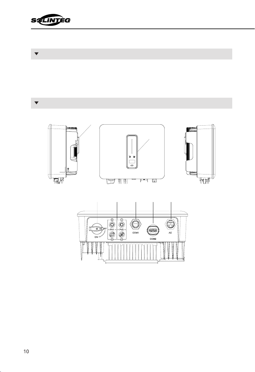
3.2.2 Appearance
3.2.1 Models
3.2 Product Introduction
1
2
3 4 5 67
34 5 6 7
11
User Manual
OGS-3~6K
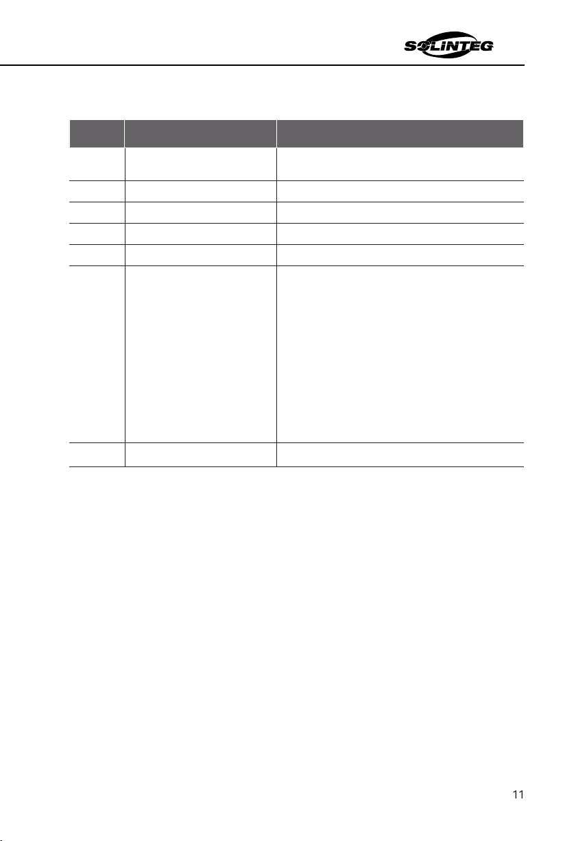
Item Terminal Note
1
2 Hanger
3 DC switch (Optional)
4 DC input terminal PV connector
5
6
There are two versions of the COM2 connector, please
select the appropriate version according to the order
7 Used for On-grid output cable connection

12
User Manual
OGS-3~6K
3.2.3 Indicator
Item Indicator Status Description
1Power and
.
Blue
2
Indicator
3Communica-
tion Indicator
Green Always on The inveer communication is running nor-
mally.
Green Flashing The inveer communicates with datalogger
or Solinteg RMK through RS485.
4
5 Button
1
32
4
5

13
User Manual
OGS-3~6K
Symbol Description
of the presence of hazardous substances in electrical and electronic equipment,
※ 3.3SymbolsOntheInveer
14
User Manual
OGS-3~6K
-
after receiving the device.
accessories in the packing box are complete when receiving the goods.
※ 3.4 Unpacking and Storage
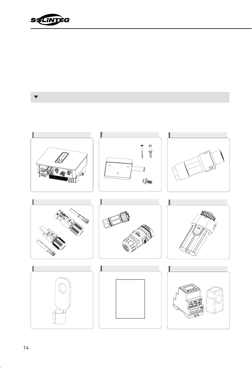
3.4.1 Packing List
DEF
GHI
ABC
Basic
Extened
User
Manual
15
User Manual
OGS-3~6K
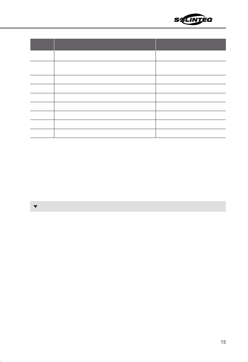
Item Name and Quantity Note
B
(3pcs), M5 screws (1pcs)
C
D PV terminal (2 pairs)
COM2 connector set (1pcs) * Two versions
F Monitoring device (1pcs)
H User guide
I Optional
-
cording to the order requirements.
-
①Do not dispose of the original packing case. It is recommended to store the device in the
original packing case when the device is decommissioned.
②
③
than 8 levels.

16
User Manual
OGS-3~6K
Installation
4
※
-
①
②
③
-
sure to sunlight and rain.
④-
nance.
⑤
⑥
children.
※ 4.1 Location
4.1.1 Installation location
-
formance.
①
②-
tenance.
Figure 4-1 Recommended installation location
WARNING

17
User Manual
OGS-3~6K
4.1.2 Installation Spacing
Figure 4-2 Recommended installation spacing
4.1.3 Installation Angle
Figure 4-3 Permitted and prohibited mounting positions
500mm
300mm 300mm
500mm
500mm
500mm
300mm

18
User Manual
OGS-3~6K
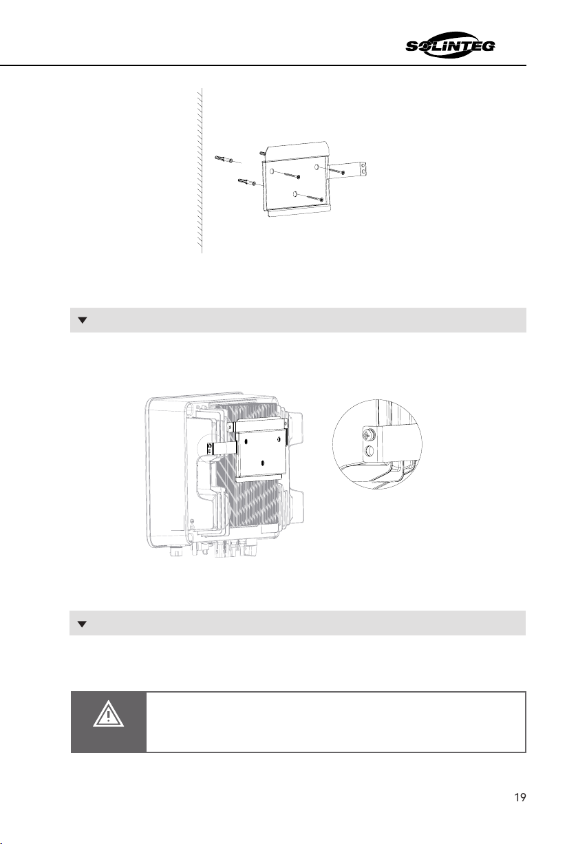
※ 4.2MountingtheInveer
4.2.1 Wall Bracket Installation
Figure 4-4 Dimensions of wall bracket
Figure 4-5 Marking hole position using installation bracket
①Use the wall bracket as the template to mark the position of 3 holes on the wall.
②Use an electrical driller with 10mm diameter bit to drill 3 holes in the wall with 80mm depth.
WARNING
③
wall with expansion screws by using a cross screwdriver.
1
4
4
45
120
19
User Manual
OGS-3~6K
Figure 4-6 Fixing the wall bracket
with M5 screws.
protection. Please always remember to wiring the PE wire before wiring other wires.
4.2.3 External Ground Connection
DANGER

20
User Manual
OGS-3~6K
NOTICE
①
②Fix the grounding terminal to the PE wire with a proper tool and lock the grounding ter-
Figure 4-8 Grounding terminal connection
This manual suits for next models
3
Table of contents
Other SOLINTEG Inverter manuals

SOLINTEG
SOLINTEG M Series User manual

SOLINTEG
SOLINTEG INTEG M MHS Series User manual

SOLINTEG
SOLINTEG MHT-4-20K Series User manual

SOLINTEG
SOLINTEG Integ M Operating manual

SOLINTEG
SOLINTEG MHT-25-50K User manual

SOLINTEG
SOLINTEG INTEG M MHT Series User manual

SOLINTEG
SOLINTEG MHS-3K-30 User manual

SOLINTEG
SOLINTEG INTEG M MHS-3-8K-30 User manual


