EnerSys PowerSafe TS User manual

Sustainable Solutions
PowerSafe®TS
Operation Guide for Solar Applications
2
1. Introduction
1.1. Benets
The specic benets of PowerSafe® TS batteries for renewable
energy applications are as follows.
• Cycling (one “cycle” consists of a discharge, of any depth,
followed by a recharge)
• Overcharge ability
• Cycling in state of discharge
• Low rate of self-discharge
• Large electrolyte reserve
PowerSafe® TS cells are designed for applications where the battery
may undergo repeated cycling with daily depths of discharge of up
to 35% of capacity C120 (such as rural settlements, communications
systems and lighting systems etc.).
1.2. Cell Design
The PowerSafe TS range of single cells offers high performance,
long-life solutions for renewable energy applications.
PowerSafe TS cells are based on proven vented technology and
designed for renewable energy applications that require maximum
cycle life with the highest level of reliability. They are particularly
suitable for use in solar energy installations, ensuring a continuity of
electrical supply during the hours of darkness or during periods of
reduced sunshine.
The Powersafe TS are ooded batteries consuming water and
require regularly maintenance watering (see section 5).
Demineralised water needs to be added at intervals which depends
on operating conditions and electrolyte reserve.
Reduced maintenance is achieved through the use of additional
electrolyte, which means cells only have to be topped-up once a
year. This helps to keep down maintenance costs and makes them
an ideal solution for many remote or unmanned locations.
Tubular positive plates are widely used in batteries for particularly
demanding applications. In the TS range they have been optimised
to give an extended cycle life and increased capacity.
Note operating
instructions
Danger. Cells are
heavy.
Make sure they are
safely installed. Only
use suitable transport
and lifting equipment
Risk of explosion or re.
Avoid short circuits
When working on
batteries, wear safety
glasses and
protective clothing
Electrical hazard
Wash all acid splash
in eyes or on skin with
plenty of clean water and
seek immediate medical
assistance
No smoking.
Do not allow naked
ames, hot objects
or sparks near the
battery, due to the risk
of explosion or re
Electrolyte is highly
corrosive
.
Used batteries contain valuable recyclable materials. They must not be disposed of with the domestic waste but as
special waste. Modes of return and recycling shall conform to the prevailing regulations in operation at the site where
the battery is located.
Safety precautions
Batteries give off explosive gasses. They are lled with dilute sulphuric acid, which is very corrosive. When working with sulphuric acid,
always wear protective clothing and glasses. Exposed metal parts of the battery always carry a voltage and are electrically live (risk of short
circuits). Avoid electrostatic charge. The protective measures according to EN 50272-2 and IEC 62485:2010 must be observed.
Recycling and disposal of used batteries
Warranty
Any of the following actions will invalidate the warranty - non-adherence to the Installation, Operating and Maintenance Instructions.
Repairs carried out with non-approved spare parts. Applications of additives to the electrolyte. Unauthorised interference with the
battery.
Handling
TS batteries are supplied lled & charged
or moist charged, and must be unpacked
carefully to avoid short-circuit between
terminals of opposite polarity. The
cells are heavy and must be lifted with
appropriate equipment.
Keep Flames Away
Discharge any possible static
electricity from clothes by touching
an earth connected part.
Tools
Use tools with insulated handles.
Do not place or drop metal objects onto the
battery.
Remove rings, wristwatch and metal articles
of clothing that might come into contactwith
the battery terminals.
3
1.3. Features & Benets
• Capacities from 300Ah to 4580Ah at the 120 hour rate
• Products available lled & charged or moist charged
• Up to 5200 cycles to 25% depth of discharge
• Minimal maintenance required (topping-up required only once
a year)
• Excellent operational safety including fully insulated connectors
and terminals, acid-proof ame arrestor plug for each cell and
protection of polarities during transport
1.4. Capacity
Capacity is the number of Ah a battery can supply for a well-dened
current and an end of discharge voltage.
Capacity varies with the discharge time, discharge rate and
temperature.
Example:
Capacities for PowerSafe TYS 5 cell are as follows:
Discharge time 50h 100h 120h
End voltage 1.85Vpc 1.85Vpc 1.85Vpc
Capacity at 25°C 739Ah 790Ah 802Ah
The nominal capacity of PowerSafe® TS cells for renewable energy
applications is as follows:
Capacity
Ah Current
ADischarge
period h End voltage
V/cell
C120 I120 120 1.85V
Discharge rate:
Is the ratio of discharge current divided by battery capacity.
Depth of discharge (DOD):
Capacity removed from the battery compared to total capacity.
It is expressed as a percentage. The battery will be sized for solar
applications with a DOD <80% for the autonomy required.
Daily cycle:
The battery is normally used with a daily cycle as follows:
Charge during the day hours and discharge during night hours.
Typically daily use is between 2 to 20% DOD.
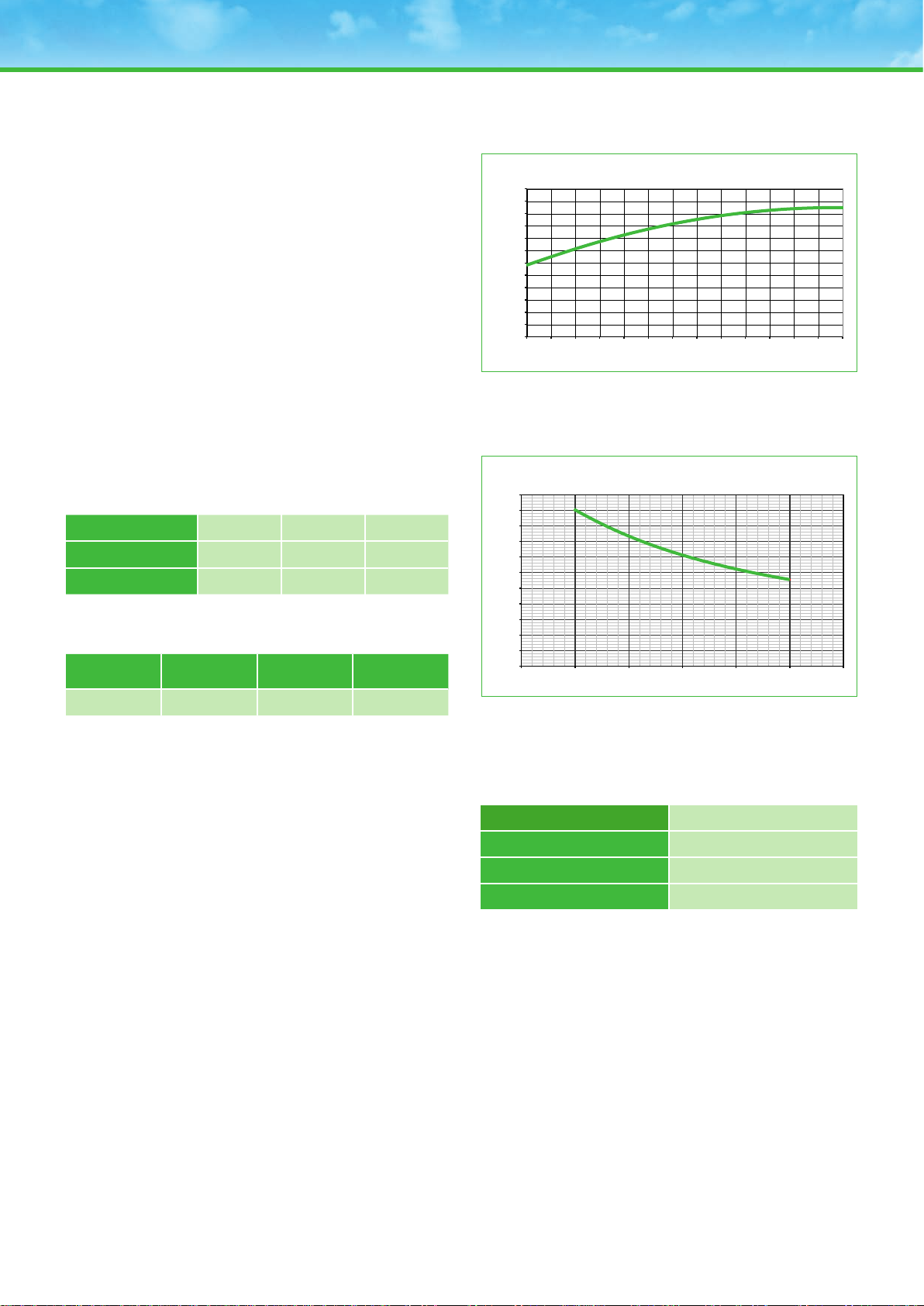
1.5. Effect of Temperature
On the capacity:
Correction factors of the capacity according to the temperature are
shown in the following curve. If the temperature is different from
25°C, correction factors must be applied to the installation rating in
order to secure an optimum service life.
On the number of cycles:
A rise in temperature brings about a decrease in the number of
cycles (see below).
1.6. Charge efciency
The charge efciency is the ratio between the quantity of Ah
delivered during the discharge and the quantity of Ah necessary to
restore the initial state of charge.
State of charge (SOC) Ah Efciency
90 > 85
75 > 90
<50 > 95
0.00
0.10
0.20
0.30
0.40
0.50
0.60
0.70
0.80
0.90
1.00
1.10
1.20
-20 -15 -10 -5 0 5 10 15 20 25 30 35 40 45
Compensation coefficient for a
120 hr. Discharge to 1,85Vpc at 25°C
Temperature in °C
Batteries for renewable energy applications
Effect of temperature on capacity
Batteries for renewable energy applications
Derating factor for number of cycles vs average cell temperature
0.00
0.10
0.20
0.30
0.40
0.50
0.60
0.70
0.80
0.90
1.00
1.10
20 25 30 35 40 45 50
Temperature in °C
Derating Factor
Derating Factor for Number of Cycles vs Average Cell Temperature
Effect of Temperature on Capacity

4
2. General Operating Instructions
2.1. Operating Temperature Range
The maximum operating temperature range for PowerSafe® TS
technology is -10°C to +45°C (humidity <90%).
Optimum life and performance are achieved at +25°C.
All technical data relate to the rated temperature of +25°C.
2.2. Storage
Store the battery at a dry, clean and preferably cool and frost-free
location. Do not expose the cells to direct sunlight,
otherwise defects on container and cover might occur.
Limit values for storage conditions: temperature range of -20°C to
+45°C, humidity <90%.
Self-discharge:
It is the capacity loss that results when the battery is left at rest
(without charge) for a given period of time.
The self discharge will increase:
• With natural ageing of the cell
• Following faulty use such as excessive over-discharge, bad
maintenance, by non-demineralised water topping-up
• Temperature rise
The self-discharge rate of PowerSafe TS batteries with the
temperature:
Temperature 25°C 30°C 40°C
Monthly self-discharge rate 3% 4.5% 10%
PowerSafe TS technology has a shelf life of 5 months when stored
at 25°C. Higher temperatures increase the rate of self discharge and
therefore reduce storage life.
This table gives the maximum storage period before refresh, at the
given average storage ambient temperature:
Average storage
ambient temperature Maximum storage time
20ºC 6 months
25ºC 5 months
30ºC 4 months
40ºC 2 months
PowerSafe TS batteries must be given a refreshing charge:
a. when maximum storage time is reached, or
b. when the OCV approaches 2.10Volts/cell whichever occurs rst
(OCV = Open Circuit Voltage, it is the voltage measured (between
the terminals) when the cell is disconnected from any circuit (zero
current))
If the batteries are supplied moist-charged, the storage time shall
not exceed 2 years. For lling see special instructions on lling and
commissioning moist-charged batteries.
2.3. Freshening Charge
The refresh charge should be conducted using constant voltage
(adjusted to the temperature) eg. 2.23Vpc at 20-25°C with 0.1 C10
Amps current limit for a minimum period of 96h.
Alternatively, a refresh charge can be conducted applying a constant
voltage of 2.40Vpc for 24-48h maximum.
2.4. Commissioning
Please note that the commissioning of moist-charged PowerSafe
TS cells should be carried out in accordance with the instructions
published in our dedicated moist-charged manual.
Safety, installation & ventilation
The battery room should be well ventilated in order to remove
gases produced during charging.The gases (mixture of oxygen
and hydrogen) liberated by the cells when on charge may cause
an explosion, and therefore, care must be taken not to produce
SPARKS: NAKED LIGHTS must be not allowed, and remember NO
SMOKING.
Following precautions must also be taken:
• Do not wear clothing likely to create static electricity (nylon) during
maintenance operations
• Do not use a portable apparatus linked to an electric plug
The electrical protective measures and the accommodation and
ventilation of the battery installation must be in accordance with
the applicable “local” national standards, rules and regulations.
Specically EN 50272-2 and IEC 62485-2:2010 standards apply.
Low ventilation requirement according to EN 50272-2.
The battery should be installed in a clean, dry area.
Avoid placing the battery in a hot place or in front of a window
(no direct sunlight). Battery racks are recommended for proper
installation. Place the cells on the rack and arrange the positive and
the negative terminals for connection according the wiring diagram.
Check that all contact surfaces are clean. Tighten terminal screws,
taking care to use the correct torque loading.
Terminal screw Torque
M10 - female 23 - 25 Nm
Follow the polarity to avoid short circuiting of cell groups. A loose
connector can cause trouble in adjusting the system, erratic battery
performance, and possible damage to the battery and/or personal
injury.
Commissioning
The initial charge is extremely important as it will condition the
battery service life. So the battery must be fully recharged to ensure
that it is in an optimum state of charge.
Case 1:
Using a constant voltage charger.
Cells here will need to be recharged at a constant voltage of
between 2.35 and 2.40 Vpc at 25°C for a minimum of 48h and a
maximum of 72h with a current limited to 0.10C10.

5
Case 2:
With no external source available for recharging.
Connect the battery to the solar panel regulator and leave at rest for
1 to 2 weeks.
For this charge, set the regulator to the following values:
TºC Voltage
Low charge-
restart voltage 0 to 20ºC 2.30V
20 to 40ºC 2.30V
High charge-
disconnect voltage 0 to 20ºC 2.50V
20 to 40ºC 2.45V
End-of-charge
End-of-charge is when all cell voltages and electrolyte specic
gravities (corrected to 25°C) cease to rise for three consecutive
hourly readings.
Continue charging until the specic gravity of electrolyte for all cells
rise to nominal specic gravity at maximum level.
Cell voltages:
Charging rate
(C=Capacity) Minimum voltage in volts per cell for:
15ºC 25ºC 35ºC 45ºC
C/20 2.75 V 2.70 V 2.65 V 2.60 V
C/30 2.70 V 2.65 V 2.60 V 2.55 V
C/45 2.67 V 2.62 V 2.57 V 2.52 V
C/60 2.64 V 2.59 V 2.54 V 2.49 V
Electrolyte specic gravities:
• Measure the specic gravity with a hydrometer
• After reading, squirt the solution back into the cell from which it
was drawn
• The nominal specic gravity at the end of the charge at the
specied level is for a temperature of 25ºC
• If temperature is above or below 25ºC, specic gravity reading
must be adjusted using the table hereunder.
Specific gravity
15ºC 20ºC 25ºC 35ºC 45ºC
1.147 1.144 1.142 1.138 1.131
1.167 1.164 1.162 1.157 1.149
1.186 1.183 1.180 1.176 1.168
1.206 1.203 1.200 1.194 1.187
1.217 1.213 1.210 1.204 1.197
1.227 1.223 1.220 1.214 1.207
1.237 1.233 1.230 1.224 1.216
1.244 1.240 1.237 1.231 1.223
1.248 1.244 1.241 1.234 1.226
1.254 1.250 1.247 1.240 1.232
1.259 1.255 1.252 1.245 1.236
1.270 1.266 1.263 1.256 1.247
Nominal electrolyte specic gravity of PowerSafe® TS cells at
maximum level = 1.240 at 25°C
Values according to electrolyte level at 25°C:
Type Minimum Medium Maximum
TLS, TVS &
TYS 1.280 1.260 1.240
TZS 1.265 1.250 1.240
2.5. Disposal
Lead acid PowerSafe TS batteries are recyclable. End of life
batteries must be packaged and transported according to prevailing
transportation rules and regulations. End of life batteries must be
disposed of in compliance with local and national laws by a licensed
battery recycler.
3. Cyclic Operation
3.1. Cyclic Performance
The graph below shows cycling capability of Powersafe® TS
products (25°C):
End-voltage as a Function of Charge Rate and Temperature
C120 charge rate
Voltage
25ºC
45ºC
35ºC
2.75
2.27
2.65
2.60
2.55
2.50
2.45
0.00 0 0.005 0.010 0.015 0.020 0.025 0.030 0.035 0.040 0.045 0.050
Number of Cycles vs Depth of Discharge
PowerSafe TS® in Renewable Energy Applications
Number of Cycles vs Depth of Discharge
0
500
1000
1500
2000
2500
3000
3500
4000
4500
5000
5500
6000
6500
7000
7500
8000
8500
9000
9500
10000
10500
11000
11500
12000
12500
13000
10 20 30 40 50 60 70 80
Depth of Discharge % @ 25°C
Number of Cycles

6
3.2. Discharging
(low voltage urgent and non-urgent alarm)
As a rule, installations will be equipped with a regulator whose voltage
threshold values will protect against deep discharge:
Discharge time
10h 120h 240h
Low voltage alarm 1.92V 1.92V 1.95V
Disconnect voltage 1.80V 1.85V 1.90V
3.3. Setting Charging Voltages
(solar charge on and solar charge off voltages)
In order to ensure optimum recharge, the following setting charge
disconnect and restart voltages can be applied:
Temperature
-20 to
0ºC 0 to
20ºC 20 to
35ºC > 35ºC
Low recharge-restart
voltage (Vpc) 2.35V 2.30V 2.30V 2.25V
High recharge-dis-
connect voltage (Vpc) 2.50V 2.45V 2.40V 2.35V
For a battery discharged to 80% of its rated capacity within 120
hours, in optimum sunshine it will take around fteen days to
recharge the cells and a further fteen days to equalize their specic
gravity.
4. Service Life
Under normal operating conditions, the battery lifetime largely
depends on the temperature and depths of discharge. The service
life in cycling applications based on the number of years with a daily
DOD can never exceed the design life at 20°C of 20 years.
Inuence of temperature
Example of an Powersafe TS battery cycling with 25% daily:
Average
temperature
of cells
Number of
cycles
at 25°C
Compensation
coefcient
Estimated
average
number of
cycles
at average
temperature
25ºC 5200 15200
30ºC 5200 0.83 4316
35ºC 5200 0.71 3692
Inuence of depth of discharge
See curve (section 3.1), relative to number of cycles according to
DOD at 25°C.
Example of an Powersafe TS battery at 25°C:
Daily depth
of discharge Number of cycles
at 25°C Estimated service
life at 25°C
25 5200 > 14
5.Maintenance, Checks & Data Recording
5.1. Water Consumption
Flooded batteries require maintenance watering.
Water consumption depends on the charging current at a given
temperature.
Example for a battery fully charged with a constant voltage
of 2.35Vpc:
Temperature
25°C 35°C 45°C
Charging current
mA/Ah 14 9
Water consumption
ml/Ah/year 2 10 25
Because there is a large electrolyte reserve, water may be added
just once a year.
Exact watering frequency will be determined by climate conditions
and the battery location.
Top up the electrolyte level (only with demineralised water) to the
nominal level, without exceeding the “max” mark.
5.2. Checks & Data Recording
• The containers and lids should be kept dry and free from dust.
Cleaning must be undertaken with a damped cotton cloth without
additives and without manmade bres or addition of cleaning
agents, never use abrasives or solvents. Avoid electrostatic
charging.
• Every 6 months, check total voltage at battery terminals, cell
voltages & electrolyte specic gravity (electrolyte level &
temperature) of pilot cells, the cells surface temperature and
battery room temperature.
• Once a year, take readings of individual cell voltages too.
• Keep a logbook in which the measured values can be noted as
well as time and date of each event like commissioning date,
water consumption, discharge tests, topping-up dates etc.

7
Notes
TS
www.enersys-emea.com
EnerSys World Headquarters
2366 Bernville Road
Reading, PA 19605
USA
Tel. +1-610-208-1991
Tel. +1-800-538-3627
Fax +1 610-372-8457
EnerSys EMEA
Löwenstrasse 32
8001 Zürich
Switzerland
EnerSys Asia
152 Beach Road
Gateway East Building
Level 11, #11-03
189721 Singapore
Tel: +65 6508 1780
We shall be the best in the industry
by being easy to do business with,
while supplying the highest quality products
and services on time and
in the most cost-effective manner
Publication No. EN-PS-TS-OG-003 - August 2014 - Subject to revisions without prior notice. E.& O.E.
© 2014 EnerSys®. All rights reserved. Trademarks and logos are the property of EnerSys and its affiliates unless otherwise noted.
Table of contents
Other EnerSys Inverter manuals

EnerSys
EnerSys OutBack Power Radian International Series User manual

EnerSys
EnerSys OutBack Power ALPHA OUTBACK ENERGY Radian... Operating instructions

EnerSys
EnerSys OutBack Power Rapid Shutdown Initiator User manual

EnerSys
EnerSys OutBack Power SkyBox User manual

EnerSys
EnerSys PowerSafe OPzV User manual
Popular Inverter manuals by other brands

National Instruments
National Instruments NI 9222 Getting started

Stat-X
Stat-X 30T owner's manual

Hoymiles
Hoymiles HMS-1800-4T Quick installation guide

Radio Shack
Radio Shack 60 Watt Plug-in Power inverter owner's manual

gefran
gefran RADIUS APV 1700-2M-TL-US Installation & operation manual

Western
Western Leonardo Off-Grid 4kW-5000-48 MG user manual


