Shinefar SF-1k-TL User manual

1
User Manual
-Installation
-Operation
SF-1k-TL
SF-2k-TL
SF-1.5k-TL

2
Catalog
1. ............................................................................................................................. 4Notes on this manual
1.1 ........................................................................................................................... 4Scope of Validation
1.2 ................................................................................................................................... 4Symbols Used
1.3 ..................................................................................................................................... 5Target Group
2. ............................................................................................................................................. 6Preparation
2.1 ............................................................................................................................. 6Safety Instructions
2.2 ................................................................................................. 7Explanations of Symbols on Inverter
3. ...............................................................................................................................9Product Information
3.1 ........................................................................................................................................... 9Overview
3.2 ...................................................................................................................... 10Major Characteristics
3.3 ........................................................................................................................................ 11Datasheet
4. ................................................................................................................................. 13Packing checklist
4.1 ............................................................................................................................... 13Assembly parts
4.2 ....................................................................................................................... 14Product Appearance
4.3 ....................................................................................................................... 15Product Identification
4.4 Further Information..............................................................................................错误!未定义书签。
5. ............................................................................................................................................ 16Installation
5.1 .............................................................................................................................................. 16Safety
5.2 ...................................................................................................................... 16Mounting Instructions
5.3 ............................................................................................................................. 17Safety Clearance
5.4 ........................................................................................................................ 18Mounting Procedure
5.4.1 .............................................................................................................. 18Mounting with bracket
5.4.2 ......................................................................................................... 20Mounting without bracket
5.5 ...................................................................................................................................... 22Safety lock
5.5.1 ....................................................................... 22Safety lock (with the wall mounting bracket)
5.5.2 .................................................................. 22Safety lock (without the wall mounting bracket)
6. .......................................................................................................................... 24Electrical Connection
6.1 .............................................................................................................................................. 24Safety
6.2 ......................................................................................................... 24Overview of Connection Area
6.3 ........................................................................................................................ 25AC Side Connection
6.4 ........................................................................................................................ 27DC Side Connection
6.5 ........................................................................................... 32Communication and Monitoring Device
7. .................................................................................................................................................. 33Display
7.1 ....................................................................................................................................... 33LCD Panel
7.2 .................................................................................................................................... 34LCD Display
7.3 .................................................................................................................................. 36Set Language

3
7.4 ............................................................... 37Instructions of Safety Standard selection when power-up
7.5 ............................................................................................................................. 39State Information
8. ....................................................................................................................... 40Recycling and Disposal
9. ................................................................................................................................... 41Troubleshooting
10. ......................................................................................................................................... 42Abbreviation
1
1. Contact .....................................................................................................................错误!未定义书签。
4
1.Notes on this manual
1.1 Scope of Validation
The main purpose of this User’s Manual is to provide instructions and detailed procedures for
installing, operating, maintaining, and troubleshooting the following three types of New Energy-
Solar Inverters:
1k-TL
1.5k-TL
2k-TL
Please keep this user manual all time available in case of emergency.
1.2 Symbols Used
DANGER
DANGER indicates a hazardous situation which, if not
avoided, will result in death or serious injury.
WARNING
WARNING indicates a hazardous situation which, if not
avoided, can result in death or serious injury or moderate
in
j
ur
y
.
CAUTION
CAUTION indicates a hazardous condition which, if not
avoided, can result in minor or moderate injury.
NOTICE
NOTICE indicates a situation that can result in property
damage, if not avoided.
5
1.3 Target Group
Chapter 1, 2, 3, 4, 7, 8, 9, 10 and Chapter 11 are intended for anyone who is intended to
use Grid Tie Solar Inverter. Before any further action, the operators must first read all
safety regulations and be aware of the potential danger to operate high-voltage devices.
Operators must also have a complete understanding of this device’s features and functions.
WARNING
Do not use this product unless it has been successfully installed
by qualified personnel in accordance with the instructions in
Cha
p
ter 5
,
“Installation”.
Chapter 5 and Chapter 6 are only for qualified personnel who are intended to install or
uninstall the Grid Tie Solar Inverter.
NOTICE
Hereby qualified personnel means he/she has the valid license
from the local authority in:
•Installing electrical equipment and PV power systems
(up to 1000 V).
•Applying all applicable installation codes.
•Analyzing and reducing the hazards involved in
performing electrical work.
•Selecting and using Personal Protective Equipment
(
PPE
)
.
6
2.Preparation
2.1 Safety Instructions2.1 Safety Instructions
.Preparation
DANGER
DANGERdue to electrical shock and high voltage
DONOT touch the operating component of the inverter, it
might result in burning or death.
TOprevent risk of electric shock during installation and
maintenance, please make sure that all AC and DC terminals
are plugged out.
DONOT stay close to the instruments while there is severe
weather conditions including storm, lighting etc.
WARNING
The installation,service ,recycling and disposal of the
inverters must be performed by qualified personnel only in
compliance with national and local standards and
regulations. Please contact your dealer to get the
information of authorized repair facility for any maintenance
or repairmen.
Any unauthorized actions including modification of product
functionality of any form will affect the validation of warranty
service; may deny the obligation of warranty service
accordin
g
l
y
.
NOTICE
Public utility only
The PV inverter designed to feed AC power directly into the
public utility power grid,do not connect AC output of the
device to any private AC equipment.
7
CAUTION
The PV inverter will become hot during operation; please
don’t touch the heat sink or peripheral surface during or
shortly after operation。
Risk of damage due to improper modifications.
Never modify or manipulate the inverter or other components
of the system.
2.2 Explanations of Symbols on Inverter
Symbol Description
Dangerous electrical voltage
This device is directly connected to public grid, thus all
work to the inverter shall only be carried out by
qualified personnel.
DANGER to life due to high electrical voltage!
There might be residual currents in inverter because
of large capacitors. Wait 10 MINUTES before you
remove the front lid.
NOTICE, danger!
This device directly connected with electricity
generators and public grid.
Danger of hot surface
The components inside the inverter will release a log
of heat during operation, DO NOT touch aluminum
housing during operating.
An error has occurred
Please go to Chapter 9 “Trouble Shooting” to remedy
the error.
This device SHALL NOT be disposed of in
residential waste
Please go to Chapter 8 “Recycling and Disposal” for
proper treatments.
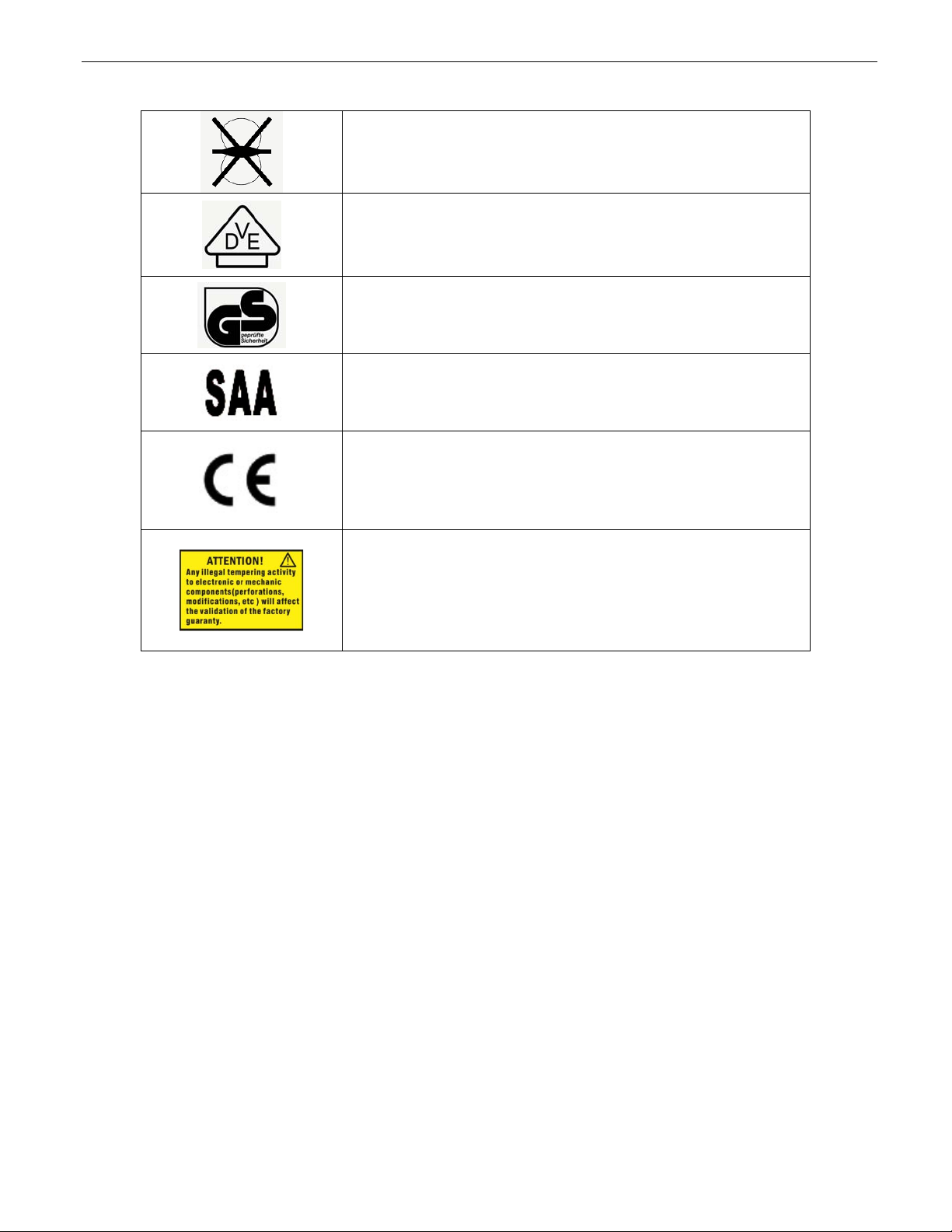
Without Transformer
This inverter does not use transformer for the isolation
function.
German mark of conformity
The inverter complies with the requirement of the
German Grid Regulations.
Certified Safety
The inverter complies with the requirements of the
Equipment and Product Safety Act in Europe.
Standards Association of Australian
The inverter complies with the requirement of the
AS4777.
CE Mark
Equipment with the CE mark fulfils the basic
requirements of the Guideline Governing Low-Voltage
and Electromagnetic Compatibility.
No unauthorized perforations or modifications
Any unauthorized perforations or modifications are
strictly forbidden, if any defect or damage
(device/person) is occurred, shall not take any
responsibility for it.
8
9
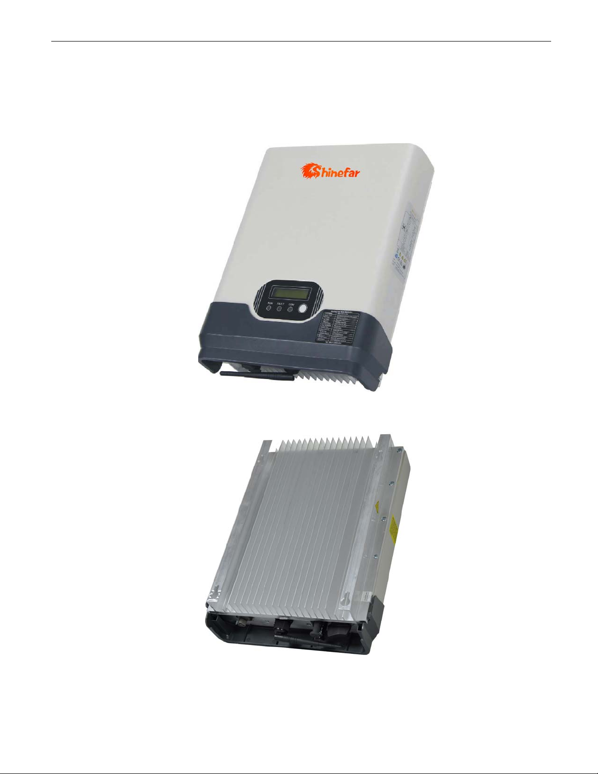
3.Product Information
3.1 Overview
Industrial Layout
Excellent Heat Elimination

10
Effective Shield For DC/AC/Communication Connections
3.2 Major Characteristics
inverter has following characteristics which make inverter “High Efficiency, High Reliability,
High Cost Effective Ratio”
Wide DC input voltage and current ranges, enables more PV panels connected.
Wide MPP voltage range ensure high yield under various weather conditions.
High MPP tracking accuracy, ensure the minimum power loses during converting.
Complete set of protection methods.
Also, following protection methods are integrated in inverter:
Internal overvoltage
DC insulation monitoring
Ground fault protection
Grid monitoring
Ground fault current monitoring
DC current monitoring
Integrated DC switch (Optional)

11
3.3 Datasheet
Type 1k-TL 1.5k-TL 2k-TL
Input (DC)
Max. PV Power 1300W 1750W 2300W
Max DC Voltage 500V 500V 500V
Nominal DC Voltage 360V 360V 360V
Operating MPPT Voltage Range 80-360V 120-450V 120-450V
Start up DC Voltage 90V 150V 150V
Turn off DC Voltage 80V 120V 120V
Max. DC Current 16A 18A 18A
Number of MPP trackers 1 1 1
Number of DC Connection 1 1 1
DC Connection Type MC4 connector MC4 connector MC4 connector
Output (AC)
Max. AC Power 1100W 1650W 2200W
Nominal AC Power (cos phi = 1) 1000W 1500W 2000W
Nominal Grid Voltage 220V/230V/240V 220V/230V/240V 220V/230V/240V
Nominal Grid Frequency 50Hz/60Hz 50Hz/60Hz 50Hz/60Hz
Max. AC Current 5.8A 9.0A 12.0A
Grid Voltage Range* 185-276V 185-276V 185-276V
Grid Frequency Range* 45-55Hz/55-65Hz 45-55Hz/55-65Hz 45-55Hz/55-65Hz
Power Factor >0.99 >0.99 >0.99
Total Harmonic Distortion (THD) <2% <2% <2%
Feed in Starting Power 30W 30W 30W
Night time Power Consumption <1W <1W <1W
Standby Consumption 6W 6W 6W
AC Connection Type Plug-in connector Plug-in connector Plug-in connector
Efficiency
Max. Efficiency (at 360Vdc) 97.5% 97.5% 97.5%
Euro Efficiency (at 360Vdc) 96.3% 96.5% 96.6%
MPPT Efficiency 99.9% 99.9% 99.9%
Safety and Protection
DC Insulation Monitoring Yes
DC Switch Optional
Residual Current Monitoring Unit (RCMU) Integrated
Grid Monitoring with Anti-islanding Yes
Protection Class I (According to IEC 62103)
Overvoltage Category PV II / Mains III (According to IEC 62109-1)
12
Type 1k-TL 1.5k-TL 2k-TL
Reference Standard
Safety Standard EN 62109, AS/NZS 3100
EMC Standard EN 61000-6-1, EN 61000-6-3, EN 61000-6-2, EN 61000-6-4, EN61000-3-2,
EN61000-3-3
Grid Standard VDE 0126-1-1, RD1663, ENEL2010, C10/11, G83/1, UTE C15-712-1, AS4777,
CQC, CEI 0-21
Physical Structure
Dimensions (WxHxD) 330x425x130mm
Weight 13kg
Environmental Protection Rating IP 65 (According to IEC 60529)
Cooling Concept Natural convection
Mounting Information Wall Bracket
General Data
Operating Temperature Range -20°C to +60°C(derating above 45℃)
Relative Humidity 0% to 98%, no condensation
Max. Altitude (above sea level) 2000m
Noise Level <40dB
Isolation Type Transformerless
Display 3 LED, Backlight,16 x 2 Character LCD
Data Communication Interfaces RS485(WiFi, GPRS optional)
Computer Communication RS232 as Option
Standard Warranty 5 Years (10~25 years optional)
*The AC voltage and frequency range may vary depending on specific country grid
13
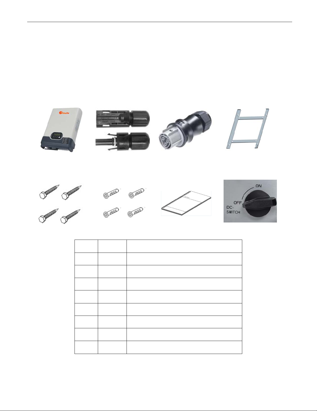
4.Packing checklist
4.1 Assembly parts
After you receive the inverter, please check if there is any damage on the carton, and then
check the inside completeness for any visible external damage on the inverter or any
accessories. Contact your dealer if anything is damaged or missing.
A B C D
E F G H
Object Quantity Description
A 1 inverter
B 1 pair DC connector
C 1 AC connector
D 1 Mounting bracket
E 4 Screw (ST6×50)
F 4 Expansion tube
G 1 Installation and operating instructions
H 1 DC Switch (Optional)

14
4.2 Product Appearance
Front
Object Description
A Removable front shield
B LED light(Green) – RUN
C LED light(Red) – FAULT
D LED light(Yellow) – COM
E Function key for displays and choice of language
F Monitoring LCD with backlighting
Bottom
A B C
15
Object Description
A Plug connectors for DC input.
B RS232/RS485 interface
C Terminal for grid connection (AC output)
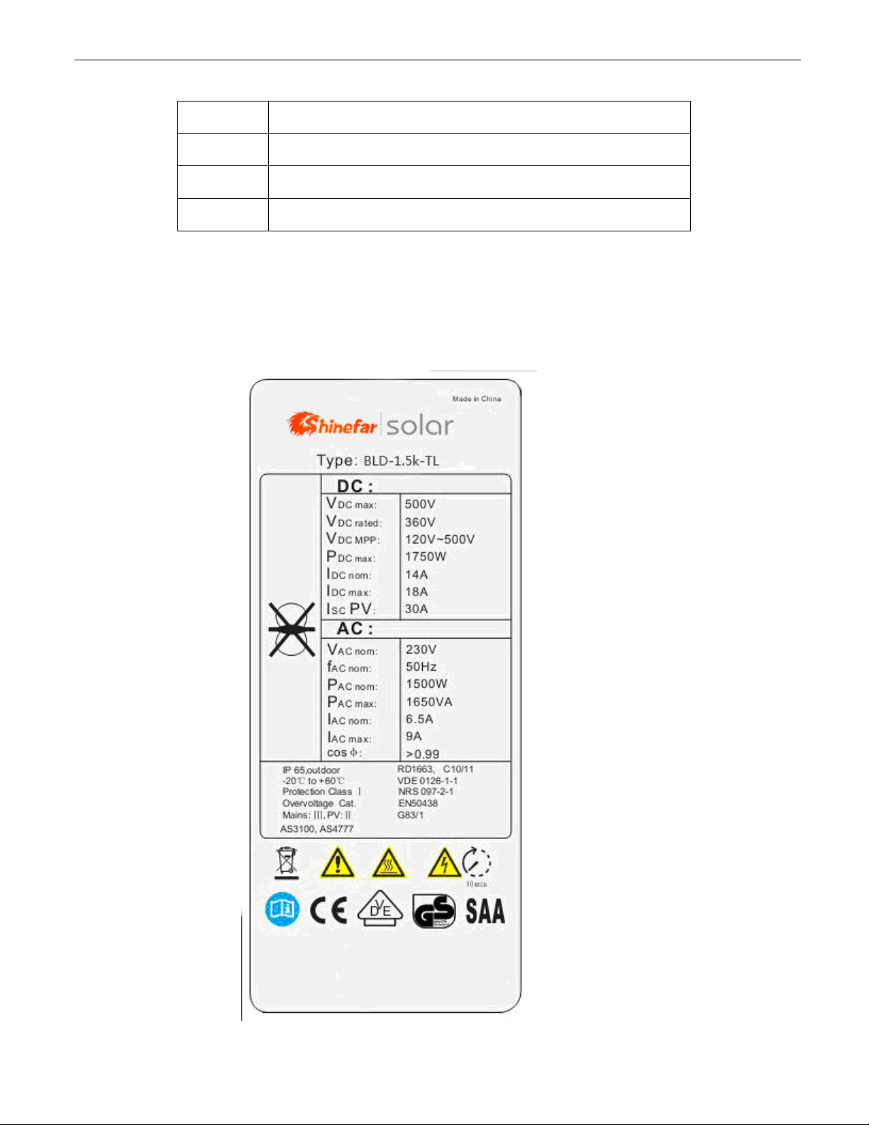
4.3 Product Identification
You can identify the inverter by the side nameplate. Information such as serial number (SN.),
type of the inverter, as well as inverter specifications are specified on the side name plate. The
name plate is on the middle part of the right side of the inverter housing. And the following
figure is the side name plate example as on 1.5k-TL.

16
5.Installation.Installation
5.1 Safety5.1 Safety
DANGER
DANGER to life due to potential fire or electricity shock.
DO NOT install the inverter near any inflammable or
explosive items.
This inverter will be directly connected with HIGH
VOLTAGE power generation device; the installation must
be performed by qualified personnel only in compliance w
national and local standards and regulations.
ith
NOTICE
NOTICE due to the inappropriate or the harmonized
installation environment may jeopardize the life span
of the inverter.
Installation directly expose under intensive sunshine is not
recommended.
The installation site MUST have good ventilation condition.
5.2 Mounting Instructions5.2 Mounting Instructions
M
Ma
ax
x
1
15
5°
°
17
inverter is designed for indoors and outdoors installation
Please mount the inverter in the direction as illustrated above
Install the inverter in the vertical direction is recommended, with a max.15 degrees
backwards.
For the convenience of checking the LCD display and possible maintenance
activities, please install the inverter at eye level.
Make sure the wall you selected is strong enough to handle the screws and bear the
weight of the inverter
Ensure the device is properly fixed to the wall
It is not recommended that the inverter is exposed to the strong sunshine, because
the excess heating might lead to power reduction
The ambient temperature of installation site should be between -20 °C and +60 °C
( between -4 °F and 140 °F )
Make sure the ventilation of the installation spot, not sufficient ventilation may reduce
the performance of the electronic components inside the inverter and shorten the life
of the inverter
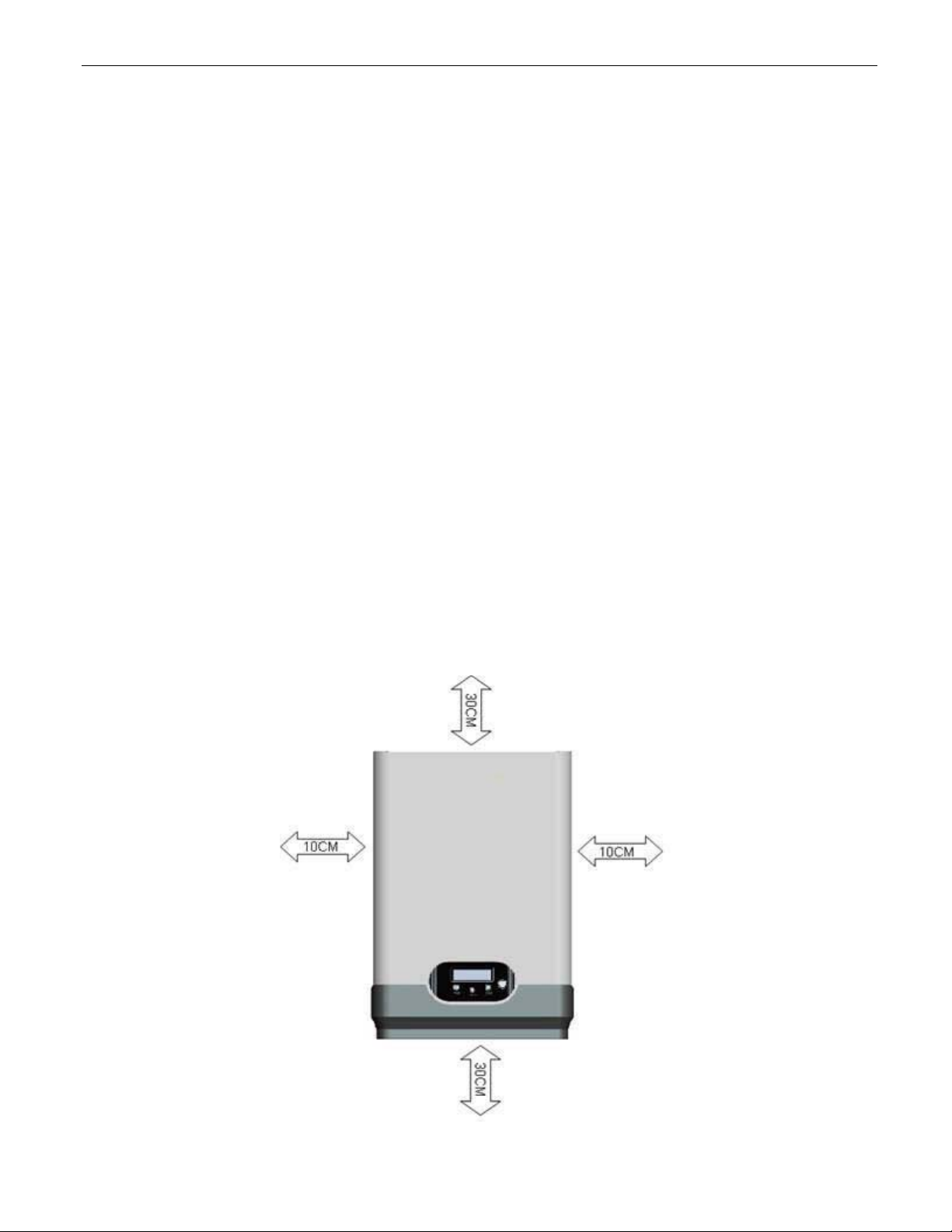
5.3 Safety Clearance
Observe the following minimum clearances to walls, other devices or objects to guarantee
sufficient heat dissipation and enough space for pulling the electronic solar switch handle.
18
Direction Minimum clearance
Above 30 cm
Below 40 cm
Sides 10 cm
5.4 Mounting Procedure
5.4.1 Mounting with bracket
1) Mark 4 positions of the drill holes on the wall according to the wall mounting bracket in
the carton box.
(Depth 50mm)
250
213
First, according to the marks, drill 4 holes in the wall. Then, place four expansion tubes
in the holes using a rubber hammer. Next, make 4 screws through the mounting holes in
the bracket, then tighten the screws into the expansion tubes. So far, the wall mounting
bracket is fixed already.

19
2) First check the 4 holes in the backside of the inverter. Then, lift the inverter carefully,
align the 4 holes in the inverter and the 4 hooks on the bracket, and finally attach the
inverter to the hooks slightly.

20
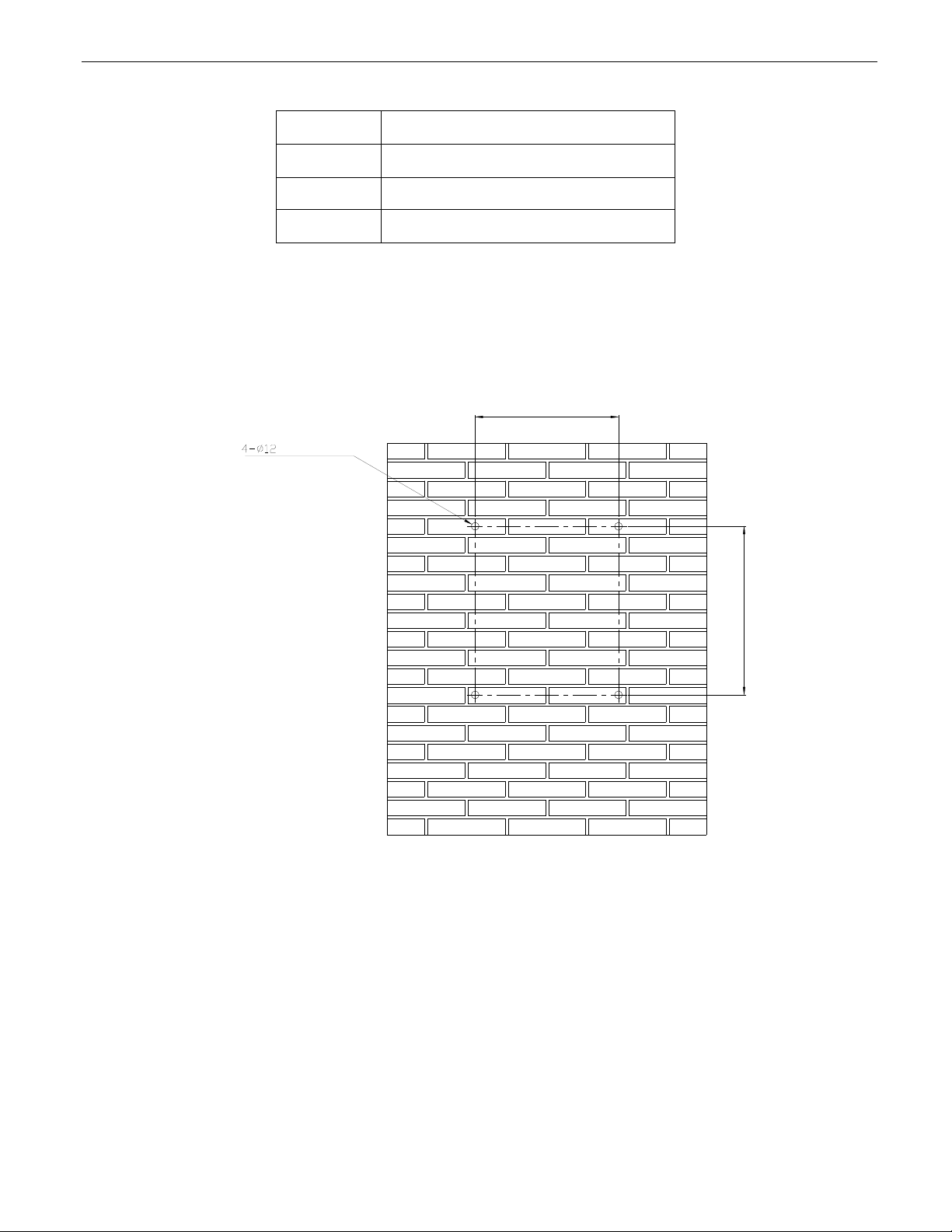
5.4.2 Mounting without bracket
1) Mark 4 positions of the drill holes on the wall according to the paper installation position
scale packed in the carton box.
2
2
5
54
4
±
±1
1
4
4-
-
Φ
Φ
1
1
2
2
3
32
20
0
±
±
2
2
2) First, according to the marks, drill 4 holes in the wall. Then, place four expansion tubes
in the holes using a rubber hammer. Next, wring 4 screws into the expansion tubes.
This manual suits for next models
2
Table of contents
Popular Inverter manuals by other brands

Dometic GROUP
Dometic GROUP WAECO PocketPower SI102 operating manual

Festo
Festo VADM Series operating instructions

Master Battery
Master Battery MasterPower Omega LV 6KW user manual

Generac Power Systems
Generac Power Systems 0K2502SPFR owner's manual

DeWalt
DeWalt DG4300 instruction manual

Victron energy
Victron energy 12 120V manual


