Smokemaster F72 Series User manual

SMOKEMASTER®
MODELS F72A & F72B
INDUSTRIAL ELECTRONIC AIR CLEANER
THE F72 INDUSTRIAL ELECTRONIC AIR CLEANERS INCLUDE COMPONENTS REQUIRED
TO REMOVE AIRBORNE PARTICLES SUCH AS COOLANT MIST, DUST, SOOT, POLLEN,
BACTERIA, TOBACCO AND COOKING SMOKE FROM THE CIRCULATING AIR IN LARGE
RESIDENTIAL, COMMERICAL AND INDUSTRIAL MANUFACTURING FACILITIES. THE AIR
CLEANER IS MOUNTED IN THE RETURN AIR DUCT OF A FORCED AIR SYSTEM WHERE
AMBIENT TEMPERATURE DOES NOT EXCEED 125°F (52°C). ONE OR TWO ELECTRONIC
CELLS, OPERATED BY HIGH VOLTAGE POWER SUPPLIES, REMOVE AIRBORNE
CONTAMINANTS AT EFFICIENCIES AS HIGH AS 99 PERCENT. PERFORMANCE IS
MONITORED BY A STATUS LIGHT ON THE POWER SUPPLY.
xCleans the air at a rate of 1,000 to 12,000 cfm
(1,699 to 20,390 m³/hr.) in forced air systems.
xRated 80 to 99 percent efficient according to
the National Bureau of Standards Dust Spot
Method using atmospheric dust.
xSame high capacity, industrial electronic cell
used in all models.
xReversible electronic cell allows system
airflow to enter cabinet from either side.
xHigh voltage, solid state power supply retains
peak efficiency over a wide range of cell dirt
loading conditions.
xHigh voltage power supply uses voltage
doubler to provide increased ionization
voltage.
xF72 models are available in all single phase
voltages: 100-120 volt, 200-240 volt, 50 or
60 Hz.
xPerformance indicator light and test button
provides operational status.
xStrong, galvanized steel cabinet can be
installed vertically or horizontally.
xHinged power door allows easy access to cells
and filters.

2
TABLE OF CONTENTS
PAGE
SPECIFICATIONS 3
PLANNING THE INSTALLATION 5
Sizing 5
Location 5
INSTALLATION 7
Wiring 8
SERVICE 11
TROUBLESHOOTING 15
PARTS LIST 17
WARRANTY 20

3
SPECIFICATIONS
- IMPORTANT -
THE SPECIFICATIONS GIVEN IN THIS PUBLICATION DO NOT INCLUDE NORMAL MANUFACTURING TOLERANCES.
THEREFORE, THIS UNIT MAY NOT MATCH THE LISTED SPECIFICATIONS EXACTLY. ALSO, THIS PRODUCT IS TESTED
AND CALIBRATED UNDER CLOSELY CONTROLLED CONDITIONS AND SOME MINOR DIFFERENCES IN PERFORMANCE
CAN BE EXPECTED IF THOSE CONDITIONS ARE CHANGED.
MODEL
F72A-1003
F72A-1011
F72B-1003
F72B-1011
NO. OF CELLS
1
1
2
2
RATED VOLTAGE
100-120 Vac
200-240 Vac
100-120 Vac
200-240 Vac
FREQUENCY
50-60 Hz
50-60 Hz
50-60 Hz
50-60 Hz
POWER, NOMINAL
40 Watts
40 Watts
50 Watts
50 Watts
POWER, MAXIMUM
90 Watts
90 Watts
100 Watts
100 Watts
WEIGHT, SHIPPING
200 Lb.
200 Lbs.
300 Lbs.
300 Lbs.
WEIGHT, INSTALLATION
150 Lbs.
150 Lbs.
250 Lbs.
250 Lbs.
AMBIENT TEMPERATURE RATING: Air flow through cells -- 125°F maximum, 40°F minimum
Electronic cells -- 250°F maximum during washing or drying
CABINET: 16 gauge galvanized steel, hinged filter access door
POWER SUPPLY: Solid state, dual voltage power supply provides 9400 Vdc to the ionizer wires and
4700 Vdc to the collector positive plates. The solid state power supply is self-regulating so the output
voltage remains constant over a wide range of cell dirt loading conditions.
ELECTRONIC CELL SPECIFICATIONS, PN 38010:
Dimensions: 24.25” x 24.125” x 10.75” deep
Cell Weight: 60 Lbs.
Collection Area: 240 sq. ft.
Voltage Gradient: 20,000 volts per inch
Ionizer Wires: 11 wires per cell, .010” diameter, tungsten
MOUNTING: a) Vertical, standing or hanging cabinet with horizontal air flow
b) Horizontal mounting with vertical air flow
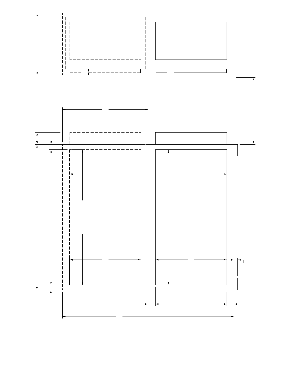
DIMENSIONS: See Fig. 1, Pg. 4
RECOMMENDED AIR FLOW (CFM) WITH CORRESPONDING PRESSURE DROP AND EFFICIENCY RATING
TABLE 1
F72A
F72B
F72B
2 UNITS STACKED
EFFICIENCYa
(PERCENT)
WATER
PRESSURE DROP
cfm
m³/hr.
cfm
m³/hr.
cfm
m³/hr.
in.
kPa
1,000
1,500
2,000
2,500
3,000
1,699
2,548
3,398
4,248
5,096
2,000
3,000
4,000
5,000
6,000
3,398
5,097
6,796
8,495
10,194
4,000
6,000
8,000
10,000
12,000
6,796
10,194
13,592
16,990
20,388
99
99
95
90
80
0.06
0.12
0.22
0.33
0.49
.015
.030
.055
.083
.122
*Efficiency ratings based on National Bureau of Standards Dust Spot Method and American Society of Heating, Refrigerating and
Air Conditioning Engineers Standard 52-76 using atmospheric dust.
4
49.50 F72B
25.50 F72A
29.20
45.38 F72B
21.38 F72A
24.31 DUCT
OPENING
DUCT
OPENING
2.06 2.06
21.00
STACKED
53.50
2.44
58.40
1.19 28.00
MINIMUM
CLEARANCE
FOR CELL
REMOVAL
AND SERVICE
45.38 F72B
21.38 F72A
24.31
2.44
4.10
Figure 1 – F72 INSTALLATION DIMENSIONS

5
PLANNING THE INSTALLATION
- WARNING -
The F72 Industrial Electronic Air Cleaner is not
explosion-proof. It must not be installed where
there is danger of vapor, gas or dust explosion.
INTRODUCTION
Clean air is the subject of numerous laws and
regulations. Typical requirements in the United
States are those put out by the Occupational
Safety and Health Administration (OSHA). Private
groups, such as the American Society of Heating,
Refrigeration and Air Conditioning Engineers
(ASHRAE) have also published numerous
recommendations.
Normally, clean air is defined in regulations and
recommendations as air having a limited amount
of contaminant in it, commonly expressed as parts
per million, or milligrams per cubic meter.
Approved counteractions are intended to lower or
eliminate the amount of contaminants in the air.
One of the more common methods of achieving
this goal is through the use of electronic air
cleaners.
At no time should an electronic air cleaner be
placed where there is a potential for explosion due
to the presence of explosive dusts, gases or
vapors. Contact the nearest Air Quality
Engineering, Inc., representative for assistance in
determining the correct application of an electronic
air cleaner.
AIR CLEANER SIZING
The F72 Induct Air Cleaner is usually sized
according to the capacity of the air handling
system and desired efficiency. See Fig. 4.
LOCATION AND POSITION
Because air-handling systems vary greatly in
arrangement and style, factors such as location,
air distribution, transitions, etc., require careful
consideration.
The F72 can be mounted in a vertical or horizontal
duct. If the air cleaner is to be mounted in a
vertical duct, position the F72 so that the hinged
access door opens down.
TRANSITIONS
When adapting the duct to fit the air cleaner, use
gradual transitions in duct size to prevent
turbulence and to increase efficiency.
Duct transitions should not exceed 20 degrees
(about 4 inches per lineal foot [101.6 mm per lineal
304.8 m]) on each side of a fitting.
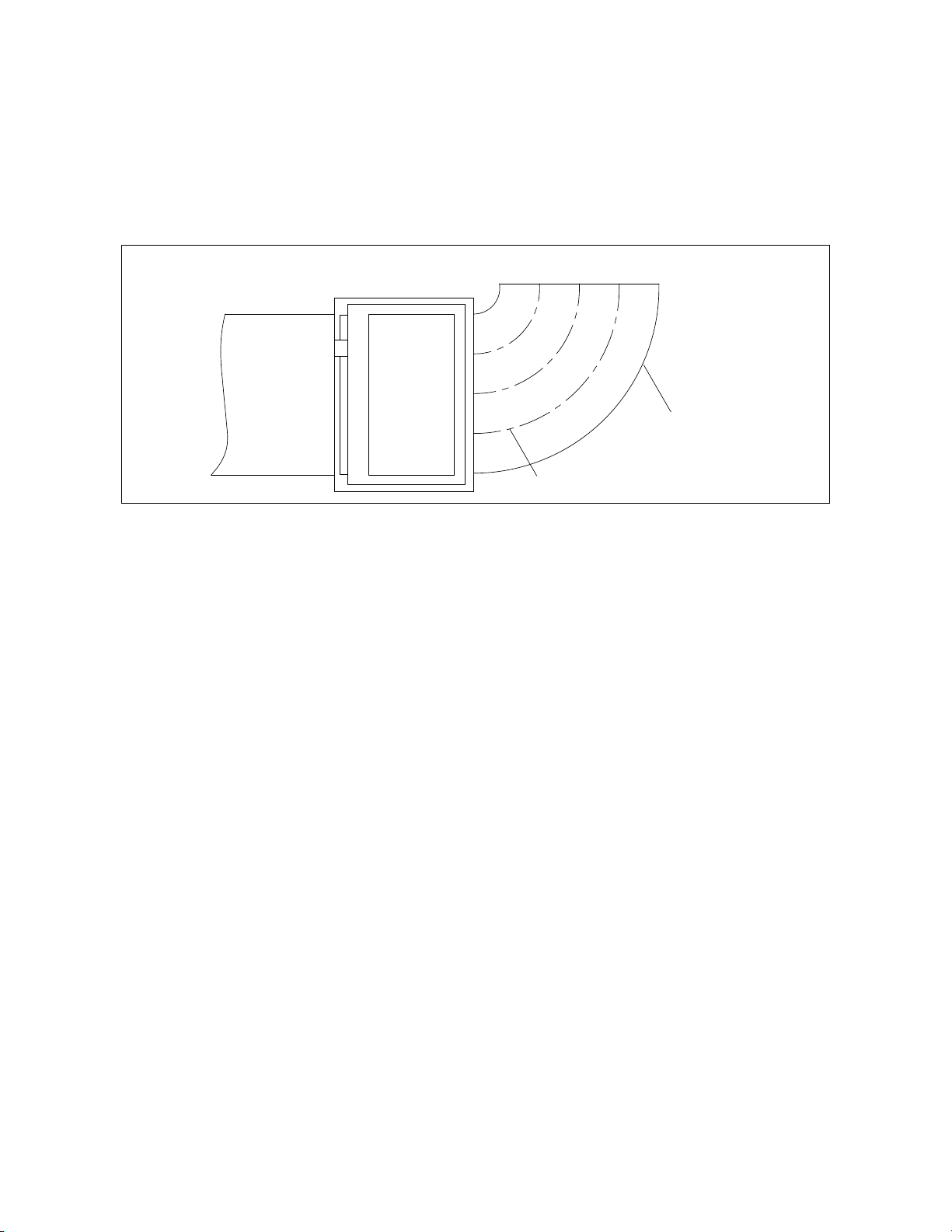
FIGURE 2 –TYPICAL INSTALLATION
OUTDOOR AIR
When outdoor air is added to the return air duct,
sufficient heat must be added to maintain a
uniform air temperature between 50°F and 125°F
[10°C and 52°C]. Two methods are
recommended:
1. Baffles. Mixing baffles should be used to mix
the outdoor air and the return air before it
enters the air cleaner.
2. Preheat Coil. If a large amount of outdoor air
is used, it must be heated. An appropriate
control system should be used to control the
heating element (electric strip heater, steam
coil, etc.)
Outdoor air intakes should be protected to prevent
the introduction of unnecessary contaminants.
Depending on the installation, it may be necessary
F72 ELECTRONIC
AIR CLEANERS
STACKED
AIR
DUCT
AIR
DUCT
6
to incorporate some or all of the precautions
mentioned below.
1. Air intakes should be hooded or louvered to
provide adequate protection from rain and
snow. The type of hood used will depend
upon the installation and expected weather.
2. Air intakes should always be equipped with a
“bird screen.”
At times, it may be desirable to install a prefilter
ahead of the electronic air cleaner. This is done to
remove contaminants that could be harmful to the
air cleaner or might cause excessively fast dirt
buildup or arcing in the electronic cell.
FIGURE 3 –TYPICAL INSTALLATION WITH TURNING VANES IN THE AIR DUCT.
COMMERCIAL APPLICATIONS
When deciding on the number of air cleaners
required for applications such as a restaurant,
bowling alley, store, bar or lounge, several
conditions must be considered. They are:
1. Air to be cleaned of dust, tobacco smoke,
greases, etc. These conditions may require a
higher efficiency in the electronic air cleaner
installation.
2. Capacity (cfm or m³/hr.) of equipment and
system.
3. Method of circulation must be forced air
distributed evenly to all parts of the controlled
area with the required air changes per hour.
4. Maximum number and average number of
people that will occupy controlled area.
5. The percent operating efficiency required of
the electronic air cleaner. The F72 efficiency
should be from 85 to 95 percent depending on
the application and purpose (see Efficiency
Chart, Fig. 4).
INDUSTRIAL APPLICATIONS
Sizing is determining how many air cleaning units
are required to maintain a desired level of air
quality. The process of sizing an industrial
application involves roughly figuring the number of
air cleaners needed and then modifying the figures
according to the specific characteristics of each
application.
For ambient air cleaning, the estimated number of
electronic air cleaners may be determined by the
relationship of air volume to the needed air
changes per hour.
An alternative method for calculating the estimated
number of electronic air cleaners can be used if it
is possible to measure the generation rate of the
contaminants and the allowable level of
contamination. To use either method of
calculation, consult your local sales
representative.
Regardless of the method used to calculate the
number of units needed to produce clean air, the
physical conditions of the space to be cleaned
may either limit this number or demand that more
units be installed. For ambient air cleaning, it is
important to establish a uniform airflow pattern
throughout the entire space. Limitations to the
calculated sizing may be a lack of space for
mounting areas or the number of units may
interrupt normal building operation; that is, a unit
cannot be mounted where an overhead crane will
F72 ELECTRONIC
AIR CLEANER
AIR
DUCT
TURNING VANES
RETURN
AIR DROP
DUCT

7
smash into it or where stand mountings seriously
interrupt building traffic patterns. The number of
units required by air volume and air changes per
hour might need to be increased when the shape
of a structure is such that effective capturing and
air distribution is not possible according to the
sizing calculations.
FIGURE 4 –F72 ELECTRONIC AIR CLEANER CAPACITY AND EFFICIENCY.
AIR CONDITIONING
Make certain the cooling coil is installed
downstream from the air cleaner cabinet to
prevent condensation and chilled air (cooler than
50°F [10°C]) from entering the cell.
HUMIDIFIERS
Location of the system humidifier is important to
the operation of the air cleaner. An evaporative-
type humidifier may be installed between the
furnace warm air duct and the return air duct
without affecting the electronic air cleaner. An
atomizing-type humidifier should be installed
downstream from the air cleaner. If the atomizing-
type humidifier is installed upstream, mist, salts
and minerals may decrease the efficiency of the
electronic cell and create a need for equipment
service.
When the atomizing-type unit must be used
upstream from the F72, the following precautions
should be taken:
1. It must be installed as far from the air cleaner
as possible.
2. A standard, disposable-type furnace filter
should be installed between the humidifier and
the air cleaner to trap water droplets and
mineral salts.
3. The electronic cell must be washed frequently
to prevent a mineral deposit buildup.
INSTALLATION
WHEN INSTALLING THIS PRODUCT
1. Read these instructions carefully. Failure to
follow them could damage the product or
cause a hazardous condition.
2. Check the ratings given in the instructions and
on the product to make sure the product is
suitable for your application.
3. Installer must be a trained, experienced
service technician.
4. After installation is complete, check out
product operation as provided in these
instructions.
- CAUTION -
Disconnect the power supply before installation to
prevent electrical shock and equipment damage.

8
- IMPORTANT -
This section includes information for the sheet metal and electrical installation. Make certain each person
involved with the installation is aware of the appropriate subsections in the manual.
INSTALLATION CHECKLIST
xTransitions
xComponents Assembled
- electronic cells
- power door
xTurning Vanes
xCheck Packing Materials Before Discarding
xWiring
SHEETMETAL INSTALLATION
Air Distribution and Duct Work
The F72 operates most efficiently when all of the
system air is delivered across the electronic cell at
a uniform velocity. Turning vanes should be
added to any return airdrop upstream from the air
cleaner (Fig. 3).
Gradual transitions to the F72 cabinet are
recommended in all duct work larger or smaller
than the cabinet opening. If transitions are used,
they should not exceed 20 degrees (4 in. rise per
linear ft. [101.6 mm rise per linear 304.8 m]).
INSTALL AIR CLEANER
Mount the F72 air cleaner as follows:
1. Fabricate and install the necessary vanes and
transitions.
2. Set the cabinet in position. If hanging
brackets are used, make certain the brackets
are strong enough to hold the cabinet and the
cabinet is attached firmly to the brackets.
NOTE: Place a spirit level on top of the cabinet
to make sure it is level.
3. a. Drill holes for sheet metal screws into the
cabinet face and also the duct.
b. Fasten the duct to the inside of the cabinet
flange opening with sheet metal screws.
c. Seal all joints in the return air system to
prevent dust from entering the clean air
stream.
Install the F72 components as follows:
FIGURE 5 –CORRECT CELL POSITION IN
THE F72
1. Slide the prefilter(s) and post filter(s) into
place.
2. Insert the electronic cell(s) into the cabinet
with the cell handle facing the door opening.
Make certain the arrow stamped on the cell(s)
points downstream (Fig. 5).
WIRING
- CAUTION -
Disconnect the power supply before installation to
prevent electrical shock and equipment damage.
9
4700 VDC COLLECTOR
POWER SUPPLY
HIGH VOLTAGE
OUTPUT: 9400 VDC IONIZER
100 Watts Max
INPUT: 120 VAC 50-60 Hz or
240 VAC 50-60 Hz
Units are not dual voltage
The line voltage supplied to the F72 air cleaner
must match the voltage rating stamped on the
front of the air cleaner.
- CAUTION -
Only persons qualified to install electrical wiring
should attempt this procedure. All wiring must
comply with applicable codes and ordinances.
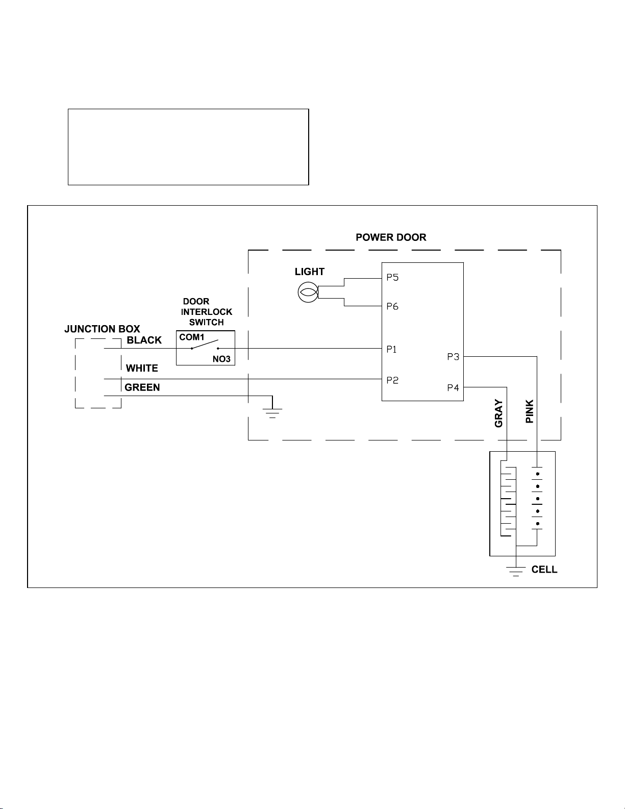
A complete internal schematic diagram of the F72
is shown in Figs. 6 and 7. Figs. 8 and 9 show
typical hookups. Fig. 10 shows typical hookups to
three phase voltage sources.
Figures 6 & 7 – F72 SCHEMATIC
10
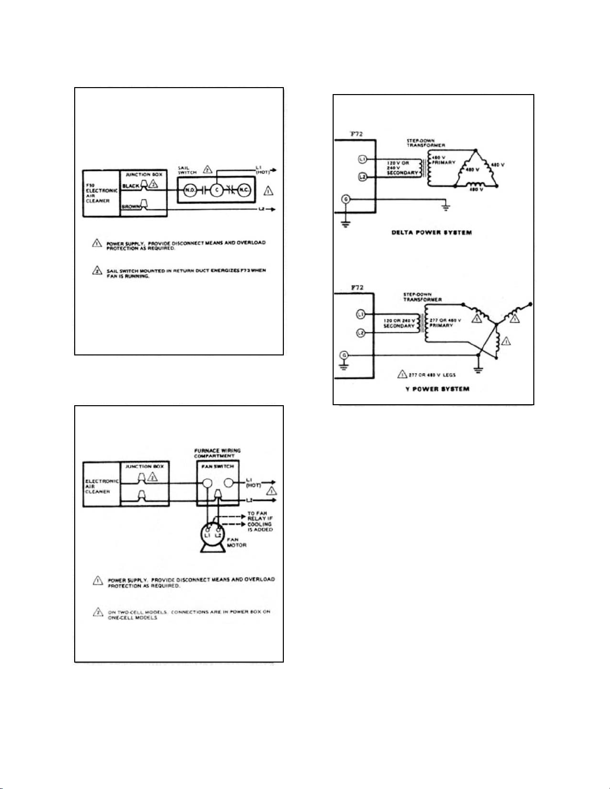
FIGURE 8 –MULTI-SPEED OR MODULATING
BLOWER MOTOR. (Air cleaner is controlled by
a sail switch.)
FIGURE 9 –SINGLE SPEED BLOWER MOTOR.
(Air cleaner is controlled by the fan switch
and/or the fan relay.)
FIGURE 10 –F72 AIR CLEANER HOOKUP TO
THREE PHASE, HIGH VOLTAGE POWER
SUPPLIES.

11
SERVICE
CLEANING THE ELECTRONIC AIR CLEANER
The F72 is used to remove a variety of
contaminants from the air. In the process of
cleaning the air, however, parts of the air cleaner
will become dirty and the cleaning efficiency will
be lowered.
In order to maintain a high standard of reliability
and efficiency, it is necessary for the F72 to
receive periodic maintenance. Periodic
maintenance means cleaning the collector cells
and inspecting the electronic air cleaner both
visibly and with instruments. Service will be
required if the air cleaner seems damaged or
appears to be performing at substandard
efficiency.
Air Quality Engineering, Inc., recommends regular
cleaning and the use of an alkaline detergent
solution. The exact scheduling is a matter of
experience since each air cleaning situation
varies. Actual experience may dictate a greater or
lesser period between cleanings.
If, because of excessive buildup of captured
contaminants, the alkaline detergent solution
proves inadequate, the use of physical force (such
as high-pressure air, water or steam) or an acid
detergent solution may be required.
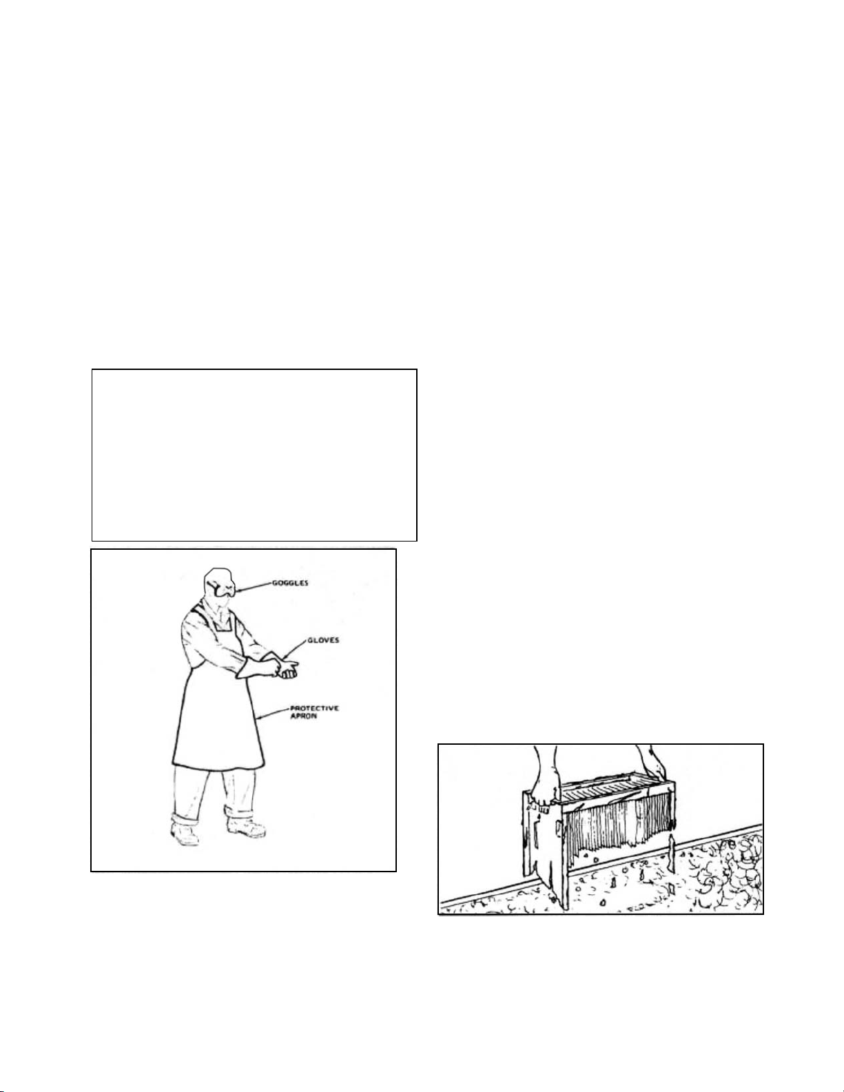
- CAUTION -
1. Be extremely careful when working with the
F72 cells and filters. The edges of the cells,
the filters, the collection plates and the ionizing
wires of the cells may be sharp.
2. When cleaning the cells and filters, be sure to
wear appropriate protective gear, especially
goggles and gloves. Skin contact with either
alkaline or acid detergent solution should be
avoided.
REMOVING THE ELECTRONIC CELLS AND
PREFILTERS
Before the electronic cells and prefilters can be
cleaned, they must be removed from the F72. Be
careful NOT to place a ladder or other heavy item
against the F72 unit, cells or prefilters. Electronic
air cleaners and their components are susceptible
to damage.
CLEANING THE PREFILTERS
The prefilters on an F72 do require cleaning. The
procedure is simple. Remove the prefilter and
shake the accumulated contaminants from it. If
this does not seem adequate, a vacuum can be
used; or the prefilter can be soaked in the alkaline
detergent solution. Do NOT soak the prefilter in
an acid detergent solution. Physical force
methods could also harm the prefilters.
THE ALKALINE DETERGENT SOLUTION
CLEANING METHOD
1. Provide a container large enough to hold the
electronic cells and prefilters to be cleaned.
2. Fill the container with detergent and hot water
sufficient to cover the electronic cell.
NOTE: Be careful to avoid prolonged skin
contact with the solution. Do NOT splash
solution in your eyes.
3. Soak the cells and prefilters in the solution for
about 15 minutes. The solution should be
agitated in some way, such as sloshing the
cells or prefilters or stirring the solution.
FIGURE 11 –WHEN SOAKING THE CELL,
AGITATE THE WATER.
4. Remove the cells and prefilters from the
alkaline cleaning solution and place them in
another container of hot water (150°F to 170°F
[66°C to 77°C] for rinsing. The cells and
prefilters should be rinsed for 5 to 10 minutes.
12
5. Remove the cells and prefilters from the rinse
water. Allow the cells and prefilters to drain
and dry before energizing them.
The collection plates of the electronic cells MUST
be checked for any detergent residue. If there is
any residue remaining, rinse if off since it may
affect the efficiency of the electronic air cleaner.
THE ACID DETERGENT METHOD
Air Quality Engineering, Inc., does sell an acid
detergent. However, acid cleaners should be
used only after alkaline detergents have proven to
be corrosive. They will decrease the life of cells.
If an acid detergent solution is used, be sure to
use a weak mixture. Do NOT place prefilters in an
acid detergent solution.
- IMPORTANT –
Acid cleaners must be properly handled. Refer to
the label on the acid detergent used. This means
wearing protective clothing, rubber gloves and
goggles, and reading all precautions on the label
of the detergent used. If contact is made in the
eyes, flush with a large amount of water and
consult a physician.
FIGURE 12 –BE SURE TO WEAR THE
PROPER EQUIPMENT FOR WORKING WITH
DETERGENT SOLUTIONS
NOTE: Be sure to provide adequate ventilation
when using acid detergents.
After the cleaning process is completed, the soak
water must be neutralized according to the U. S.
Environmental Protection Agency and state and
local pollution control guidelines and requirements.
Soda ash is one neutralizer.
1. Use a polyethylene or Type 316 stainless steel
container large enough to hold the electronic
cell. Other types of containers should be
avoided since the acid detergent may react
with the container material.
2. Following the instructions for temperature of
the water and amount of acid detergent used,
prepare the cleaning solution. The amount of
detergent and the soaking time will be
determined by the amount of contaminants
captured by the cells and the difficulty
encountered in removing the buildup. The
usual mix for acid solution is 2 oz. of acid
detergent to 1 gal. of water (59.2 ML to 3.8 L).
NOTE: It is recommended that acid cleaning of
any electronic air cleaner cells containing
metal oxide contaminants be performed with
room temperature or cold water. NEVER add
acid detergent to hot water.
3. Be sure to observe the cleaning operation
when the cells are placed in the acid detergent
solution. The amount of acid detergent should
be reduced if less than 30 seconds pass
before large amounts of bubbles are released.
The cells should NOT remain in the acid
detergent solution more than 30 seconds after
a vigorous reaction begins. It is a good idea to
remove the cells and inspect the cleaning
action of the acid detergent solution. If
contaminant deposits remain, the cells can be
returned to the solution.
FIGURE 13 –TOO MUCH TIME IN THE ACID
SOLUTION MAY HARM THE ELECTRONIC
CELL.
13
- IMPORTANT –
After the contaminants are removed by the acid
detergent solution, any further time the cells
remain in the solution serves only to decrease
their life.
4. After removing the cells from the acid
detergent solution, rinse them thoroughly for at
least five minutes.
5. Allow the cells to drain and dry before
energizing them.
STAINING
Occasionally after the soaking process, the cells
or prefilter may seem stained. If the stain is black
or very dark, it is probably detergent residue and
should be rinsed off at once. Detergent residue
may affect the electronic air cleaner’s efficiency.
If yellowing appears, it is probably staining. The
acid detergent solution will remove the yellowing.
However, it should be noted that the yellowing
does not affect air cleaner efficiency.
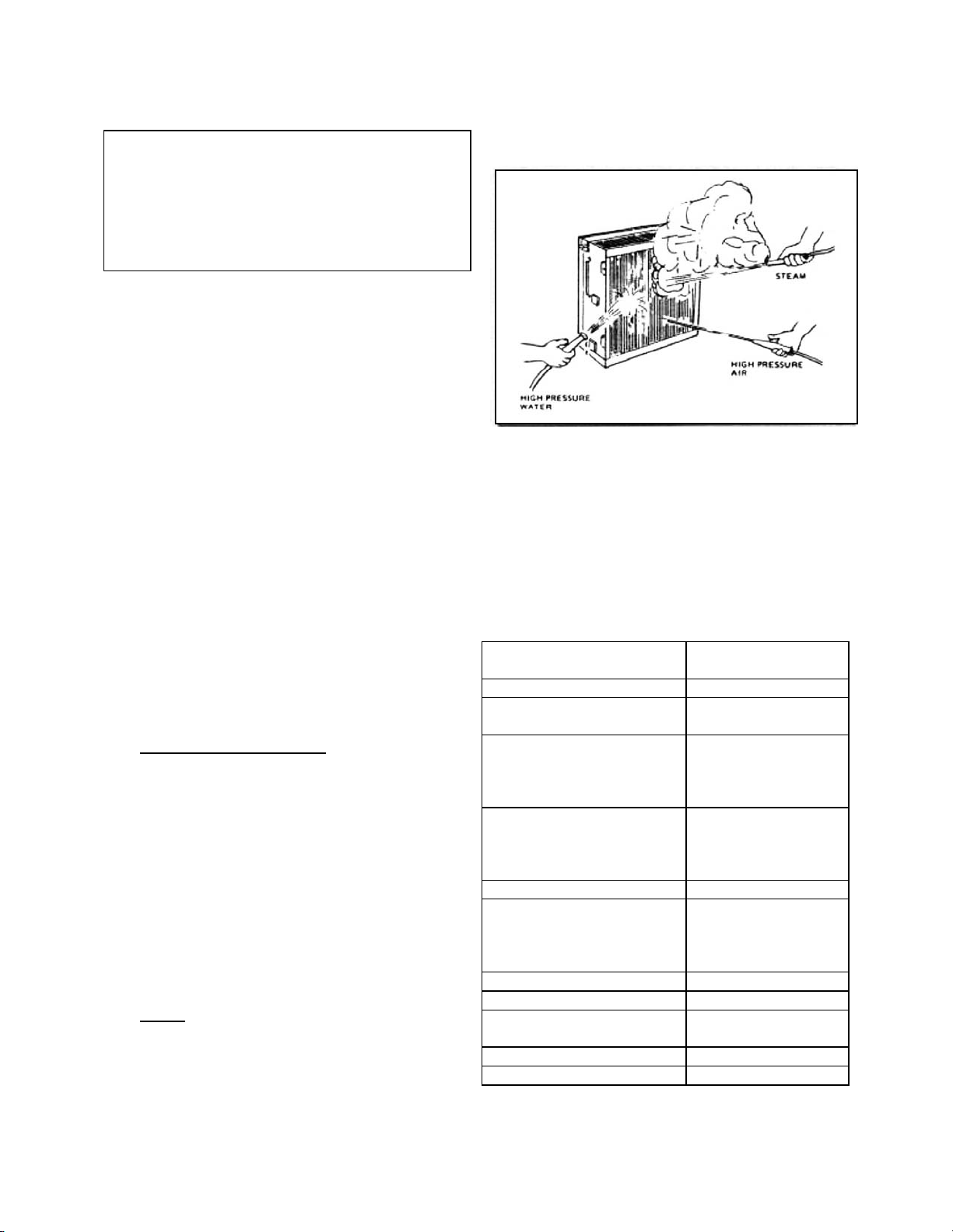
PHYSICAL FORCE METHODS
The following physical force methods may be
needed to clean some contaminants from the F72
cells. DO NOT use physical force methods on the
filter screens.
1. High Pressure Air or Water
Either of these methods should prove to be
adequate. However, care should be taken to
avoid damage to the electronic cells.
NOTE: Using any caustic detergent with high
pressure is dangerous.
If a detergent is required with the high-pressure
water, an alkaline detergent should be used if
allowed by the high-pressure equipment
manufacturer. DO NOT use an acid detergent
except when allowed by the equipment
manufacturer.
2. Steam
Extreme care must be exercised when steam
cleaning to avoid warping or bending the collector
plates of the electronic cells or any other damage
to the cells. Remember that the cells will be hot
after steam cleaning and that care must be taken
to avoid burns.
FIGURE 14 –IT MAY BE NECESSARY TO USE
PHYSICAL FORCE METHODS TO REMOVE
COLLECTED CONTAMINATION.
CONTAMINANTS AND CLEANING
PROCEDURES
The following is a selective listing of contaminants
captured by electronic air cleaners. This listing
gives the appropriate cleaning procedure for
various types of contaminants found on electronic
air cleaner collector plates and prefilters.
CONTAMINANT
CLEANING
PROCEDUREª
Animal Hair
Alkaline Solution
Cabosil
Alkaline Solution
High Pressure Air
Carbon –
(carbon black, soot, lamp
black, graphite, charcoal,
dust,etc.)
Alkaline Solution
High Pressure Air
High Pressure Water
Cooking Oils –
Veg. (soybean, peanut,
etc.)
Animal (lard, butter, etc.)
Alkaline Solution
Steam
Cotton Fibers
Alkaline Solution
Dust –
(silicon dioxide, calcium
carbonate and mineral
type compounds)
Alkaline Solution
Flour Dust
Alkaline Solution
Linseed Oil
Alkaline Solution
Lubricants
Alkaline Solution
High Pressure Water
Metal Oxides
Acid Solution
Metals
Acid Solution
14
CONTAMINANT
CLEANING
PROCEDUREª
Mineral Oil –
(petroleum base, diesters
and silicone)
Alkaline Solution
High Pressure Water
Paper Products
Alkaline Solution
Paint –
Oil Base, Water Base
Alkaline Solution
Pine Tar Resins
Alkaline Solution
Steam
Polyethylene
Alkaline Solution
Polyphenyleneoxide
Alkaline Solution
Polypropylene
Alkaline Solution
Rubber Molding
Accelerators
Alkaline Solution
Soaps
Alkaline Solution
Sodium Chloride
Alkaline Solution
Sugar –
(includes molasses)
Alkaline Solution
Steam
Talc
High Pressure Air
Alkaline Solution
Tobacco Tars and Smoke
Alkaline Solution
Varnishes
Alkaline Solution
Waxes –
(all types)
Alkaline Solution
Steam
Welding Fumes
Acid Solution
Wood Products
Alkaline Solution
ªCleaning procedures are listed in order of preference.
REPLACING THE CELLS
Before replacing the electronic cells, be sure to
visually check the electronic cells for bent or
damaged collector plates or broken ionizing wires.
Bent or warped collector plates may be bent back
into shape.
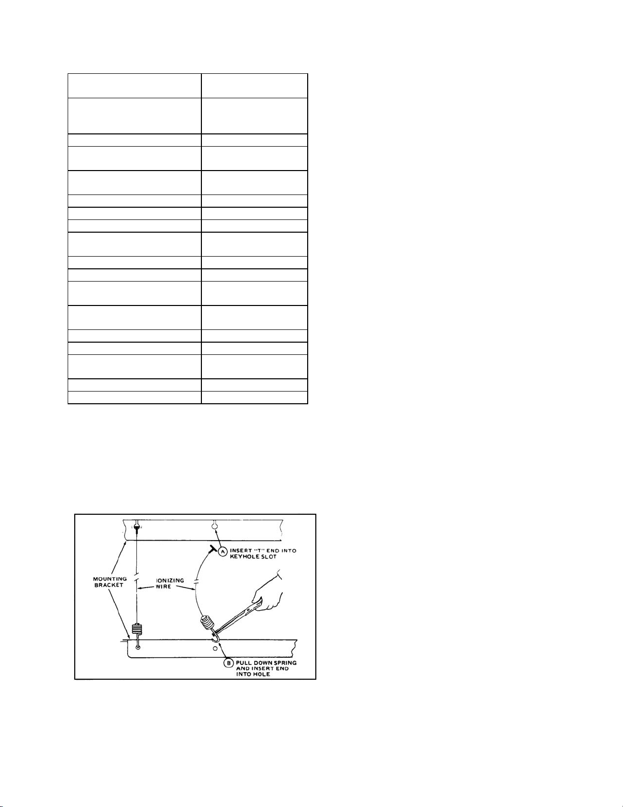
FIGURE 15 –REPLACING IONIZING WIRES
Broken or damaged ionizing wires must be
replaced for top efficiency. Remove all parts of
the broken or damaged wire. Replacement wires
come cut to length and ready for installation.
Remember that wires come cut to length and
ready for installation. Remember when replacing
the ionizing wires to:
1. Use care to avoid damage to the spring
connector or other parts of the cell during
installation.
2. Hook “T” end of the ionizing wire in the
keyhole slot at one end of the cell.
3. Pull down the spring with a needle-nose pliers
and insert hook into the hole.
Before replacing the cell, it might be a good idea
to check it for a short circuit. This is done by using
an ohmmeter to check the resistance between the
frame of the cell and both the ionizer and collector
contacts. In each case, the resistance should be
infinite.

15
TROUBLESHOOTING
- CAUTION -
1. During troubleshooting, dangerous line voltage
circuits are exposed. Use extreme care to
avoid electrical shock or equipment damage.
2. Although not normally lethal, the high voltage
output of the electronic air cleaner power
supply can produce a painful shock. Use
caution.
TROUBLESHOOTING PROCEDURE
The following procedure has been designed to
speed troubleshooting and to insure the quick
detection and proper repair of any malfunction in
the electronic air cleaner.
Most of the troubleshooting steps can be
performed by observing the performance indicator
light and by pushing the test button.
Troubleshooting can be done with only a few tools:
xTest Meter –Simpson 248 Hi Voltage meter or
equivalent.
xNeon test lamp for line voltage.
xScrewdrivers –long shank with plastic or
rubber handles.
xNeedle nose or long nose pliers –for replacing
ionizing wires.
FIGURE 16 –F72 TROUBLESHOOTING FLOW CHART
16
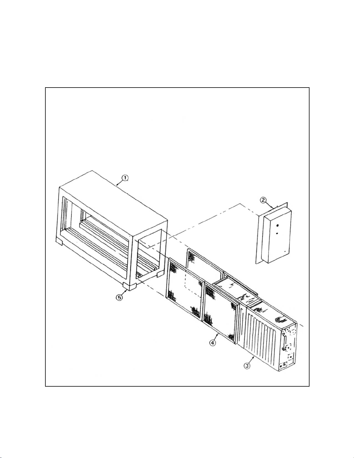
FIGURE 17 –EXPLODED VIEW OF THE F72 ELECTRONIC AIR CLEANER.
17
PARTS LIST
NO.
DESCRIPTION
PART NO.
F72A
F72B
1
Cabinet Assembly
05413
05416
2
Door, 120V
05414
05414
3
Door, 240V
05415
05415
4
Electronic Cell(s)-F72A (1), F72B (2)
38010
38010
5
Pre/Post Filters-F72A (2), F72B (4)
41113
41113
6
Cabinet Foot
21411
21411
7
Ionizer Wires
38005
38005
8
Indicator Light
10097
10097
9
High Voltage Power Supply Replacement Kit, 120V
07081
07081
10
High Voltage Power Supply Replacement Kit,
208-240V
07083
07083
11
Male Connector
46199
46199
12
Female Connector
46198
46198
13
Media Prefilter Frame
41111
41111
14
Media Prefilter Pad
41112
41112

18
NOTES:
___________________________________________________________________________________
___________________________________________________________________________________
___________________________________________________________________________________
___________________________________________________________________________________
___________________________________________________________________________________
___________________________________________________________________________________
___________________________________________________________________________________
___________________________________________________________________________________
___________________________________________________________________________________

19
NOTES:
___________________________________________________________________________________
___________________________________________________________________________________
___________________________________________________________________________________
___________________________________________________________________________________
___________________________________________________________________________________
___________________________________________________________________________________
___________________________________________________________________________________
___________________________________________________________________________________
___________________________________________________________________________________

20
CERTIFICATE OF WARRANTY
ONE-YEAR LIMITED WARRANTY
Air Quality Engineering, Inc. (AQE), warrants the Smokemaster® Electronic Air Cleaner to be free from
defects in workmanship or materials, under normal use and service, for a period of one (1) year from the
date of purchase by the consumer. If at any time during the warranty period the product is defective or
malfunctions, AQE shall repair or replace it (at AQE’s option) within a reasonable period of time.
If the product is defective:
(i) obtain a Return Goods Authorization (RGA) Number from your AQE representative,
(ii) return the unit or defective component with a bill of sale or other dated proof of purchase to the
retailer from which you purchased it, or
(iii) package the unit or component along with proof of purchase (including date purchased) and a
short description of the malfunction, and mail or ship postage or freight prepaid to the following
address:
AIR QUALITY ENGINEERING, INC.
Warranty/Return Goods Department
7140 Northland Drive North
Minneapolis, Minnesota 55428-1520
The repaired or replaced part or unit will be shipped freight collect by AQE to the purchaser with the
purchaser to be responsible for all freight charges. The warranty on any repaired or replacement part
shall be for a duration of time no longer than the remaining or unexpired term of the original warranty.
This warranty does not cover any labor or other service charges incurred by the purchaser.
This warranty shall not apply if it is shown by AQE that the defect or malfunction was caused by damage
that occurred while the product was in the possession of the consumer.
AQE’s sole responsibility shall be to repair or replace the product within the terms stated above. AQE
SHALL NOT BE LIABLE FOR ANY CONSEQUENTIAL DAMAGES RESULTING FROM ANY BREACH
OF WARRANTY, EXPRESS OR IMPLIED, APPLICABLE TO THIS PRODUCT. Some states do not
allow the exclusion or limitation of consequential damages so this limitation may not apply to you.
THIS WARRANTY IS IN LIEU OF ALL OTHER WARRANTIES, EXPRESS OR IMPLIED, AND THE
WARRANTIES OF MERCHANTABILITY AND FITNESS FOR A PARTICULAR PURPOSE ARE HEREBY
EXCLUDED BEYOND THE ONE-YEAR DURATION OF THIS WARRANTY. Some states do not allow
limitations on how long an implied warranty lasts so the above limitation may not apply to you.
This warranty gives you specific legal rights and you may also have other rights that vary from state to
state.
AIR QUALITY ENGINEERING, INC. TOLL FREE: 1-800-328-0787
7140 NORTHLAND DRIVE NORTH TELEPHONE: (763) 531-9823
MINNEAPOLIS, MINNESOTA 55428-1520 FAX: (763) 531-9900
MANUFACTURER & WORLDWIDE DISTRIBUTOR OF SMOKEMASTER® AIR CLEANING SYSTEMS
PN 51587 Printed in the USA
This manual suits for next models
4
Table of contents
Other Smokemaster Air Cleaner manuals


