Smokemaster X-4OO Instruction Manual

@
NOWNER
AND
SERVICE
MANUAL
SMOKEMASTER'
MODEL
X-4OO
SELF-CONTAINED
ELECTRONIC
AIR
CLEANER

TABLE
OFCONTENTS
PAGE
OWNERSMANUAL
PART
I
INTRODUCTION
COMPONENTS.
PRINCIPLES
OFOPERATION
OPERATINGINSTRUCTIONS
MAINTENANCE
.
SERVICE
INSTALLATION
AND
SERVICE
PART
II
SPECIF|CATTONS ......5
GENERALINFORMATION.. 6
Application 6
Make-UpAir... 6
Sizing 6
INSTALLATION 7
GHECKOUT.... I
SERVICE 9
ELECTRICALTROUBLESHOOTING. .....10
DTAGNOSTTCCHECKS ......11
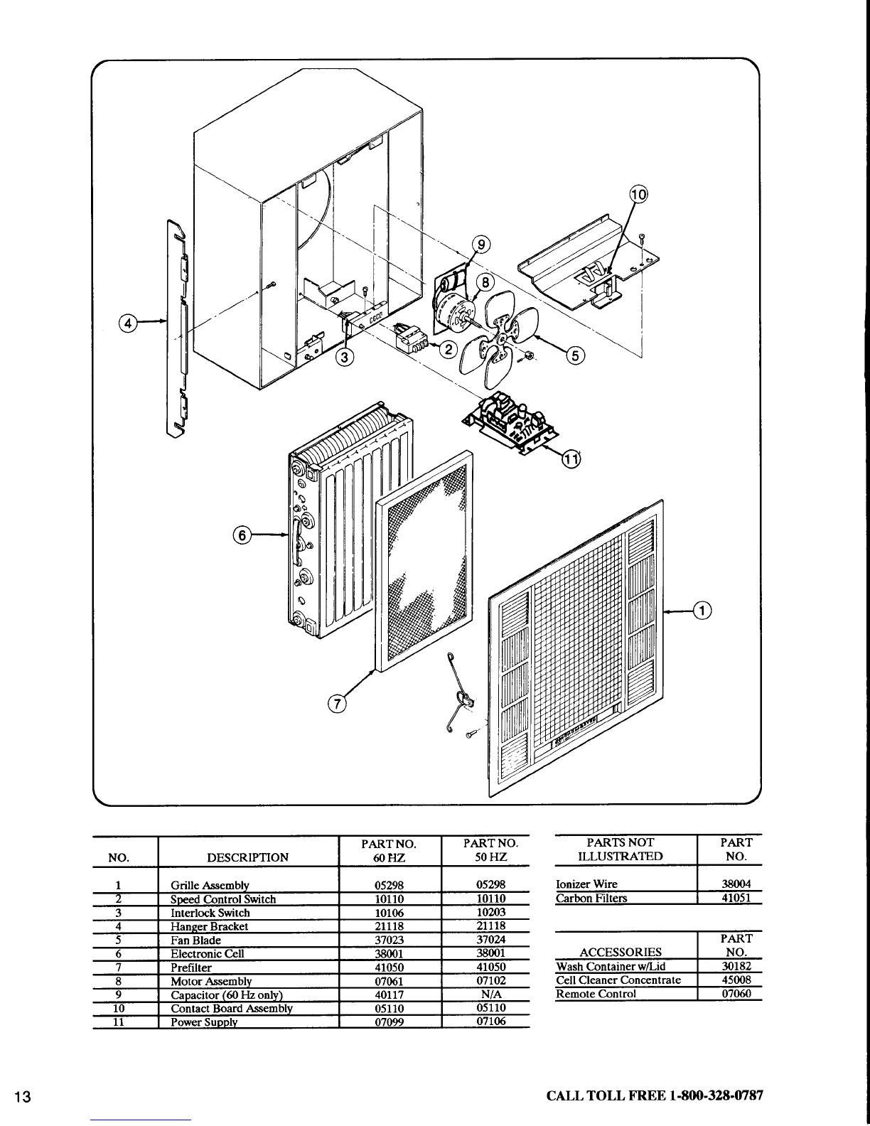
PARTSLIST. ....13
GUIDESPECIFICATIONS ....14
MADEWITHPRIDEINTHEU.S.A.

OWNER
MANUAL
SMOKEMASTER
PART
1
Your Smokemaster
X-400
is an advanced
self-contained
electronic
air cleaner.
ThemodelX-400
is an
efficient indoor pollution fighter while reducing costly energy consumption. It is designed to be
installed
in the space
of a 2 x 2 drop ceiling
panel.
CLEAN
AIR
A clean fresh atmosphere
is a plus to any business.
With your new Smokemaster
Electronic
Air
Cleaner,
your customers
and ernployees
cannow breathe
air that is relatively freeof smoke,
dust or
pollen.This is especially
important with regardto today'sconcern
with the effects
of smokersupon
non-smokers
and also
for a morecomfortable
environment
for allergy
sufferers.
LOWER
ENERGY
CONSUMPTION
A common
solutionto the problem
of dense
concentrations
of smokeis to exhaust.
Excessive
exhaust-
ing is wasteful and very expensive.
One is exhausting
expensively
heated
or cooled
air and needing
to heator coolthe outdoor air coming
in. A Smokemaster
X-400
drastically
reducesthe need
for out-
sideair. Thismeans
you can
saveas
muchas40percent
on heating
andcooling
bills.
REDECORATING
Smokeparticles also ha_ve
a tendency to settle out as a dulling film on mirrors, windows, trophies,
bottles
and glassware.
In fact, most of the particles
which prJiuct soiling and staining are lust too
smallto beremoved
by_average
dusting.Electronic
air cleaning
gets
rid of-theseparticles
before
they
have a chance
to start the soiling process.
Less
soiling meansioig"t periods betweenredecorating.If
the appearance
of your business
is important to you, electronic
air-cleaningis certainly a plus.
EXTRACOMFORT
AND SAVINGS
The
effective
air patternof the ModelX-400
creates
a morecomfortable
atmosphere
by constant
slight
air movement.
This slight movement
also
helpsto eliminate
existingdrafts. Another side benefiiof
the air recirculation
Pattern
is that it distributes
the heated
or cooled
air more evenly.
Thisevendis-
tribution helps
to reduce
the amountof heated
or cooled
air needed
for the samedegiee
of warmth or
cool.
LOWOPERATING
COST
In addition to reduced
heating/cooling
billsand redecorating
bills,the relativelylow cost
of maintain-
ing an X-400
electronic
air cleaner
is another
financialboostto your business,
this air cleaner
hasno
throwaway filter or other parts that must be periodically
replaced.
The durable electronic
cellsand
prefilter screens
are washedand used over and over again.No replacement
parts meansreduced
maintenance
cost.
2

COMPONENTS
COMPONENTS
OF
THEX.4OO
ELECTRONIC
AIR CLEANER
Cabinet
The sturdy corrosion resistant steel cabinet
requires only 13-9116" spaceabove drop ceiling
for installation.
Mounting System
Speciallydesigned support bars simplify installa-
tion - makes mounting of air cleaner safe and
Becureevenduring installation.
Power
Supply
Solid state power supply assures trouble-free,
highly reliableservice.
Grille
Attractive one-piece grille conveniently drops
down. All serviceable components are accessible
through the grille opening.
ElectronicCelle
One electronic cell charges and collects airborne
particles. The compact design allows easyremoval
for cleaningand service.
FanMotor
Motor driven fan operates at 3 speedsproviding
the choiceof circulation level. Elastomeric
suspen-
sion systemeliminatesvibration noise.
Capacitor
PRINCIPLES
OFOPERATION
HOWYOURELECTRONIC
AIR CLEANERWORKS
,irbornc contaminants arc trappcd bv a process
callcd
ElcctrostaticPrccioitation." Thc fan-draivs particulatc
rden
airsucccssivcli
throughthcprcfilter,thccill ionizing
Airbornc contaminants arc trappcd bv a proccss
callcd
"Elccrostatic Prccipit-ation.:' Th" fa.n-
draivs p-articulatc
ladenair succcssivcli
throush thcprcfilter.thccill ionizins
section and ccll c6llcctor-scctioh. Thc ionizinc sectionrzlng seoron
section and ccll c<i
Collcain3
Sccrion
L---__1///
Ctcen
Air
Our
+
il]|q;i';;-"i;;i.i;ili;.s;-i;'ii,eildilfti'-J"piiiiii.irmDarts an clcctncal charlc to tnc lnclvldual par
which arc thcn drawn by cfcarostatic forccs to th.c <
sitcly charged .collcctor pl:
discharsedSackinto thcroom.
srtclY cna
discharged
.ncal chartc to tnc rnctvldual D
,rawn
bv cfcctrostaticforccs
to th,
collcao'r platcs. Clcaned air i
lc op.po-
rs thcn
Electronicccllsmust
bc washed
pcriodically
to maintain
cff
icicnt
pcrform
ancc.
3
Cherging
Scclion \_
r--!\:
------n4....
Dirty :. ... .
Air .---\.:..
In '--t4
','...
F--:-J\. .
L=.4

OPERATING
INSTRUCTIONS
SAFETY
INTERLOCKSYSTEM
In order for all air cleaner functions to receive
operating power the grille must besecurelyin posi-
tion. This actuatesthe safety inter-lock switch. Air
cleanerwill not function without grille in place.
FANSWITCH
Your electronic air cleanerhas an Off-Low-Med-Hi
switch. The electroniccollectionsystemand built-in
fan are designed to run simultaneously. Turn off
the air cleanerbeforedropping the grille to remove
the electronic
cellsfor cleaning.
SYSTEMLIGHT
Your electronic air cleaner is equipped to tell you
simply and quickly that it is working properly. The
amber system light tells you at a glancethe status
of the power supply. The systemlight should beon
when the unit is on.
TEST
BUTTON
Pushing the white button labeled "push to test"
generates
a snapping noise which indicates proper
function of collectorsystem.
MAINTENANCE
WASHING
THEELECTRONIC
CELL AND PREFILTER
To maintain peak efficiency, the electronic cells
and prefilter in your electronic air cleaner must
bewashed regularly. The washing is necessary
to
remove dirt particles collected from the air.
Check with your Air Quality Engineering
representativeto determine how often your cells
needto bewashedfor your particular application.
Grille may be removed from machine for periodic
washing. CAUTION
1. Beextremelycareful when working with X400
cell and filter. The edgesof the celle
and filter,
and the collection platee and ionizing wlreo of
the cell may be eharp.
2. When cleaningthe cellsand filtere, besureto
wear rppropriete protective geat, espectallygog-
gleeand glovee. Skin contactwith either alka-
line or acid detergent solution should be
avoided.
3. Usea etable
platform to etandon when work-
ing wlth the electronic air cleaner.
4. Electronic air cleaners and their components
aresuoceptibleto damage.Teke carewhen work-
ing wlth them to avoid equipment
damage.
1. Fill wash tub with cell cleaningdetergentand
hot water per detergent manufacturer's instruc-
tions.
2. Immerse cells in CLEANER and remove immedi-
ately.
3. Remove cells and set aside for five minutes to
allow CLEANERto penetrate.
4. Rinsecells well with hot water. Make certain no
residue remains on cells. Residue will adversely
affect cell performance by causing frequent arcing
and low efficiency.
.5. Inspect cells for broken wires or bent plates.
Repair or replaceas necessary.
(See
ServiceSection
for ionizer wire replacement
procedure.)
5. Removelint from prefilter with vacuum cleaner
or wash with mild detergent solution.

SERVICE
In the event of air cleaner malfunction there are
somesimple checks
you canperform to determine
if a serviceman
mugt becalled.
1. Checkcircuit fuse or breaker.Correct if fuse is
blown or breakeris tripped.
2. Be sure electronic cell is in place,intake grille
is closed
and unit is turned on.
If the problem persists, call serviceman.
The fol-
lowing information will beuseful to him.
1. Whether or not ambersystemlight is on.
2. If pushing white test button results in a snap-
ping sound.
ARCING
Frorr time to time you may hear a snapping noise
coming from the electronic air cleaner.This arcing
occurs when the air cleaner collects an unusually
large particle, when cell is wet, extraordinarily
dirty or damaged.
If an unusual amount of arcing persists,check
first
to determine if the electronic cell needs washing.
Look also for any sign of bent collector plates or
brokenionizer wires.
If arcing still occurs when cell is clean and dry,
consult your serviceman
or dealerfor repair.
INSTALLATION
ANDSERIIICE
SMOKEMASTER
PART
2
SPECIFICATIONS
Model X-400includes
oneelectronic
celland
a3-
speed
fan. Discharges
air in up to four directions
parallelto ceilinguponwhichit ismounted.
CAPACITY:
ELECTRICAL RATINGS:
Voltage
andFrequency
- l2OYac,6OHz;
220240Vac,50
Hz
CURRENT
AND POWBRCONSUMPTION:
EFFICIENCY: Up to 97percent
efficiency
is
delivered
asmeasured
according
to theNBSDust
Spot
Method
usingatmospheric
dust
as
outlined
in
theAmerican
Society
of Heating,
Refrigeration
and
Air Conditioning
Engineers
(ASHRAE) Srandard
52-76.
WEIGHT: 54lbs.(25
kg)shipping,44lbs.
(20
kg)
installed,
including
electronic
cells.Each
cellweighs
91,2tbs.(a3 kg).
AMBIENT TEMPERATURE
RATING:
Shipping
andStorage:
-40
to +150
degrees
F.
Operating:+40to *125 degrees
F.
UNDERWRITERS
I,ABORATORIES
INC.,
LISTED:
FileNo.855711,
Guide
No.AGGZ
(ffiHz models
only)
CANADIANSTANDARDS
LISTED:
FileNo.
LR89416-1
DIMENSIONS:24"
x24'x 13518"

GENERALINFORMATION
APPLICATION
TheX-400
ismounted
intheroom
orarea
where
theairistobecleaned.
Onevery
common
appli-
cationisthe
removal
oftobacco
smokefrom
the
air.Typicalinstallations
include
conference
rooms,
lounges,
offices,
lunchrooms,
etc.
Because
itprovides
itsown
circulation,
the
X-400
maybeused
inalmost
any
applicationrequiring
theremoval
ofairborne
particulate
contamination
from
anenclosed
space.
WARN
The
X-400Electronic
AirCleaner
isnot
explosion
proof.
ltmustnot
beinstalled
where
there
isdanger
of
vapo/,
qas,
ordust
MAKE.UP
AIR
Recommended
quantities
ofcleanoutdoor
ventlla-
tion
airfor
various
applications
are
described
in
Table2ofthe
ASHRAE
Standard
62-89
.Ventilation
forAcceptable
Indoor
Air
Quality.'ASHRAE
(American
Society
of
Heating,
Refrigerating,
and
Air
Gonditioning
Engineers,
Inc.,Phone
#404-636-
8400)notes
that
these
recommended
outdoor
air
quantities
maybereduced
bytheuse
ofclean,
recirculated
airifthe
IAQProcedure
6.2is
used.
Appendix
EofASHME62-89
includes
recom-
mendations
fortheuseofclean
recirculated
air.
However,
inmost
cases,
adequate
control
ofcar-
bondioxide
generally
requires
aminimum
clean
outdoor
air
quantity
ofno
lessthan
15cubic
feetof
air
per
minute
per
person.
Additional
ventilation
maybe
requiredfor
toxic
con-
taminants.
Inany
event,
theaircleaner
must
be
used
onlyin
areas
which
areventilated
for
human
occupancy
inorder
todisipate
anyincidental
gen-
eration
ofozone.
stzrNG
Electronic
aircleaners
are
generally
best
sized
according
tothe
use
ofthearea
andthe
volume
of
theroom
(Air
Changes
per
Hour
Method).
Secondary
factors
toconsider
inapplying
elec-
tronic
air
cleaners
include:
-type
ofcontamination
-number
ofoccupants
-orrtside
airquality
-anticipated
fansetting
-rate
ofcontaminate
generation
By
considering
these
factors,
thenumber
ofair
cleanersrequired
can
beadjustedupordown
to
account
forabnormalities
in
operatingconditions.
Follow
Steps1through
4below
todetermine
the
numberof
aircleaners
required:
Steo1
-Measurethelength,rividth,
andheight
oftheroomin
feet.
Step
2-Determine
theAirChanges
per
Hour
required.
See
ChartAbelow.
Step
3-Determine
theC.F.M.
(Cubic
Feet
per
Minute
ofAir).See
ChartBbelow.
Step
4-Plugthefigures
from
Steps1-3
intothe
sizingformula
below
andcalculate
thenumber
of
aircleaners
required.
SIZING
FORMULA
LxWx Hof Room
xAirChanges
/ Hr.
= # ofX400's
C.F.M.of
Air
(see
Chart
B)x60Min.
NOTE:
The
maintenance
interval
for
cellcleaning
canbe
lengthened
byincreasing
thenumber
of
aircleaners
beyond
therequired
number.
CHART
A. AIRCHANGES
PERHOUR
Load Descrlptlon
of
Appllcatlon AlrChanges
Per
Hour
Llght Generaloffices
&
computer
rooms 4-5
Average Conference
and
break
rooms 6
Heavy Designated
smoking
areas,
bingohalls,
bars,
&elilra
smoky
areas.
8-10
CHART
B. CUBIC
FEET
OFAIRPER
MINUTE
The
aircleaner
has
athree-speed
fan
motor.
Usethe
C.F.M.that
corresponds
tothespeed
that
theair
cleanerwill
operate
onnormally.
Low
speedwhere
noise
isaprime
concern
and
high
speed
wherenoise
isnot
afactor.
ModelX400 Low Medlum Hlgh
c.F.M. 175 275 400
Nolse
Level 45
dB(A) 50.5
dB(A) 56.5
dB(A)

INSTALLATION
IMPORTANTI Read theeeinstructions carefully.
A hazardous condltion or damage to product
could result lf lnstructions are not followed.
CAUTION
1. Do not connect power source until after the
electronic alr cleaner ia nounted. Electrical
ehockand equipment danage may result.
2. Be eure to turn air cleaneroff prior to service
or inetallatlon. Motor has automatic thermal
overloadeolt will stop when overheated.It will
automatically
start after a coollng
period.
3. Avold electrlcal ehock by being careful when
air cleaner le turned on for electrical check.
Aleo, be careful when working nearair cleaner's
moving parts.
4. Weargloves
when lnstalling air cleanerto pro-
tect handsfrom cuts.
EQUIPMENT
NEEDED
1. Phillips screwdriver
2. Wire cutters
3. Pliers
4. Knife
5.Hacksaw
5.Electric
drill (with 1/8" bit)
7. Wire Pliers
8. Four 1/4 inch turnbuckles from your local
hardware
store.
9. Twelve gaugegalvanized steelwire (enough to
hang four wires from true ceiling to T-bar level).
10. Enough twelve or fourteen gauge electrical
wire and conduit to reachnearestunswitched cir-
cuit (see
electricalinstallation instructions).
11.Junctionbox fittings asneeded.
ITEMSSUPPLIEDASLOOSEPARTS
1. Two support bars
2. Six #8 self-tapping sheetmetal screws
3. Two flat washers
4. Two wire connectors
UNPACKING
Note: It is easierto leave air cleanerin box until
Step
5.
1. Remove grille and unpack from protective
cardboard.
2. Takeout prefilter
3. Remove
electroniccell by turning the retaining
turnstile latch. Then raisecell off hooks.
4. Removemounting barsfrom inside of cabinet.
5. Lift air cleaner
out of box.
PREPARATION
The model X-400 air cleaner is designed to be
installed within a T-bar drop ceiling. Removetiles
from ceiling to open an area23 inches (one 2' x 2'
ceiling tile) to accommodateair cleaner.The area
between the drop ceiling and true ceiling must be
free of obstructionssuchaspipes,ducts, etc.There
must be at least 14 inches between the bottom of
the T-barand true ceiling.
Make sure air cleaner will be oriented and located
for good air circulation.
MOUNTING
WARNING
Air cleanercould fall from celling if improperly
mounted. Installation lnstructions must be fol-
lowedcatefully to avoid iniury to people
anddam-
ageto equipment.
1. Attach f.our72 gaugegalvanizedsteel suppoft
wires to true ceiling at location shown in Fig. 1.
Twist eachwire at least four times to provide safe
support for the air cleaner, The free end of each
wire should extend six inches or more below the
bottom of the T-bars.
tu
Turnbuckles
FIGURE1
2. At the end of each opening, set a support bar
acrossthe T-bars. The "1" shaped portion of the
support barsshould beoriented sothe hook sideof
the "1" is toward the opening (not toward the
adjacent
T-bars).SeeFig.1.
3. Using an electric drill with and 1/8" drill bit,
drill through the holes in the stepped portion of
the support bars and through the T-bars. Attach
the support bars to the T-barswith four #8 sheet
metal screws
provided.

4. Hook the turnbuckles to the support bars and
then securethe support wires to the eyesof the
turnbuckles (see Fig. 1). Twist the wire at least
four times.
5. Adjust the turnbuckles until the support bars
are securelysuspended
by the support wires. Do
not overtighten the turnbuckles to avoid lifting
or buckling the T-barframework.
6. Lill air cleanerbody into opening and let body
drop into Jshapedportion of support bars.
7. Fasten
air cleaner
body to support barsusing
two #8 self-tapping screws and flat washerg.
Screws
are installed through slotsin endsof air
cleaner
into support bars. Adjust location
of air
cleaner
relativeto support barsvia slotsprior to
tightening of screws.
ELECTRICALINSTALLATION
CAUTION
This ptocedure
should beattempted
only by per-
sons qualified to install electrical wiring. All
wiring must comply with applicablecodes
and
ordinances.
1. Locate an unswitched 120 volt AC, 60 }Jz.
power circuit with a junction box near the air
cleaner
location.
2. Check the circuit breaker or fuse for that cir-
cuit and determine
whetherit is rated15amperes
or 20 amperes(as marked on the device).
The
required copperwire sizewill be:
AWG #14 for 15ampere
circuits.
AWG #12 fot 20
amperecircuits.
3. CAUTION: Turn off the building circuit at the
fuse
or circuit breaker
before
proceeding.
4. Connect the black and white wires from the
pigtails in the air cleaner junction box to the
corresponding
colorsin the supply circuit (Fig.2).
Blackfrom
AirCleaner
5. If grounded conduit is used to route the power
wiring to the air cleaner, no further grounding is
neceseary.
[n the absence
of a grounded conduit
connection,the green wire in the field wiring com-
partment should be connectedto a grounded con-
ductor. DO NOT connect the grounding wire from
the air cleaner to the white wire or the building.
The air cleaner frame must be electrically con-
nectedto the frame of the building of the electrical
conduit system. Input electrical power should be
run through flexible conduit as recommended by
the National Electrical Code or your local author-
ity.
COMPLETING
THEASSEMBLY
1. Install electronic
cell.
2. Checkto makesure the electroniccell is oriented
for correct airflow. arrows on side of cell should
point up. The contact board needs to be properly
seated.
3. Install the prefilter.
4. Install the grille by squeezingtwo of the mount-
ing springs locatedalong one side of the grille and
inserting the "legs" of the springs into the slots in
the mounting bars.Besure the grille is oriented so
it will swing up and cover the air cleanercorrectly.
Swing the grille up and attach the remaining two
springs to the other mounting bar. At this point,
simply push the grille toward the air cleaner and
the springs will pull the grille up into its final posi-
tion.
5. Turn electricpower backon and pressHI, MED,
LO button.
6. Make sure fan runs on all three speedsettings.
7. Presstest button. An audible snap indicatescol-
lection sectionof cell is functioning.
8.Cleanup installation
area.
8
=N
FIGURE
2

CHECKOUT
Before leaving installation, be sure the X-400 is
properly installed and operates correctly. Check
the following:
MOUNTING
eThe X-400 is securely fastened to the true ceil-
ing.
ASSEMBLY
.Electronic cell is correctly oriented-airflow
arrowspointing toward blower.
oPrefilterscreenproperlyinstalled.
OPERATION
.Fan runs correctly on all speedsettings.
oSystemlight turns on when fan is running.
.Snapping noise is heard when test button is
pushed.
.Opening intake grille stops fan and turns out sys-
temlight.
NOTE: If the X-400 does not appear to work right,
refer to ELECTRICAL
TROUBLESHOOTING.
CLEANUP
.Clean the surfaces
of the air cleaner.
.Clean up the installation
area.
SERVICE
WARNINGI
The following instructionsarelntended for qual-
ified service
personnel
only. Dangerous
line vol-
tage circuits are exposed
during this procedure.
Dieconnect
powerat fuee
before
servicingunit.
MOTOR
REPLACEMENT
PROCEDURE
1..Disconnect
powerat fuse
or circuitbreaker.
2. Open grille. Remove prefilter and cell to pro-
videaccess
to motor.
3.Remove
fan blade
from motor.
4. Disconnect
fan motor leadsat plug disconnect
near
electrical
compartment.
5. Remove 5 screws holding motor to unit to
remove
motor.
5. Install new motor, connect
electrical
lines and
replace
fan, cell, prefilter and grille.
7. Connectpower and check
new motor operation.
PO\ilER SUPPLY REPLACEMENT
PROCEDURE
1.Disconnect
powerat fuse
or circuit breaker.
2. Open service grille and remove prefilter and
cell.
3. Remove six Phillips head screws holding the
electrical cover in place.Disconnect the two high
voltage wires from the back of the cell contact
boardassembly
and lay the electrical
coveraside.
4.Disconnect:
1. White wire from power supply.
2. BlackWire from power supply.
3. Charcoaland pink high voltagewires (one
each)
at power supply.
5. Cut wire ties holding the above wires to the air
cleaner.
5. Remove4 screwsholding power supply in place
and removepower supply.
7. Mount new power supply in placereconnect
wir-
ing.
8.Use
wire tiesand re-tiewiresin place.
9. Reconnect
the high voltage wires and reinstall
the electricalcover.
10.Replace
the electronic
celland prefilter.
11.
Closeservicegrille.
12. Reconnect
power and test power supply with
test button to besure unit is operating properly.

IONIZINGWIRE REPLACEMENT
The fine tungsten ionizing wires in the charging
sectionof th; electroniccell may break or hcome
damaeed.
Inspect
the cellfrom ihe upstream
side
after "washini to make sure that irone of the
wires arebroFenor out of position. During oPera-
tion, a broken or deformed wir-e
generally causes
a short to qround, possibly with visible arcing or
sparkins. This conilition,-or any other short in
tfre ionlzins section of the celf, will cause the
indicator lig"ht
to to out.
Broken wires must be replaced for air cleanerto
function effectivelv withbut arcing. Remove all
parts of the broktin wire. If nece-ssary,
the cell
inav be temporarily used with one wire missing.
See'PARTS
LIST trir part number of replacement
wire. Wires come cdt to length with -eyelets
at
each end for easy installatioir in the electronic
cell.
1. Use care to avoid damage to the spring conn-ec-
tor or other parts of the cell during the instaua-
tion.
2. Hook one end of the ionizing wite over the
spring connector
at oneend of the cell.
3. Hold the opposite eyelet with a needlenose
pii"ti ""a stret'chthe wiie the length of the cell'
b;t;"s, the opposite spring conneltor and hook
the eyeletover it.
MOTORMAINTENANCE PROCEDURE
The rnanufactuter of the motor used in the X-400
recommends oiling of the motor at least once a
year. The followinlg procedurecanbefollowed:
*De-energize
the unit.
*Remove
the prefilter and cellsfrom the cabinet'
rRemove
the fan bladefrom the motor shaft.
*tlnscrew the four nuts holding the motor and
Io-wer ihe motor. THE WIRINd NEED NOT BE
DISCONNECTED.
*Therearetwo oil holeson the motor:
1.Nearthe motor shaft.
2. On the end opposite
the motor shaft near
the bearingPlate.
Fivedropsof SAE
20weight non-detergent
oil
or electric
motor oil in each
holeis adequate'
Wipe of excess
oil which misses
or runs out of
the oil holds.
Replace
motor, fan blade,
cell and prefilter in
thti unit.
Re-energizeand check out to ensure ProPer
operation.
ELECTRICALTROUBLESHOOTING
WARNING
The following instructions areintended for qual-
ified service
-personnel
gtlly.-
Den-g-erous
line vol-
iage circuits ire expoeed
ddring th-ls
procedure'
TROUBLESHOOTING
PROCEDURE
The following troubleshootingprocedure has
GL" aitiet ifr to speed
the slrviceman's
work
andinsure"that
anyinalfunction
in theelectronic
air cleaner is quickly detected and properly
repaired.
Most of the troubleshooting steps can be pe-r-
formed by observing the inditator-light. This light
is ON whenever the high voltage transformer is
working properly.
This procedureis outlined in the flow chart below'
A coirplete description is provided on the follow-
ing pages.
10

The trouble shooting procedure description is
divided into two sections:
1. DIAGNOSTIC CHECKS - Follow the
sequenceof checks
in the troubleshooting flow
chart to locatethe causeof a failure within the
air cleaner.
2. COMPONENT CHECKS - Explains how to
locate a faulty component within an assembly,
or how to prove a componentgood or bad.
TOOLSAND EQUIPMENT
Troubleshooting
the X-400canbeaccomplished
with only a few tools.
rScrewdrivers - long shank, plastic or rubber
handles;2 requiredfor some
arcchecks.
oNeedlenosepliers - for stringing ionizing
wires.
.Test Meter - Honevwell W859 ElectronicAir
Cleaner
Test Meter,'or Simpson260with 25k
Vdc probe.
rSolderingiron for replacingcomponents.
.Neon testlampfor line voltage.
DIAGNOSTICCHECKS
1.ENERGIZE
ETECTRONIC
AIR CTEANER
a. Besure that the electroniccells
and prefilter
screens
are clean,dry and properly installed in
the air cleaner.
b. Energizethe air cleanerand checkfor opera-
tion in all fan speeds.
In each casethe fan
should run and the SYSTEM
light should turn
on.
-If the fan doesnot run, check
the fan motor,
powersource,
and interlocksafety
switch.
-If the SYSTEMlight does not come on, go to
step3.
-If the fan runs and the SYSTEM
light comes
on, goto step
2.
2.CHECKCOTLECTOR
OUTPUT
a. With air cleanerturned on, push TEST
BUT-
TON to momentarily short out the collector
sectionof the electroniccell.
b. Arcing indicates that the electronic air
cleaneris working properly.
c. If no arcing noise is heard, check for a
failure in the electronic cell or cell contact
board.
3.REMOVE
CELLS
a.Turn off the air cleaner.
b. Open the service grille. Remove the elec-
tronic cells. Close
the grille.
c. Turn the air cleanerON. -If the light comes
on now, check the electronic cells for a short
circuit.'If the light remainsoff, go to step
4.
4. CHECK POWER SUPPLY AND INDICATOR
LAMP
a.Remove
electrical
cover.
b. Use a neon test light or a voltmeter to check
line voltageon the power supply.
-If the correct line voltage is present, continue
the checkout.
-If the correct line voltage is not measured on
the power supply, check backwards through the
switih and wiring to the Power sourceuntil the
problemcanbelocatedand corrected.
c.Checkthe voltageindicator light.
-If the voltage is correct (about 120Vac)and if
the light is out, replace
the assembly.
-If there is no voltage,rePlace
the power supply.
USEAN OHMMETER
TO CHECK
THE ELECTRONIC
CELLS
FORSHORT
CIRCUITS
COMPONENT
CHECKS
CHECK FAN MOTOR AND POWERSOURCE
-If the fan does not run when the switch is in
HIGH, MEDIUM and LOW positions, check vol-
tagesupplied to the motor.
1. If the motor does not turn with the correct
voltage applied, check to see that the shaft is
free to turn. Replace
the motor if necessary.
2. If the correct line voltage is not measured
check back through the wiring to the Power
source,
including interlock safety switch.
CHECK ELECTRONICCELLS
VISUAL INSPECTION
Carefully examine the electronic cell. Carefully
look for--
-Bentcollectorplates
-Brokenionizing wires.
-Dirt accumulationon insulators.
-Contact
tabs
-Ionizer and collectordamage
CHECK FOR SHORT CIRCUITS
Use an ohmmeter to check resistancebetween the
outside frame of the cell and both the ionizer and
collector contacts. In each case, the resistance
should beinfinite (open circuit).
11

X.4OO
SCHEMATIC
P, Ps
Hl VOLTAGE
p
I l--------r
l''
q -
|
l"'"c
! |
l,"c:l
ll*ol
!o"
t_J
ERLOCK
120
VAC
60HZ
SAFETY
SWITCH
120
VAC,
60HZ
A rnroroc* rAFETy
swtrcH
6 rrnurnel rrocr coNNEcrroNs
m-z$ VAC,
s0
Hz
Tffi
ACCESSORIES I NO.
Wash
ContainerVlid | 30182
CellCleaner
Conc€ntrate | 45008
13 CALLTOLL FRBE1.800.328.0787

GUIDESPECIFICATIONS
MODELX.4OO
Scope:
The following describes a self-contained electronic air cleaning device to be installed in a 2 x 2
foot ceiling tile opening.
Description:
1. Unit shall operate from two wire 120 volt, 60 }Iz. power eource,drawing no more than 0.8
amPereg.
2. Provision for ground wire connection
in field wiring compartment shall bemade.
3. Fanmotor shall beof PSC
designand capable
of running at three distinct speeds:hi, med and
lo.
4. Air discharge
from grille shall bein four different directions.
5. The unit shall not protrude below T-barceiling system.
6. Atmoepheric duet spot efficiency shall be 88%minimum when tested according to ASHRAE
Standard 52-76,and up 1s97o/o
efficient on lo speed.
7. Unit shall incorporate bell-mouthed fan orifice and rubber hubbed fan blade for purposesof
quieter operation.
8. Built in interlock switch system shall disconnectpower from all functions when servicegrille
is opened.
9. Airflow on Hi fan speedshall bea minimum of 400cfm.
10.
Unit shallinclude
1" metalmeshprefilter.
11.Fanmotor to bemounted on four elastomeric
vibration isolators.
12.Unit shall havea flanged grille lapping over T-bars
to correctT-barmisalignment.
13. Unit shall have a test button and system light to indicate proper operation of high voltage
power gystem.
14. Unit shall provide over 8,000volts to ionizer sectionand over 4,000volts to collectorsection
of cell.
15.Unit shall havehanger bar systemto provide safeand eecureinstallation of air cleaner.
15. Design of air cleanershall limit production of noxiougozoneto within OSHA approved lev-
els.
17. High voltage power supply design shall limit short circuited output current to less than 5
mA.
18.Unit shall havea total electronic
cell plate area
of at least52.9squarefeet.
19.Unit shall belisted by Underwriters Laboratories
for useasan electrostaticair cleaner.
AilR @UALilTV 4!!ll
quALlTl ENGINEERING,
lNc. TELEpHoNE:
[61a)s4444a6
3340 WINPARK
DRIVE
emcilm@eRllnG gg!!ry&.j'MTNNES.TA
MANUFACTURER
& WORLDWIDE DISTRIBUTOR
OFAIH CLEANING
SYSTEMS
TELEX:
291O13 OFFICENTR
SLPK
14

CERTIFICATE
OF
WARRANTY
LIMITEDONE
YEARSMOKEMASTER
WARRANTY
Air Quolity Engineering,
Inc.
wqrronts theSmokemqster
Electronic
Air Cleoners
tobe lreelrom delects
inworkmqnship or moteriqls.under normql useond service,
lor o period ofone(I
)yeor lrom thedqte
of purchose by the consumer,Il,ot ony time during the wqrronty period, the product isdefective or
mqlfunctions.
Air Quolity Engineering.Inc.shqllrepoir or reploce it (otAir Quolity Engineering's
op-
tion) within q reqsonqble period of time,
I1
the product isdelective,
(i)returntheunit or delective component with o bill ol soleor otherdoted proof ol purchose,tothere-
toiler trom which you purchosed it, or
(ii) pockoge the unit or component, qlong with prool ol purchose (including dote purchosed) ond o
shortdescription ol the mqllunction, qnd mail or ship. postqge or lreight prepoid. to the lollowing
qddress:
AIROUALITY
ENGINEERING,
lNC.CustomerService,
3340
WinparkDr.,
Minneapolis,
MN55427
Therepoired orreplqced pqrt orunitwill be shipped by Air Quolity Engineering,
Inc.lothepurchoser,
lreight collect,with the purchoser to be responsiblelor cll lreight chorges, Theworrqnty on qny re-
poired or replocement port shollbe toro durqtion ol time nolonger thon theremoinlng orunexpired
termoltheoriginol worronty, Thisworronty doesnotcover ony lqbor orother
service
chqrgesincurred
by the purchoser.
This
wqrrqnty shollnot cpply il it isshown by Air Quolity Engineering thot the delect or mqllunction
wqs cqused by domoge which occurred while the product wqs in the possession
ol q consumer,
Air Quolity Engineering'ssole
responsibiltyshqllbe to repoir or reploce lhe producl within the terms
stqtedqbove.
AIROUALITYENGINEERINGSHALLNOTBELIABLEFORANYCONSEOUENTIALDAMAGES
RESULTING
FROMANYBREACH
OFWARRANTY,
EXPRESS
ORIMPLIED,
APPLICABLE
TO
THISPRODUCT.
Some
stqtesdo notqilow the exclusionor limitqtion ol consequenticl domoges, so
thislimitotion moy
not opply to you.
THISWARRANry IS
INLIEUOF
ALLOTHER
WARRANTIES,
EXPRESS
ORIMPLIED,
ANDTHEWARRANTIES
OF
MERCHANTIBILITY
ANDFITNESS
FORA PARTICULAR
PURPOSEARE
HEREBYEXCLUDED
BEYONDTHE
ONEYEARDURATION
OFTHiSWARRANTY.
Somestqtesdo
not
qllowlimitotionsonhowlongonimplied
worronty losts,sothe qbove Iimitotion moy not opply to you.
Thiswqrronty givesyou speciliclegcl rights,
cnd you moy qlso
hqve other
rights
which vory lrom slqte
to stqte.
AilR EIUALil]rT
@mGilmeeRilnc AIROUALITYENGINEERING.INC.
3340 WINPARK DRIVE
MINNEAPOLIS,MINNESOTA
55427-2043
TELEPHONE:
[612)544-4426
TELEX:291O13OFFICENTBSLPK
MANUFACTUFEB
& WORLDWIDEDISTRIBUTOROF
AIR
CLEANINGSYSTEMS
51412 Rev.A Printedin the U.S.A.
This manual suits for next models
1
Table of contents
Other Smokemaster Air Cleaner manuals


