Contents
Notes on system installation -------5
Installation requirements -----------5
Second fix installation ------------5
Fixture and fittings --------------5
As fitted drawings --------------5
Cable type and routing ------------5
Fire sensor cover ---------------5
Earth continuity ---------------5
Power supply -----------------5
Mains supply -----------------5
Devices -------------------5
Local Manual Call Point -----------5
EN54 information ------------6
Optional functions with requirements of
this European standard ------------6
System wiring --------------6
Cable separation ---------------6
Lightning protection ··············· 6
Requirements of cables ------------7
Loop Cable usage ················ 7
Mains Supply cable --------------7
Repeat indicator to Control panel cable ----7
Loop cable ------------------7
Enhanced cables ················· 7
Standard cables ················· 7
Devices per Device loop -----------8
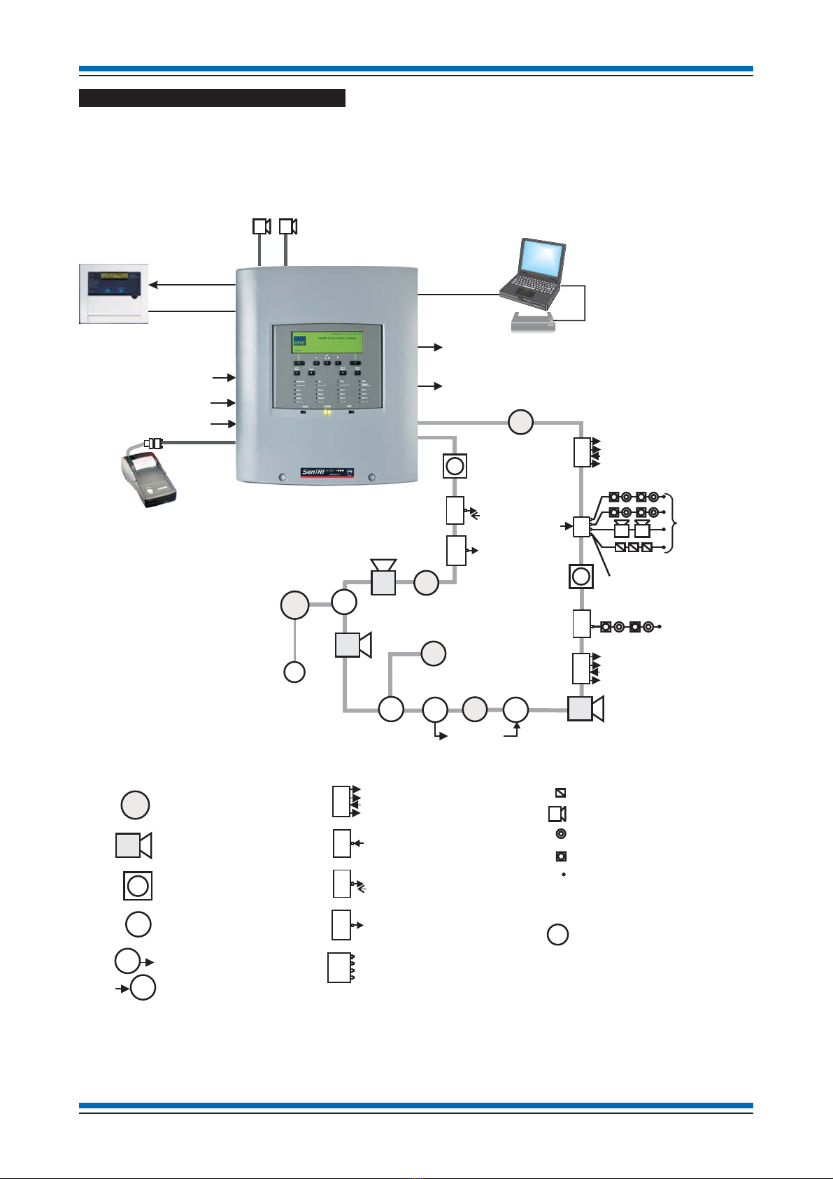
SenTRI ONE System Architecture -------10
SenTRI ONE panel -----------11
Features ····················· 11
Technical data ----------------12
Control panel ·················· 12
Power supply ·················· 13
Panel installation ------------14
How to disassemble the panel to gain
access to the Backbox-------------14
How to mount the backbox and
dedicated cable entry points ----------15
Flush Mounting the backbox ---------16
Refitting the electronics module --------16
Cable termination on enclosure --------17
Wiring test ···················· 17
Mains supply -----------------18
Mains and battery supply connections ······18
Removable terminal blocks ----------18
Terminals for external circuits on
Main Control Board -------------19
Device loop circuit --------------20
Master alarm circuits -------------21
Common Fault contacts ------------21
Fire Output contacts -------------22
Repeat indicator panel ------------22
External Evacuation input -----------23
Class Change input --------------23
RS232 Port------------------ 23
USB Port------------------- 23
Battery installation --------------24
On completion of panel installation ------25
Repeat Indicator panel ----------26
Technical data ----------------26
Installation ------------------26
S-Quad Sensors -------------27
General specification -------------27
Base ---------------------27
Base Gasket -----------------27
Base labels ------------------ 27
Indicators ------------------27
Dust Cover ------------------27
Do'sandDon't----------------27
Siting --------------------27
Metal back box ----------------28
In - Out wiring to SenTRI bases --------28
Programmable input/output ----------28
Tools for S-Quad ------------29
To remove a SenTRI device ----------29
To fit a SenTRI device ------------29
To fit a dust cover --------------29
To remove a dust cover ------------29
SenTRI device Semi-flush fixing kit
(SEN-FLUSH) -------------30
Technical data ----------------30
Beam sensor (Supported)---------31
Technical Data ----------------31
Installation ------------------32
Parallel bracket assembly ············ 32
SenTRI Speech, Sounder Strobe mark II - 33
Technical data ----------------33
Installation ------------------34
Retrofitting a System SenTRI device ······34
Manual Call Points -----------35
Glass or Resettable element options ·······35
Optional Back box ··············· 35
Technical data ----------------35
Installation ------------------35
Keyswitch Interface / MCP--------37
Keyswitch assembly -------------37
Back box ···················· 37
Technical data ----------------37
Installation ------------------38
Operation ------------------38
Label --------------------38
Features -------------------39
Cables --------------------39
Installation ------------------39
Interface Modules for SenTRI - Low voltage
(LV) Input/Output ------------39
Wiring diagrams ---------------40
Technical data ----------------41
Installation instructions
2