TAKEDO ENERGY USER MANUAL Release 3.1 dated 05-11-15
7
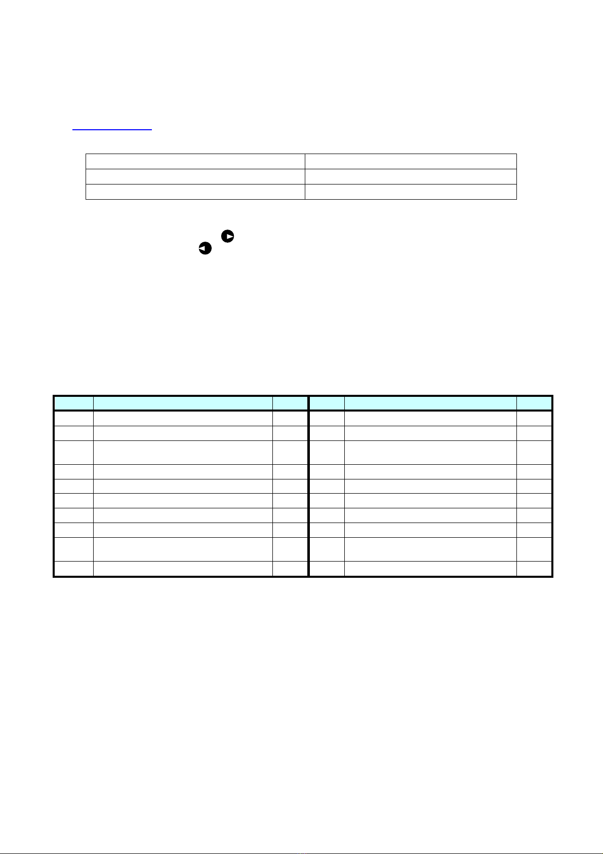
7.4 M4 = ACTIVE FAULTS AND WARNINGS
Listed below are the most common fault messages. Be careful not to reset the alarm or fault without first
having investigated the problems that caused the protection mechanism to cut in.
Always deselect the run command before resetting any fault.
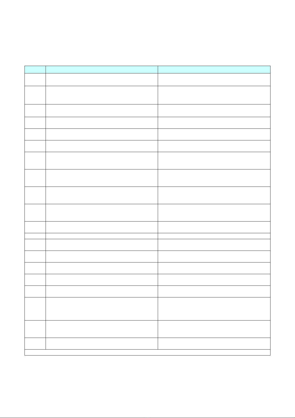
Code Description Remedies / Indications
1
Overcurrent: current 4 times the nominal value
detected at the inverter output.
Check the condition of cables connected to
L1,L2,L3. Check insulation of LCL filter.
2
Overvoltage: bus voltage is too high.
Check that during the main inverter braking
phase, the voltage between B + and B-do not
exceed 800Vdc.
5 Charge switch: The charge switch is open when
the drive is in running.
Reset the fault and restart . If the fault happens
again, contact SMS.
7
several potential causes,
including a faulty component.
Cannot be reset from the keypad. Switch off
power and don’t reconnect it. Contact SMS.
8
-Component damaged
-Malfunction.
Reset the fault and restart . If the fault happens
again, contact SMS.
9
Undervoltage: BUS voltage is too low. Check that the voltage input to the inverter is
correct and steady.
10
11
Detection of fault in power connections (input or
output phase missing, earth fault, etc.).
Check the power cables on the input/output sides
and/or the insulation of LCL filter.
14
16
Temperature inverter undertemperature (-10°C)
inverter overtemperature (+90°C)
motor overtemperature.
Make certain the air flow around the drive is
sufficient to cool the heat sink and/or check for
possible motor overload.
22
23
- Parameter recovery failed
- Damaged or malfunctioning component
Reset the fault and restart .
If the fault happens again, contact SMS.
25
- operational fault
- component failure
Reset the fault and restart.
If the fault happens again, contact SMS.
26
Start-up of the inverter has been impeded. Cancel prevention of inverter start-up.
Contact SMS.
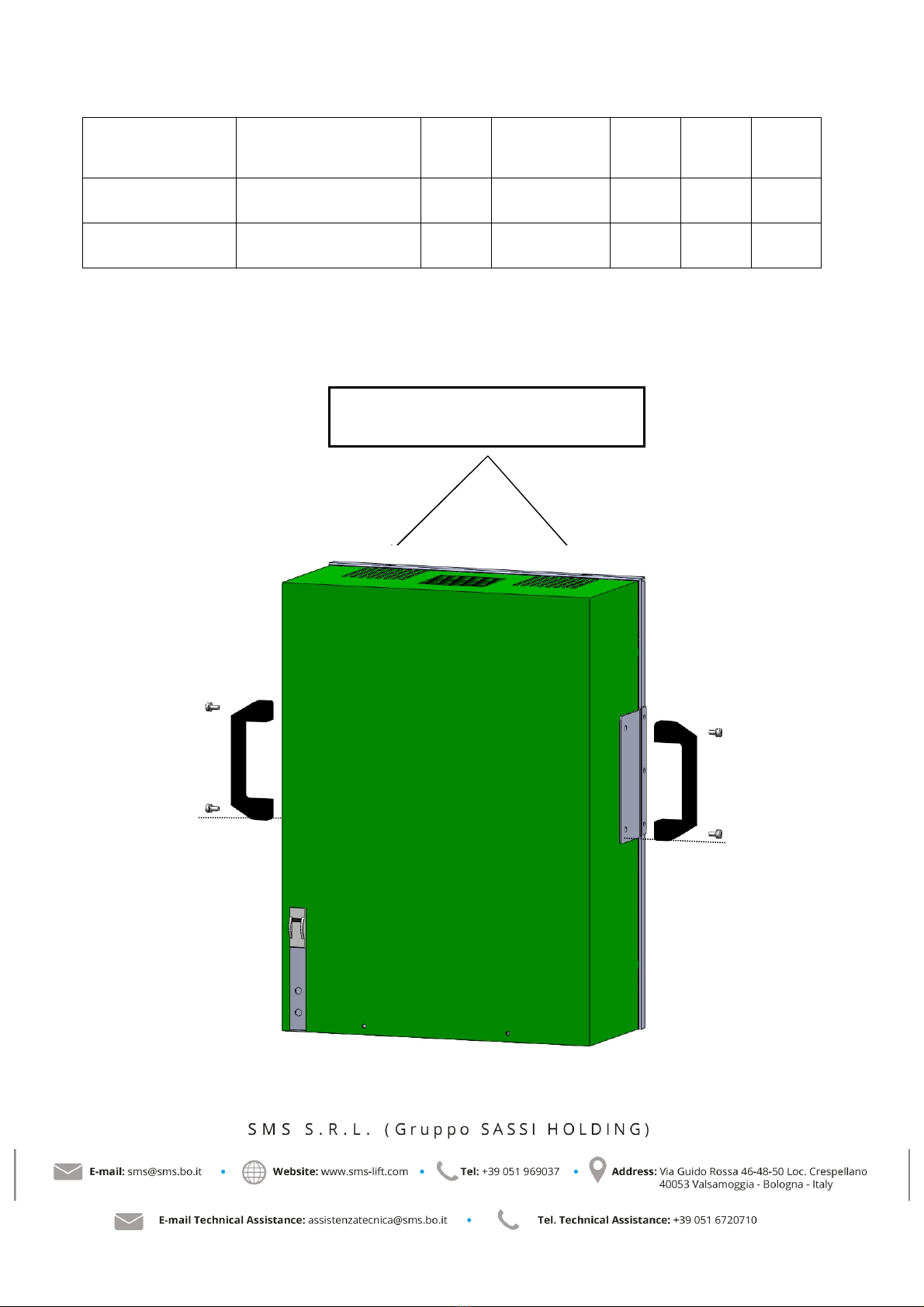
36
The control unit can’t control the
power unit and vice versa. Replace the control unit.
37
Optional board or control unit
changed. Reset
38
An optional board or power unit
with different nominal rating has been added. Reset
39
An optional board or power unit
has been removed. Reset
40
Unknown optional board or drive. Reset
41
IGBT temperature: IGBT Inverter Bridge
overtemperature protection has detected a short
term too high overload current.
Check device sizing.
Reduce the current limit of the device (requires
the keypad). Check the correct operation of the
cooling fan.
52
Keypad communication error:
The connection
between the control keypad and the frequency
converter is broken.
Check keypad connection and possible keypad
cable.
54
Optional board or connection slot
faulty.
Check board and slot
Contact SMS. .
If other types of fault should occur, please contact SMS.