SMW Autoblok LPS 4.0 14 IO User manual
Type LPS 4.0 14 IO
LINEAR POSITION SENSOR
DEUTSCH
INSTRUCTION MANUAL
Date:
Version:
Language:
COPY OF THE
ORIGINAL
2020-02
4
English

SMW-AUTOBLOK 3
4
5
6
7
9
11
1
20
21
22
23
25
1
27
21
Übersicht
INSTRUCTION MANUAL
Linear Position Sensor
Type LPS 4.0 14 IO
Thank you for purchasing an Original-SMW-AUTOBLOK Linear
Position Sensor LPS 4.0
.
This instruction manual contains the installation, the use and the
maintenance instructions of the „
LPS 4.0
“.
SMW-AUTOBLOK reserves the right to make changes without
notice.
This instruction manual is a part of the „
LPS 4.0
“and must be
passed to the new owner in case of sale.
This instruction manual may not be -in whole or in part- copied
without our written agreement.
Content
Overview
Declaration of incorporation
General safety instructions
Technical data
Signal output
Mounting
IO-Link Process structure and parameters
Maintenance
Toubleshooting
Accessories
Typeplate
Warranty
Confirmation of receipt of the manual
with analog interface 0..10V and IO-Link Interface
Measuring range 0..14mm
&Please read the instruction manual carefully
before installation and use and always follow the
regulations.
Please note especially the sections which are
marked with the following signs:
•Danger of injury or danger to life if instructions
are not followed.
•Danger of damage to the sensor, the machine or
the components.

4 SMW-AUTOBLOK
Einbauerklärung
208106
LPS 4.0 14 IO
Linear Position Sensor
Englisch
Signature of responsible person
SMW-Autoblok Spannsysteme GmbH
Wiesentalstraße 28
88074 Meckenbeuren
Deutschland / Germany
Tel.: +49 (0) 7542 - 405 0
Product description:
Type:
Ident-No.:
Declaration of incorporation
for a partly completed machinery
to machine directive 2006/42/EC
Date:
Due to its concept and design as it is introduced into the market is according to the following general safety
and health EU regulations.
Machine directive:
EMI directive:
The manufacturer:
herby declares, that the following product:
20.06.2018
Declaration of incorporation
2006/42/EC
2004/108/EC
Applied harmonized norms:
Emission:
Immunity:
EN 61000-6-3
EN 61000-6-2

SMW-AUTOBLOK 5
Allgemeine Sicherheitshinweise
Englisch
1. Intended use
The linear positioning sensor is exclusively intended
to be used as a parts of a production machine. The
sensor must only be installed and operated by personal
authorized and advised by the operation, that is qualifi ed
according to the valid national laws and according to the
national and international regulations. Any other use is
a non authorized use, and can cause hazards to health
and life of persons as well as damage to material.
The sensor must only be used in perfect functioning
condition. The advises of this manual must always be
observed.
For any other use than the intended use or any other
use than authorised by the manufacturer the operator
is sole and fully responsible. Any changes carried out at
the sensor must be authorised by the manufacturer and
must be documented properly.
In addition to this manual all laws, norms and regulations
must be observed.
General safety instructions
!
5. Safety
Always follow the regulations concerning safe working,
protection clothes and any other protection devices to
be used at the corresponding production machine.
2. Safety requirements
In order to protect the unit against fi re, electric shock
or potential destruction of the electronic components,
it must never be exposed to rain or extreme humidity.
Direct sun or heat are to be avoided as well.
3. Calibration, recalibration
The linear positioning sensor is adjusted and calibrated
at the factory for the measuring path specifi ed.
If the linear positioning sensor is not used as an absolute
measuring system, recalibration is not necessary.
If you are in doubt, please contact the manufacturer.
A recalibration can only be carried out in the factory.
4. Warranty and avoiding of harms
This manual is the basis for installation, use and
opertation of the linear positioning sensor.
Before using the linear positioning sensor read the
manual carefully. This manual must remain stored at the
machine where the linear position sensor installed.
All operations described in this manual must only
be carried out by capable personal authorized by the
operation.
6. General safety advises
• All safety advises, national and international
regulations to avoid accidents as well as company
internal working and operation advises have to be
observed.
• Any conditions causing hazards have to be avoided.
• Interferences that can cause hazards have to be
eliminated immediately.
• Ignoring the safety instructions can cause hazards to
persons, environment and / or can cause damage and
will make any warranty void.
• During installation, the installation and maintenance
of the linear positioning sensor all safety regulations
of the machine, into which the sensor is installed,
must be observed.
• Prior to any runoff this manual must read, and all
safety advises must be followed.
• The manufacturer refuses any claims for problems
caused by not following this manual.
7. Safety advises for operation
• When using the linear positioning sensor in safety
relevant operations, precautions must be taken to
avoid danger for personal and machine, in case of
failure of the sensor. This can be done by posting
safety advises on the machine or by adding safety
advises to the manual of the machine. Additionally
the machine maker can add suitable (mechanical)
protections , to avoid any hazards. We also refer to
the trouble shooting.
• The installation and run off must be carried out by
qualifi ed personal. All safety regulations for electronic
installations must be observed.
• The sensor must not be opened at all!
• Before use all connections must be double checked
carefully.
• Never touch the sensing surface (opposed to the plug)
with sharp or tipped articles. Use a soft tissue only.
Insuffi cient or improper maintenance makes any warranty
from SMW-AUTOBLOK void.
In case of problems or questions please contact SMW-
AUTOBLOK directly or one of our authorized offi ces.
!
!
!
!
!
!
!
!

6 SMW-AUTOBLOK
25
35
35
LED
Ø4,3 (2x)
15
M8x1
40
20
30,5
(9)
25,3
25
35
35
LED
Ø4,3 (2x)
15
M8x1
40
20
30,5
(9)
25,3
A
A
B
B
α
α
Technical description
Pin assignment connectors M8 x 1
Pin Description
1 24V DC
2 Signal output 0-10 V
3 GND
4 C/Q (Data)
LPS 4.0 14 IO
Power supply 24VDC ±10%@ 35mA typ. Inverse-polarity and overvoltage protection
Interface 0...10V, short-circuit-proof, oad > 2 kOhm, IO Link 1.0
Function monitoring on error: output 0V
Resolution ca. 5 mV
Reproducibility ±0,05 mm
Linearity ±0,2 mm
Temperature drift ±0,25mm through the whole operating, temperature range, temperature engaged
Measuring frequency 33 Hz
EMV Compatiblity EN61000-6-2 Immunity / EN61000-6-4 Emision
Power-on phase The first measuring value is available after 3 sec. approximately
Case dimensions L x W x H; 35 x 35 x 30,5 mm
Case material Plastic/Metal
Case protection class IP 67
Mounting via threaded holes for M4 screws
Operation and storing temperature ranges 0 to 75°C
Connections 4-pin connector M8x1, male
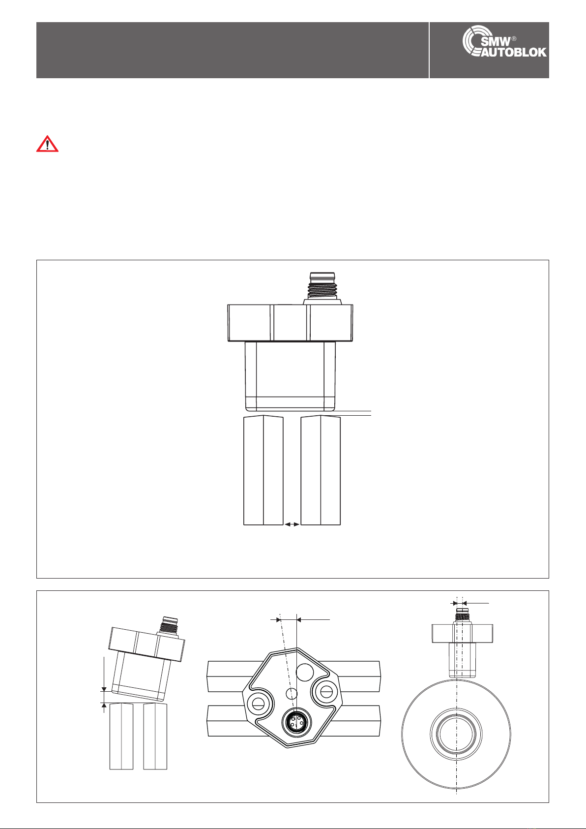
Dimensions Info
Distance A = 1.0 mm ± 0.25 A = recommended distance (inside and parallel) between the measuring surface
and the Shiftring (ring shape)
Width B = 11 mm B = recommended width of the Cam or Shiftring
Angle α = 6° α = Angle min. 6°
Dimensioning Cam / Shiftring
Recommended dimensions of Cams / Shiftrings:
Cam
Example of a cam
Shift ring
Example for an shift ring

SMW-AUTOBLOK 7
Analog interface
Technical description
The following pin assignment applies to the 4-pin cable connectorM8x1
Pin assignment, analog
Pin Description Comment 4-pin cable
1 24V DC +/- 10% brown
2 Signal out 0..10V white
3 GND blue
4 CQ (Data) must not be used black
Use only 4-pin shielded cable
Use only 4-pin shielded cable. GND is used for power supply
and signal. Shield connected on one side at the female
connector.
The pin assignment is binding
The pin assignment is binding. The lead colours of the cable
may vary.
The LPS 4.0 with analog signal outputs provides 0...10V,
corresponding to 0...14mm. If there is an upper or lower
deviation from the measuring range or in case of an error, 0V or
0mA is output.
LPS 4.0 14 connection cable, angulated LPS 4.0 14 connection cable, straight
Pin assignment connectors M8x 1
Pin Description
1 24V DC
2 Signal output 0-10 V
3 GND
4 C/Q (Data)

8 SMW-AUTOBLOK
Signal output
After the module has been assembled, the cable is connected to
the PLC control via a shielded connection cable according to the pin
assignment. Only 3 of the 4 wires are relevant for the user.
The other two must neither be stripped nor used for any other
purposes. The shield should be connected all over and possibly on
both sides. Differences in the shield ground(s) are to be avoided;
if need be, the shield may be connected only on one side. The
securing screw of the M8 flanged connector must be tightened
moderately.
Do not lay connection cables in parallel to cables!
Do not lay connection cables in parallel to cables which
could cause interferences.
Consider cable crosssection and cable length!
Per ohm copper resistance, about 35mV offset are added to
the measuring signal. Cable crosssection and cable length
are to be taken into account.
Analog connection Electric power
When connecting the test sensor to power, all safety advises
of the machine or of the external unit (see the corresponding
manuals) have to be observed.
The connection must only be carried out by qualified
personal.
SMW-AUTOBLOK 9
<±0,5°
<±1,5°
<±0,25°
Mounting LPS 4.0
Special care must be taken when mounting
Special care must be taken when mounting the sensor
module since correct mounting is decisive for the quality of
the measurement signal.
The following procedure is recommended:
• Mount the LPS 4.0 by means of a support (not contained in the
• delivery package).
• Set the exact distance to the switch ring (ring shape) or cam.
• Take care that the sensor module is in an exact parallel position
to and is concentric with the cylinder axis.
• No minimum distance to metal surfaces has to be observed on
the sides, the front and the side facing the support; a distance
of 10mm must be kept towards the measuring surface opposite
the support..
Switch
ring
Mounting
The mounting positions shown above are not admissible and must be avoided under all circumstances.
LPS 4.0 scale drawing with tolerances
air gap to switch ring or cam
Measuring range 14 mm

10 SMW-AUTOBLOK
Notes
Englisch

SMW-AUTOBLOK 11
15 14 13 12 11 10 9 8 7 6 5 4 3 2 1 0
0
AD9 AD8 AD7 AD6 AD5 AD4 AD3 AD2 AD1 AD0 res res res BD3 BD2 BD1
BDn 0
1
AD
1021
1022
1023
Notes
Englisch
IO-Link Process Data Structure and Parameters
Input data structure
Position value
Function
BD1 Switching signal 1
BD2 Switching signal 2
BD3 Switching signal 3
AD Position value
Values
bool Switched off
Switched on
0...448 Valid position value in 1/32 mm
Outside of the value range
(below the value range)
Outside of the value range
(above the value range)
No target

12 SMW-AUTOBLOK
1 0x00
2 0x01
3 0x02 0x17
4 0x03 0x01
5 0x04 0x10
6 0x05 0x50
7 0x06 0x00
8 0x07 0x04
9 0x08 0x46
10 0x09 0x03
11 0x0A 0x2C
12 0x0B 0xEA
13 0x0C 0x00
14 0x0D 0x00
IO-Link Process Data Structure and Parameters
Configuration
BD1 switchpoint logic Index 0x3D Subindex 1
0 (High-Active) 1 (Low-Active)
BD1 - switching signal 1:
Target outside of the limits 0 1
Target within the limits 1 0
BD2 switchpoint logic Index 0x3F Subindex 1
0 (High-Active) 1 (Low-Active)
BD2 - switching signal 2:
Target outside of the limits 0 1
Target within the limits 1 0
IO-Link Communication and ID Parameters
Direct Paramter Page 1 - Index 0x00
Sub Address
hex
Name Type Data
type
Attribute Value Comment
Communication Control
Master Command R/W uint8 volatile written by master
Master cycle time R/W uint8 volatile written by master
Min. cycle time R uint8 constant 2.3 ms
Frame Capability R uint8 constant ISDU support
IO-Link Version ID R uint8 constant IO-Link version 1.0
Process Data in R uint8 constant 16bit Pdin, SIO support
Process Data out R uint8 constant n/a
Validation Parameter
IO-Link Vendor ID1 (MSB) R uint8 constant SMW Autoblok
IO-Link Vendor ID2 (LSB) R uint8 constant
Device ID1 (MSB) R uint8 constant
Device ID2 R uint8 constant
Device ID3 (LSB) R uint8 constant
not used
BD3 switchpoint logic Index 0x400
0 (High-Active 1 (Low-Active)
BD3 - switching signal 3:
Target outside of the limits 0 1
Target within the limits 1 0
Function ID1 (MSB) R/W uint8 static
Function ID2 (LSB) R/W uint8 static

SMW-AUTOBLOK 13
1 0x0001
2 0x8000
3 0x8001
4 0x8002
5 0x8004
1 0x010300
2 0x020A06
0x10
0x11
0x12
0x13
0x14
0x15
0x16
IO-Link Process Data Structure and Parameters
IO-Link Standard Parameters
System Command (Index 0x02)
Value hex Value dec Function
0x40 64 Teach Apply
0x41 65 SP1 Single Value Teach
0x42 66 SP2 Single Value Teach
0x4F 79 Teach Cancel
0x82 130 Restore Factory Settings
Profile ID (Index 0x0D)
Subindex Value hex Function
Smart Sensor Profile supported
Device Identification
Binary Data channel
Process Data Variable
Teach Channel
PD input descriptor (Index 0x0E)
Subindex Value hex Function
SetFBool3.0
UIntegerT10.6
Parameters for Identification
Index hex Index dec Name Type Data type
16 Vendor Name R char [31]
17 Vendor Text R char [max 32]
18 Product Name R char [max 32]
19 Product ID R char [11]
20 Product Text R char [max 32]
21 Serial Number R char [14]
22 Hardware Revision R char [7]

14 SMW-AUTOBLOK
3
1
2
3
IO-Link Process Data Structure and Parameters
IO-Link Device Parameter
Note:
The existing indexes for the various sensors differ according to their properties. For example, indexes for parameterizing an analog out-
put are only available for sensors with an analog output.
Index
hex
sub Name Type Data type Value Default Unit
Smart Sensor Profile Parameters
0x3A Teach-In Channel R/W unit8 0...3 0
0x3B Teach-In Status R unit8
0x3C BD1_SPV -
Switching signal 1
R/W record
1 SP1- set point
value 1
R/W unit16 0...448 112 1/32mm
2 SP1- set point
value 2
R/W unit16 0...448 144 1/32mm
0x3D BD1_SPC -
Switching signal 1
configuration
R/W record
1 switchpoint logic R/W unit8 0x00 not inverted
0x01 - inverted
0x02 - 0xFF - not allowed
0x00
2 switchpoint mode R/W unit8 0x00 - inactive
0x01 - single point mode
0x02 - window mode
0x03 - two point mode
0x04 - 0x7F - reserved
0x80 - centered window mode
0x80
switchpoint
hysteresis
R/W unit16 0: Normal
1: Medium
3: High
1
0x3E BD2_SPV -
Switching signal 1
R/W record
1 SP1 - set point
value 1
R/W uint16 0...448 224 1/32mm
2 SP2 - set point
value 2
R/W uint16 0...448 256 1/32mm
0x3F BD2_SPC -
Switching signal 1
configuration
R/W record
switchpoint logic R/W uint8 0x00 - not inverted
0x01 - inverted
0x02 - 0xFF - not allowed
switchpoint mode R/W uint8 0x00 - inactive
0x01 - single point mode
0x02 - window mode
0x03 - two point mode
0x04 - 0x7F - reserved
0x80 - centered window mode
switchpoint
hysteresis
R/W uint8 0: Normal
1: Medium
2: High

SMW-AUTOBLOK 15
0x40
IO-Link Process Data Structure and Parameters
Index
hex
sub Name Type Data type Value Default Unit
0x4000 BD3_SPV -
Switching signal 1
R/W record
1 SP1 - set point
value 1
R/W unit16 0...448 336 1/32mm
2 SP1 - set point
value 1
R/W unit16 0...448 368 1/32mm
0x4001
BD3_SPC - Switching
signal 1 configuration
R/W record
1 switchpoint logic R/W uint8 0x00 - not inverted
0x01 - inverted
0x02 - 0xFF - not allowed
0x00
2 switchpoint mode R/W uint8 0x00 - inactive
0x01 - single point mode
0x02 - window mode
0x03 - two point mode
0x04 - 0x7F - reserved
0x80 - centered window mode
0x80
3 switchpoint
hysteresis
R/W uint16 0: Normal
1: Medium
2: High
1
Device specific operation parameters
Centered Window
Width
R/W record
1 BD channel 1 width R/W uint16 0...448 32 1/32mm
2 BD channel 2 width R/W uint16 0...448 32 1/32mm
3 BD channel 3 width R/W uint16 0...448 32 1/32mm
0x42
AD_SPC - Analog
Signal Set Point Value
R/W record
1 SP1 - set point
value 1
R/W uint16 0...448 0
2 SP1 - set point
value 2
R/W uint16 0...448 448
0x43 AD_SPC -
Analog Signal
Configuration
R/W record
1 Analog Output
Mode
R/W uint8 0x00 - Rising Ramp
0x01 - Falling Ramp
0x00
2 Error Value
Hysteresis
R/W uint16 0: Normal
1: Medium
2: High
0
3 Error Replacement
Value
R/W uint8 0b0000 0000 - disabled
0bXXXX XXX1 - out-of-range
enabled
0bXXXX XX1X - no target
enabled
0

16 SMW-AUTOBLOK
IO-Link Process Data Structure and Parameters
Index
hex
8sub9 Name Type Data type Value Default Unit
0x5F Measurement Data
Collection
R record
1 Position value R uint16 0...448 1/32mm
2 Signal quality R uint8 0x00 - insufficient / no position
acquisition possible
0x01 - acceptable
0x02 - good
0x03 - excellent
3 BD1 Status R uint8 0: inactive
1: active
4BD2 Status R uint8 0: inactive
1: active
5 BD3 Status R uint8 0: inactive
1: active
Standard operation control
0x70 Output
Configuration
R/W record
1 Output Type Q1 R/W uint8 0x00 - push-pull
0x01 - low-side
0x02 - high-side
2 reserved R/W uint8 0x00 - reserved
0x01 - reserved
0x02 - reserved
0x03 - reserved
3 reserved R/W uint8 0x02 - reserved
0x03 - reserved
4 Analog Output
Type UI
R/W uint8 0x00 - reserved
0x01 - reserved
0x02 - reserved
0x03 - U: 0...10V
0x04 - U: 1...5V
5 reserved R/W uint8 0...200 0
6 reserved R/W uint8 0...200 200
7 Voltage Low Value R/W uint8 0...100 0 0.1V
8 Voltage High Value R/W uint8 0...100 100 0.1V

SMW-AUTOBLOK 17
IO-Link Process Data Structure and Parameters
Index
hex
8sub9 Name Type Data type Value Default Unit
0x74 Event
Configuration
R/W uint8 0b0000 0000 - application events
disabled
0bXXXX XXX1 - no target event
enabled
0x00
1Locator Indication
Control
R/W uint8 0x00 - normal indication
0x01 - locator indication
0x00
User information
0xC0 UT1 - User Tag 1 R/W uint32 0x00000000...
0xFFFFFFFF
0
0xC1 1 UT2 - User Tag 2 R/W uint16 0x0000...
0xFFFF
0
Special function
0xE2 Operating
Temperature
R int8 °C
0xE8 Device
characteristics
R record
1 Position Range R uint16 448
2 Resolution R uint16 16 1/512mm

18 SMW-AUTOBLOK
Note: At parameter „0xEC“ it is only possible to read the complete parameter. Accessing of subindexes is not possible here.
Index
hex
sub Name Type Data type Value Default Unit
Event Configuration (Data Storage = yes)
0x78 1 No Target
(Warning)
R/W bool 0: Disabled
1: Enabled
2 Signalfehler R/W bool 0: Disabled
1: Enabled
Service Function (Data Storage = no)
0x7F Indication
Setting
R/W unit8 0: Normal Indication
1: Locator Indication
0
Device Access Locks (Data Storage = yes)
0x0C Data Storage
Lock (Bit1)
R/W bool 0: false (Data Storage
activated)
1: true (Data Storage
locked)
0
Device Status Information (Data Storage = no)
0x24 Device Status R unit8 0: Device is OK
2: Out of specification
0
0x25 Detailed Device
Status
R unit 8 [9] Active Events, see IOLink
1.1-Specification
Operation Information (Data Storage = no)
0xE0 Operating Hours R unit32 0: 0x3FFFFFFF
Resolution 0,25h
0,25h
User Specific Information (Data Storage = yes)
0x18 Application
Specific Tag
R/W char [32] Always a step ahead
0xC0 User Tag R/W char [32] LPS 4.0 Series
Device Characteristics (Data Storage = no)
0xE8 1 Position Range R unit16 LPS 4.0 14: 0...960
2 Resolution R unit16 50 µm
Process Data (Data Storage = no)
0x28 Process Data
Values
R unit16 See Process Data
Structure
Observation (Data Storage = no)
0xEC 1 Measured Value R unit16 LPS 4.0 14: 0...960 1/20 mm
2 Signal Quality R unit8 0: Insufficient
1: Acceptable
2: Good
3: Excellent
3 Switching Signal 1 R unit8 0: Inactive
1: Active
4 Switching Signal 2 R unit8 0: Inactive
1: Active
5 Switching Signal 3 R unit8 0: Inactive
1: Active
IO-Link Process Data Structure and Parameters

SMW-AUTOBLOK 19
Error Codes
In case of a fault, the sensor transmits the error codes detailed in the following table. The error code consists of 2 bytes. The higher value
byte, here 0x80, represents the IO-Link device as the emitter. The lower value byte represents the actual fault.
Error Error code Comment
Index unavailable 0x8011 R/W access to unavailable parameter index.
Unavailable subindex 0x8012 R/W access to unavailable parameter subindex.
Service temporarily unavailable 0x8020 Write/read access to parameter limited by the device status is not
possible.
Access denied 0x8023 Write attempt to read-only address.
Invalid value range,
parameter
0x8030 For all R/W parameters outside of the valid value range.
Parameter value too large 0x8031 For all R/W parameters above the valid value range.
Parameter value too small 0x8032 For all R/W parameters beneath the valid value range.
Event Data
The sensor is capable of transmitting events that occur:
Event Instance Type Mode Event
Qualifier
Event
Code
Description
PDU
Buffer overflow
DL Error Single shot 0x72 0x5200 Size of the transmitted data
package can not be processed
by the sensor
PDU
Checksum error
DL Error Single shot 0x72
PDU
Procedure error
PDU
Flow control
error
DL Error Single shot 0x72 0x5600 Asynchrony in the transmission
of the PDU data
Restricted
PDU service
AL Error Single shot 0x73 0x5800 Submitted service request is
invalid
No damping
element
APP Warning Appear/
Disappear
0xE4/0xA4 0x8CA4 No damping element or
no position determination
possible
IO-Link Process Data Structure and Parameters

20 SMW-AUTOBLOK
Maintenance
Maintenance, service
The LPS 4.0 usually works without maintenance.
Any way the function should be tested in regular intervals when testing the machine tool.
The following tests need to be carried out:
• Check the relative position of the sensor to the cam of the cylinder.
• Check if all mounting bolts are tightened correctly and check the cam of the cylinder.
• Check the switch ring.
• Check that the sensing surface has no physical damage.
• Check that there is no contamination of the sensor.
This manual suits for next models
1
Table of contents
Other SMW Autoblok Accessories manuals


Popular Accessories manuals by other brands


Sensata
Sensata Nanoprecise 6VW quick start guide

AGI
AGI Batco 1500 Series: Batco FX1535FL Assembly manual

MICRO-EPSILON
MICRO-EPSILON thermoMETER CTVideo instruction manual

Knick
Knick SE 503 Series Instructions for use

Kogan
Kogan SMARTERHOME KARMDF200BA user guide

Nittan
Nittan Sensortec ST-PY-AS instruction manual


