Hach GA2 00 Series User manual

DOC344.52.93153
ORBISPHERE Model
GA2X00 O2 EC Sensor
11/2019, Edition 2
User Manual


Table of Contents
Section 1 Specifications........................................................................................ 3
1.1 Sensor specifications............................................................................................ 3
1.2 Sensor configurations........................................................................................... 4
1.3 Sensor membrane specifications.......................................................................... 4
1.3.1 Oxygen sensors (Table 1).......................................................................... 4
1.3.2 Oxygen sensors (Table 2).......................................................................... 5
Section 2 General information............................................................................ 6
2.1 Safety information................................................................................................. 6
2.1.1 Use of hazard information.......................................................................... 6
2.1.2 Precautionary labels................................................................................... 7
2.2 Product overview.................................................................................................. 7
2.2.1 Operating principle..................................................................................... 7
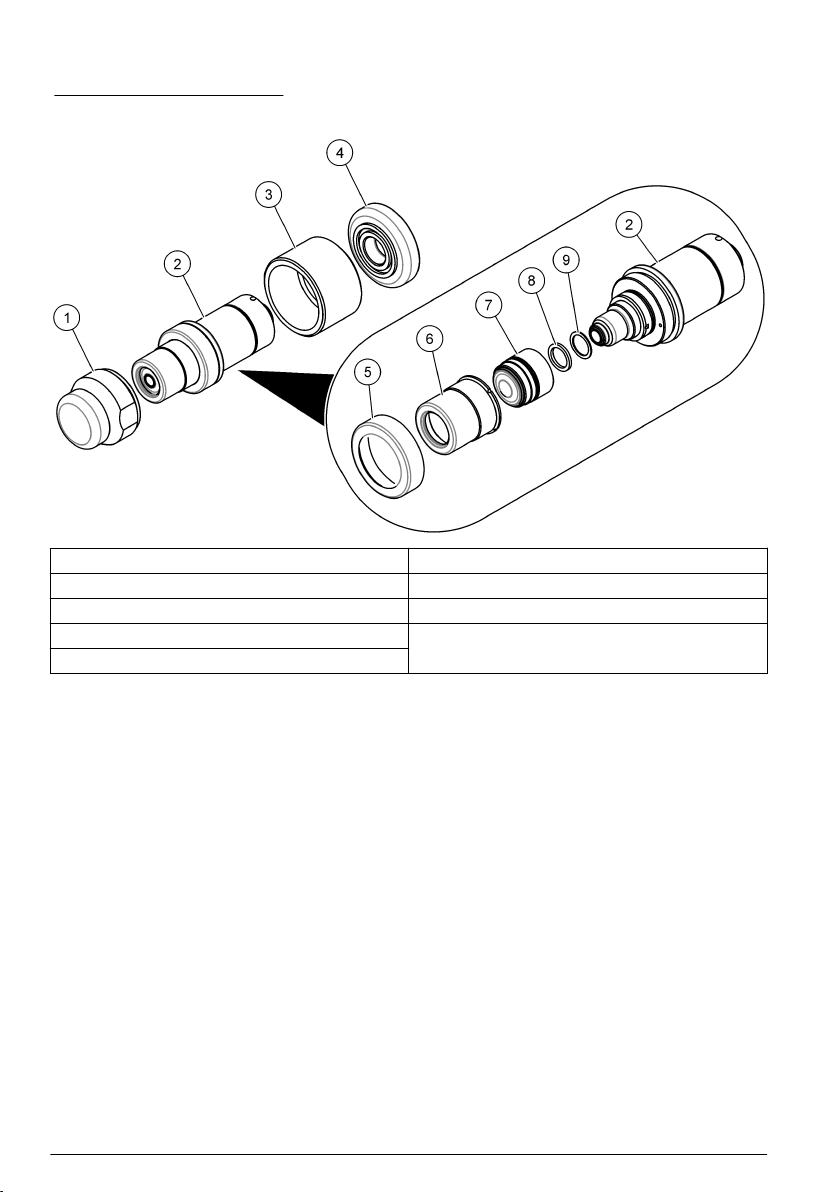
2.2.2 Sensor components.................................................................................... 8
2.3 Product components............................................................................................. 8
2.3.1 Electrochemical sensor.............................................................................. 9
2.3.2 Protection caps........................................................................................... 9
2.3.3 Sensor recharge kit.................................................................................... 9
Section 3 Installation............................................................................................. 10
3.1 Sensor preparation............................................................................................. 10
3.2 Sensor installation.............................................................................................. 13
3.2.1 Sensor positioning information................................................................. 13
3.2.2 Sensor insertion........................................................................................ 14
3.2.3 Sensor removal........................................................................................ 14
3.3 Accessories installation...................................................................................... 15
3.3.1 External pressure sensor.......................................................................... 15
3.3.2 Weld-on stainless steel socket................................................................. 15
3.3.3 The 32003 insertion/extraction valve........................................................ 16
3.3.4 The 33095 sensor housing....................................................................... 17
3.3.5 Tuchenhagen Varivent® in-line access unit.............................................. 17
3.3.6 ORBISPHERE flow chambers.................................................................. 18
3.3.7 Multi-parameter flow chamber.................................................................. 19
Section 4 Maintenance......................................................................................... 20
4.1 Maintenance schedule........................................................................................ 21
4.2 Prerequisites for sensor maintenance................................................................ 21
4.3 Membrane replacement and sensor head cleaning............................................ 22
Section 5 Troubleshooting................................................................................. 28
5.1 Oxygen sensor.................................................................................................... 28
Section 6 Replacement parts and accessories......................................... 29
1

Table of Contents
2

Section 1 Specifications
Specifications are subject to change without notice.
1.1 Sensor specifications
Table 1 ORBISPHERE family of GA2X00 oxygen sensors
Specification Details—Non-ATEX sensors Details—ATEX sensors
Type Electrochemical oxygen sensor
Dimensions (Ø × L) 32 × 86.3 mm (1.26 × 3.40 in.) Refer to Figure 1.
Weight 300 g
Pressure resistence 40 bar maximum with default PPS collar (100 bar with stainless steel collar)
Materials Stainless steel Stainless steel or hastelloy
Sensor head: Kalrez® O-rings
Sensor bottom: Viton® O-rings1
EPDM and Kalrez® O-rings
Sensor head: Kalrez® O-rings
Sensor bottom: Viton® O-rings or Kalrez® O-rings
Other Smart capability Intrinsically safe
Certification CE CE, Ex II 1 G, Ex ia IIC T6
Note: Unlike the GA2400 non-ATEX sensors, the intrinsically safe GA2800 ATEX sensors have no smart capability
to store calibration data. However, all GA2800 ATEX sensors have the ATEX conformity information engraved on
the sensor itself.
Figure 1 Sensor dimensions
1Viton and Kalrez are trademarks of DuPont Corporation.
English 3

1.2 Sensor configurations
Table 2 Beverage
Application Sensor Membrane Cartridge Protection Cap
Beer with ORBISPHERE
3650 Portable
GA2400-S00 2958A-A (optimized response
time)
2952A-A (optimized
maintenance interval)
33051-SP
Beer in-line GA2400-S00 2952A-A 33051-SG
Wort in-line GA2400-S00 29552A-A 33051-S0
Wort with ORBISPHERE
3650 Portable and special flow
cell 32007W.xxx
GA2400-S00 29552A-A 33051-S0
ORBISPHERE 6110 Total
package analyzer (TPA)
GA2400-S00T 2956A-A 33051-ST
De-aerated water GA2400-S00 2956A-A or 2952A-A 33051-S0
33051-SG (if exposed to
CIP)
Table 3 Pure water applications (Power - Electronics)
Application Sensor Membrane Cartridge Protection Cap
On-line dissolved oxygen traces in pure water GA2400-S00 2956A-A 33051-S0
Dissolved oxygen traces with 3655 Portable GA2400-S00 2956A-A 33051-S0
Table 4 ATEX
Sensor Membrane Cartridge Protection Cap
GA2800-SVS 2956A-A or 29552A-A 33051-SG
GA2800--SKS 2956A-A or 29552A-A 33051-SG
GA2800--HVS 2956A-A or 29552A-A 33051-H0
GA2800--HKS 2956A-A or 29552A-A 33051-H0
1.3 Sensor membrane specifications
1.3.1 Oxygen sensors (Table 1)
Table 5 Membrane specifications - Oxygen sensors (1)
Specification 2956A-A 2958A-A 29552A-A 2952A-A
Recommended applications Corrosion control,
De-aerated water
Beverage,
Lab. applications
In line wort,
Air/O2 injection,
Sewage treatment
Corrosion control,
In line beverage,
De-aerated water
Material PFA Tefzel® 2PTFE Tefzel®
Thickness [μm] 25 12.5 50 25
Calibration gas Air Air Air Air / Pure O2
Dissolved measurement range 0 ppb to 20 ppm 0 ppb to 40 ppm 0 ppb to 80 ppm 0 ppb to 80 ppm
2Tefzel is a trademark of DuPont Corporation.
4 English

Table 5 Membrane specifications - Oxygen sensors (1) (continued)
Specification 2956A-A 2958A-A 29552A-A 2952A-A
Gaseous measurement range 0 Pa to 50 kPa 0 Pa to 100 kPa 0 Pa to 200 kPa 0 Pa to 200 kPa
Accuracy The greater of
±1% of reading
or ± 0.1 ppb3,
or ± 1 ppb4,
or ± 0.25 Pa
The greater of
±1% of reading
or ± 1 ppb,
or ± 2 Pa
The greater of
±1% of reading
or ± 2 ppb,
or ± 5 Pa
The greater of
±1% of reading
or ± 2 ppb,
or ± 5 Pa
Integrated radiation dose limit
[rads]
2 x 104108N/A 108
Expected current in air @ 1 bar
25 °C [μA]
26.4 9.4 6.3 5.4
Expected current in pure O2 [μA] 132 47 31.4 27
O2 consumption in O2 saturated
water at 25 °C [μg/hour]
40 14 9.4 8
Temp. compensation range – 5 to 60 °C
Temp. measuring range – 5 to 100 °C
Response time57.2 sec. 9.5 sec. 90 sec. 38 sec.
Recommended min. liquid flow
rate6 [mL/min]
180 120 50 50
Recommended min. linear flow
rate6 [cm/sec]
200 100 30 30
Recommended gaseous flow rate
[L/min]
0.1 to 3
1.3.2 Oxygen sensors (Table 2)
Table 6 Membrane specifications - Oxygen sensors (2)
Specification 2935A-A 29521A-A 2995A-A
Recommended applications Saturated to super
saturated levels
Saturated to super
saturated levels
In line hot wort
(up to 70 °C)
Material Halar® 7Tefzel®Tefzel®
Thickness [μm] 25 125 12.5
Calibration gas Air / Pure O2Air / Pure O2Pure O2
Dissolved measurement range 0 ppb to 400 ppm 0 ppb to 400 ppm 0 ppb to 2000 ppm
Gaseous measurement range 0 Pa to 1000 kPa 0 Pa to 1000 kPa 0 Pa to 5000 kPa
Accuracy The greater of
±1% of reading
or ± 10 ppb,
or ± 20 Pa
The greater of
±1% of reading
or ± 10 ppb,
or ± 20 Pa
The greater of
±1% of reading
or ± 50 ppb,
or ± 100 Pa
3Accuracy is ± 0.1 ppb for 410, 510, 362x, 360x and 3655 instruments
4Accuracy is ± 1 ppb for 366x and 3650 instruments
5Response time at 25 °C for a 90% signal change
6Liquid flow through an ORBISPHERE 32001 flow chamber, with protection cap and no grille
7Halar is a trademark of Solvay Corporation.
English 5

Table 6 Membrane specifications - Oxygen sensors (2) (continued)
Specification 2935A-A 29521A-A 2995A-A
Integrated radiation dose limit [rads] N/A 108108
Expected current in air @ 1 bar
25 °C [μA]
0.9 0.7 0.2
Expected current in pure O2 [μA] 4.7 3.8 0.9
O2 consumption in O2 saturated
water at 25 °C [μg/hour]
1.4 1.3 0.3
Temp. compensation range – 5 to 60 °C
Temp. measuring range – 5 to 100 °C
Response time82.5 min. 18 min. 80 sec.
Recommended min. liquid flow rate9
[mL/min]
25 25 5
Recommended min. linear flow rate9
[cm/sec]
20 60 5
Recommended gaseous flow rate
[L/min]
0.1 to 3
Section 2 General information
In no event will the manufacturer be liable for direct, indirect, special, incidental or consequential
damages resulting from any defect or omission in this manual. The manufacturer reserves the right to
make changes in this manual and the products it describes at any time, without notice or obligation.
Revised editions are found on the manufacturer’s website.
2.1 Safety information
N O T I C E
The manufacturer is not responsible for any damages due to misapplication or misuse of this product including,
without limitation, direct, incidental and consequential damages, and disclaims such damages to the full extent
permitted under applicable law. The user is solely responsible to identify critical application risks and install
appropriate mechanisms to protect processes during a possible equipment malfunction.
Please read this entire manual before unpacking, setting up or operating this equipment. Pay
attention to all danger and caution statements. Failure to do so could result in serious injury to the
operator or damage to the equipment.
Make sure that the protection provided by this equipment is not impaired. Do not use or install this
equipment in any manner other than that specified in this manual.
2.1.1 Use of hazard information
D A N G E R
Indicates a potentially or imminently hazardous situation which, if not avoided, will result in death or serious injury.
WARNING
Indicates a potentially or imminently hazardous situation which, if not avoided, could result in death or serious
injury.
CAUTION
Indicates a potentially hazardous situation that may result in minor or moderate injury.
8Response time at 25 °C for a 90% signal change
9Liquid flow through an ORBISPHERE 32001 flow chamber, with protection cap and no grille
6 English

N O T I C E
Indicates a situation which, if not avoided, may cause damage to the instrument. Information that requires special
emphasis.
2.1.2 Precautionary labels
Read all labels and tags attached to the instrument. Personal injury or damage to the instrument
could occur if not observed. A symbol on the instrument is referenced in the manual with a
precautionary statement.
This is the safety alert symbol. Obey all safety messages that follow this symbol to avoid potential
injury. If on the instrument, refer to the instruction manual for operation or safety information.
This symbol indicates the need for protective eye wear.
This symbol indicates the need for protective hand wear.
Products marked with this symbol indicates that the product contains toxic or hazardous substances
or elements. The number inside the symbol indicates the environmental protection use period in
years.
Electrical equipment marked with this symbol may not be disposed of in European domestic or
public disposal systems. Return old or end-of-life equipment to the manufacturer for disposal at no
charge to the user.
2.2 Product overview
2.2.1 Operating principle
In its simplest form, the electrochemical sensor consists of one center electrode (cathode) and one
counter electrode (anode) immersed in an electrolyte solution which is separated from the gaseous
or liquid sample by a gas permeable membrane. An electronic circuit is linked to the anode and
cathode. Through an applied voltage, current will flow between the anode and the cathode.
A guard ring electrode surrounds the center electrode in order to reduce the influence of other gases
on the center electrode, and therefore improving analysis stability.
The sensor head is covered with a protection cap and, in some applications, a grille to protect the
membrane. Materials used for the components of the sensors differ with the application.
Gas penetrating through the membrane into the cell dissolves in the electrolyte. It undergoes a
reaction at the cathode, causing a measurable electric current to flow. This current is proportional to
the amount of gas entering the cell, which in turn is proportional to the partial pressure of gas in the
sample outside the cell.
The result is shown as gas concentration, which can then be displayed with a choice of several
measuring units, according to instrument setup.
The sensor also includes “smart sensor technology”, implemented using an RS485 interface.
The sensor electronics perform four functions:
• Apply constant voltage to the anode
• Measure the current flowing through the sensor
• Compensate for temperature variation in the gaseous or liquid sample
• Convert the cell’s electric current into an analog signal for sensor output
English 7

2.2.2 Sensor components
Refer to Figure 2 for the sensor components.
Figure 2 Sensor components
1 Storage cap 6 Protection cap (illustrated without grille)
2 Sensor body 7 Cartridge containing electrolyte and membrane
3 Sensor collar 8 Cotton washer
4 Plastic base 9 Silicone disc
5 Protection cap locking washer
2.3 Product components
Make sure that all components have been received. Refer to Figure 3. If any items are missing or
damaged, contact the manufacturer or a sales representative immediately.
8 English

Figure 3 Product components
1 Sensor 3 Sensor recharge kit
2 Protection caps
2.3.1 Electrochemical sensor
The sensor may be delivered separately or as part of an ORBISPHERE system, depending on the
individual order.
The sensor will be delivered fitted with a plastic screw-on storage cap to protect the sensor head.
This is held in place with a plastic collar.
A plastic screw-on base is also provided to protect the connection socket, and which also provides a
suitable stand for the sensor during maintenance procedures, and when not in use.
2.3.2 Protection caps
Non-ATEX sensors (GA2400)
Two protection caps will be delivered with each sensor, one without a grille (part number 33051-S0)
and one with a grille (part number 33051-SP).
A third protection cap (part number 33051-SG) is also available as an option and improves the
maintenance interval for beer or soft drinks process applications.
A fourth protection cap (part number 33051-ST) is delivered for the 6110 TPA application.
ATEX sensors (GA2800)
Only one protection cap will be delivered with each sensor (part number 33051-SG or 33051-H0).
2.3.3 Sensor recharge kit
A recharge kit should have been ordered with the sensor as this will be required to initially make the
sensor operational. It is also required for sensor cleaning and membrane replacement procedures.
Note: There are two different versions of the recharge kit. One version for GA2X00/A110X sensors and one version
for C1100 sensors. Refer to the documentation supplied with the kit for instructions on how to use the version of the
recharge kit with the applicable sensor.
The kit contains:
• four recharge cartridges with pre-mounted membrane and electrolyte. The type of membrane
mounted in the cartridge will be specific to the kit ordered
• two anode cleaning tools
• two sets of five cotton washers and five silicone discs (only for 2956A-XXX)
Note: The box for GA2X00 sensors has a blue label and the box for A110X sensors has a black label.
• one set of replacement O-rings and Dacron® mesh patches, applicable for GA2X00 and A110X
sensors
The blue anode cleaning tool is used to clean the anode of any deposits or residue that may have
formed. It is doubled-ended so it can be used for two membrane replacement processes, each end
English 9

being used once. Refer to the documentattion supplied with the recharge kit for instructions on how
to use the anode cleaning tool for a GA2X00 sensor or for a A110X sensor.
The cotton washers provide additional protection against the formation of deposits and residue on
the center electrode and anode, which prolongs the time period required between sensor
maintenance.
The silicone discs are required for measurements in ultra-pure water or water containing ammonia.
The Dacron® mesh patches provide protection to the membrane when using a protection cap with a
grille.
Section 3 Installation
CAUTION
Multiple hazards. Only qualified personnel must conduct the tasks described in this section of the
document.
3.1 Sensor preparation
CAUTION
Chemical exposure hazard. Obey laboratory safety procedures and wear all of the personal
protective equipment appropriate to the chemicals that are handled. Refer to the current safety data
sheets (MSDS/SDS) for safety protocols.
Your sensor has been thoroughly cleaned and tested at the factory before shipment. It has been
shipped with a cartridge containing a membrane and electrolyte pre-installed to protect the sensor
head. This cartridge must be removed and replaced with a new one prior to first use to make it fully
operational. The new cartridge is included in the sensor recharge kit.
•Non-ATEX sensors (GA2400). The sensor has been delivered with two protection caps, one with
a grille and one without. Ensure you use the correct protection cap for your application. Refer to
Sensor configurations on page 4 for additional information.
•ATEX sensors (GA2800). The sensor has been delivered with a single protection cap.
The following instructions detail the steps required to make the sensor operational.
Note: It is advisable to perform this procedure with the plastic sensor base installed so as to avoid any damage to
the connection socket and also to provide a suitable stand for the sensor when required.
10 English

1. Hold the main body of the sensor and unscrew the protection cap locking washer by turning
counter-clockwise. Remove it from the sensor and put to one side.
2. Pull/twist off the protection cap and put to one side.
3. Hold the sensor with the membrane facing down to avoid spilling any electrolyte, then carefully
unscrew the shipment cartridge. Drain the old electrolyte into a sink and flush away. Discard the
shipment cartridge and membrane. Remove the cotton washer and silicone disc from the top of
the anode and discard.
4. Rinse the sensor head under a tap for 15 seconds, aiming the jet of water directly onto the sensor
head. Do not dry the center electrode area, as the gap between cathode and guard should be left
filled with water.
5. Take a silicone disc from the recharge kit, hold it between thumb and forefinger and position it on
top of the anode. Take a new cotton washer from the recharge kit. Hold it between thumb and
forefinger and position it on top of the silicone disc.
Note: During this step, it is very important to ensure your finger does not come into contact with the cathode
(golden surface) as it could leave greasy deposits on the surface.
Note: Make sure that no cotton fibres are placed on the golden surface of the cathode.
6. Place the recharge cartridge container on a flat work surface and, keeping the container upright
to avoid spilling any of the electrolyte inside, carefully unscrew the top. Remove the packing
component from the center of the cartridge, making sure that the O-ring on top of the cartridge
remains in place. If it comes away then replace it before continuing. If there are any visible
bubbles in the electrolyte, remove them using a stirring motion with the packing component.
Note: The recharge cartridge container will be colored black for all applications except for the 6110 TPA where
it will be colored white.
English 11

7. Hold the container steady between thumb and forefinger of one hand. Lower the sensor into the
container until the top of the anode is covered with electrolyte. Leave for a few seconds to ensure
the cotton washer has fully absorbed some of the electrolyte and that it is no longer dry.
8. Gently screw the sensor clockwise into the replacement cartridge, applying minimum pressure to
avoid any damage to the screw threads.
9. Continue turning until the cartridge is attached to the sensor, and the sensor is automatically
released from the container. The empty container, the screw top and packing component can be
discarded.
Note: It is normal that some of the electrolyte will overflow from the replacement cartridge and into the plastic
container.
12 English

10. Rinse the sensor under a tap for about 5 seconds to remove any excess electrolyte, then gently
wipe with a soft tissue to ensure all parts are completely dry. Drain the overflow electrolyte from
the container into a sink and flush away. Discard the used container.
11. If not using a protection cap with grille proceed to step 12. Otherwise take a new Dacron® mesh
patch from the box of O-rings in the recharge kit. Place the mesh in the center of the protection
cap. It is very important that the mesh is in the center of the protection cap and covering the
entire grille. Lower the sensor onto the protection cap making sure not to disturb the mesh.
12. Push the protection cap firmly into place, making sure one of the four slots in the protection cap
fits over the small locking pin (highlighted right). If it is necessary to turn the protection cap to fit
over the locking pin, ensure you only turn it clockwise to avoid unscrewing the cartridge.
13. Finally, screw the protection cap locking washer back into place in a clockwise motion, and
tighten finger tight.
3.2 Sensor installation
3.2.1 Sensor positioning information
Unless the sensor is part of the ORBISPHERE equipment that includes it, the sensor must be
installed in an ORBISPHERE socket or flow chamber, that allows contact with the sample fluid to be
analyzed.
The sensor and measuring instrument are connected by a cable and two 10-pin connectors. The
standard sensor cable length is 3 meters though extension cables of up to 1000 meters are available.
However, smart sensor technology is only available with distances of up to a maximum of
750 meters.
Note: If the model 28117 pressure sensor is used, the maximum cable length is 50 meters.
Ensure that the sensor will be mounted:
• perpendicular to the pipe
• horizontal
• on a horizontal pipe section (or on flow-ascending vertical pipe)
• minimum of 15 meters away from the pump's discharge side
• in a place where the sample flow is stable and rapid, and as far as possible from:
English 13

• valves
• pipe bends
• the suction side of any pumps
• a CO2 injection system or similar
Note: There may be situations where not all the above conditions can be met. If this is the case, or you have any
concerns, please consult your Hach representative to appraise the situation and define the best applicable solution.
3.2.2 Sensor insertion
Note: Check that the small O-ring at the bottom of the flow chamber is present during removal and installation of
the sensor, as it may stick to the sensor head and fall.
• Insert the sensor straight into the flow chamber or socket.
• Hand tighten the attaching collar.
• Connect the sensor cable.
• Check for leaks; replace O-rings if product leaks are visible.
Refer to Figure 4 for sensor installation into a micro volume flow chamber
Note: Do not twist the sensor when inserting it into a micro volume flow chamber. This rotation may twist the
membrane holding ring, thus changing the membrane position. This can modify the membrane measuring
conditions, and affect measurement precision.
Figure 4 Micro volume flow chamber
3.2.3 Sensor removal
• Shut off the sample flow and drain the sampling circuit of liquid or gas.
• Remove the sensor cable connected at the sensor end.
• Hold the sensor body in one hand to avoid rotation and unscrew the collar with the other hand.
• Pull the sensor straight out of the socket or flow chamber.
• Check that both O-rings remain in place inside the flow chambers.
• Install the sensor storage cap and sensor base (to protect the connection).
14 English

3.3 Accessories installation
3.3.1 External pressure sensor
The system can be fitted with an external pressure sensor. This enables a measurement of fraction
of gas under variable pressure conditions during gas phase measurement.
Note: Do NOT exceed the pressure range of the sensor. This would permanently deform the sensor membrane,
thus delivering incorrect pressure values in the future.
The external sensor connects to the ORBISPHERE measuring equipment with a 1 meter cable and a
4 pin connector (an optional extension cable can be used, but total length should not exceed 50 m.).
The external pressure sensor can be installed in the 32002.xxx multi parameter flow chamber. It is
held in place by a blue threaded collar. Tightness is assured by the O-ring on the sensor seat.
Two models are available, depending on application. Refer to Figure 5.
• 28117—Pressure sensor 0 to 5 bar absolute
• 28117C—Pressure sensor 0 to 1 bar absolute
Figure 5 External pressure sensor
3.3.2 Weld-on stainless steel socket
The 29501 weld-on sensor socket can be used to install a sensor into a stainless steel pipe (min.Ø
50 mm or 2”). When welding the socket to the pipe, check that setback between the pipe’s inner
diameter and the sensor tip does not exceed 4 mm. Refer to Figure 6.
Note: Be sure to remove the two O-rings from the socket before welding and leave the sensor’s stainless steel cap
screwed on during welding to prevent thread distortion.
Recommendation: To facilitate sensor removal and installation, we suggest installing the socket in a
location where the liquid can be drained quickly and easily. By creating a one meter long piece of
pipe (shown below) with shut off valves at both ends, just a small volume of liquid needs to be
drained to enable sensor removal. Also, a precise sensor and socket installation can be performed in
the workshop, and this assembly can be placed in the production line with minimal down time. Refer
to Figure 7.
English 15

Figure 6 Weld-on sensor socket
1 Pipe diameter 2 Setback allowed from internal pipe diameter
Figure 7 Installation in-line
1 Shut off valve 4 Shut off valve
2 Sensor socket 5 Sampling valve
3 Sampling valve
3.3.3 The 32003 insertion/extraction valve
The ORBISPHERE 32003 insertion/extraction valve allows for sensor removal and installation
without having to drain the fluid in the line. It can withstand a pressure of up to 20 bars, with the
sensor in place or not. Refer to Figure 8.
Sensor insertion is made by inserting the sensor into the housing and tightening the retaining collar
until it stops. As the retaining collar is tightened, the valve will open to allow the sample to flow past
the sensor head. Remove the sensor by unscrewing the collar and pulling the sensor out. As the
collar is unscrewed, the valve will automatically close to avoid any sample spillage.
The diagram above right, shows the sensor in a sample line with the valve open allowing the sample
to run past the sensor head.
16 English

Figure 8 ORBISPHERE model 32003 insertion/extraction valve
1 Sensor 3 Sample flow
2 Valve
3.3.4 The 33095 sensor housing
The ORBISPHERE 33095 sensor housing is also available for use with the GA2X00 sensor but
requires that the sample flow be turned off prior to insertion or removal of the sensor.
Sensor insertion is made by inserting the sensor into the housing and tightening the retaining collar
until it stops. Removal is made by unscrewing the collar and pulling the sensor out. Be sure that the
sample flow has been turned off before inserting or removing the sensor.
3.3.5 Tuchenhagen Varivent® in-line access unit
Purchasing a Tuchenhagen Varivent in-line access unit, or an equivalent fitting with a 68 mm flange
diameter from the fitting manufacturer, is required to make use of the ORBISPHERE model
32003 sensor housing device. Refer to Figure 9.
Figure 9 Tuchenhagen Varivent in-line access unit
English 17

3.3.6 ORBISPHERE flow chambers
The ORBISPHERE 32001.xxx flow chambers are used to draw liquid and gaseous samples past the
sensor. They are available in several materials, depending on the application. Refer to Table 7 and
Figure 10.
They connect to 6-mm or ¼" stainless steel tubing by means of two Swagelok™ fittings. If necessary,
copper or plastic tubing with low permeability can be substituted. Stainless steel tubing is normally
enough to hold the assembly in place, but for a more stable installation, a large U-bolt can be used to
mount the flow chamber to a support.
The dimensions of the sensor and flow chamber assembly are:
• Width: 50 mm (1.97 in.)
• Height: 210 mm (8.27 in.) (add 100 mm (3.94 in.) for connection length)
Table 7 Flow Chamber Orientation
Sample Orientation of flow chamber
Gaseous or liquid
media
Vertically, with connections down and sensor
up
• Center connection is the inlet
• Outer connection is the outlet
Gaseous media, with
occasional liquid or
vapor
Horizontally, to allow for drainage
• Center connection (inlet) must be up
• Outer connection (outlet) must be down
The connection diagram below is a recommended installation that allows for measuring and
calibrating without having to disconnect a line manually. "A" and "B" represent 3-way valves.
For measuring, calibration gas inlets and outlets are shut off. During calibration, the flow is reversed
to drive the remaining sample out. The calibration gas enters at the "sample out" port and exits at the
"sample in" port. Refer to Figure 11.
Figure 10 ORBISPHERE flow chamber
18 English
This manual suits for next models
9
Table of contents
Other Hach Accessories manuals

Hach
Hach Intellical PHC805 User manual

Hach
Hach 3798-S sc User manual

Hach
Hach Flo-Dar Quick manual

Hach
Hach LDO User manual

Hach
Hach 8362sc User manual

Hach
Hach AN-ISE sc User manual

Hach
Hach Flo-Dar User manual

Hach
Hach ORBISPHERE 31 series Quick manual

Hach
Hach ORBISPHERE 31 series Quick manual

Hach
Hach Flo-Dar User manual

Hach
Hach Flo-Dar Quick manual

Hach
Hach orbisphere C1100 Quick manual

Hach
Hach D3433B8.99 User manual

Hach
Hach 6120118 User manual

Hach
Hach Chlorine Sensor User manual

Hach
Hach Polymetron Series User manual

Hach
Hach 8398 Series User manual

Hach
Hach orbisphere C1100 User manual

Hach
Hach 5740sc User manual

Hach
Hach 8350.3 User manual