Snapper S1634 S1838 User manual

WARNING:
Read and follow all Safety Rules and Operating Instructions before
using this product. Failure to do so can result in serious injury.
ADVERTENCIA:
Lea el manual de instrucciones y siga todas las advertencias e en-
strucciones de seguridad. El no hacerlo puede resultar en lesiones
graves.
AVERTISSEMENT:
Lire le manuel d’instructions et bien respecter tous les avertisse-
ments et toutes les instructions de sécurité. Tout défaut de le faire
pourrait entraîner des blessures graves.
ENGLISH ESPAÑOL FRANÇAIS
530164161 6/26/03
For Occasional Use Only
Electrolux Home Products, Inc.
250 Bobby Jones Expressway
Augusta, GA 30907
Copyright E2003 Electrolux Home Products, Inc.
Instruction Manual
Manual de Instrucciones
Manuel d’Instructions
S1634 LE / S1838 LE

2
IDENTIFICATION OF SYMBOLS
WARNING! This chain
saw can be dangerous! Care-
less or improper usecancause
serious or even fatal injury.
Read and understand the
instruction manual before
using the chain saw.
Always use two hands when operating the chain saw.
WARNING! Contacting theguide bar tip with any object
should be avoided; tip contact may cause the guide bar to
movesuddenlyupwardandbackward,whichmaycausese-
rious injury.
Alwayswearappropriateearprotection,eyeprotectionandheadprotection.
XX_ Measuredmaximum kickback value withoutchain brakefor thebar
and chain combination on the label.
SAFETY RULES
WARNING: Always disconnect
spark plug wire and place wire where itcan-
not contact spark plug to prevent accidental
starting when setting up, transporting, ad-
justing or making repairs except carburetor
adjustments.
Because achain saw is a high-speedwood-
cutting tool, special safety precautionsmust
be observed to reduce the risk of accidents.
Careless or improper use of this tool can
cause serious injury.
PLAN AHEAD
SRead this manual carefully until you com-
pletely understand and can follow all safety
rules, precautions, and operating instruc-
tions before attempting to use the unit.
SRestrict the use ofyour saw to adult users
who understand and can follow safety
rules, precautions, and operating instruc-
tions found in this manual.
SWear protective gear. Always use steel-
toed safety footwear with non-slip soles;
snug-fitting clothing; heavy-duty, non-slip
gloves; eye protection such as non-fog-
ging, vented goggles or face screen; an
approvedsafetyhardhat;andsoundbarri-
ers (ear plugs or mufflers) to protect your
hearing. Regularusersshould havehear-
ing checked regularly as chain saw noise
can damage hearing. Secure hair above
shoulder length.
Snug
Fitting
Clothing
Safety
Shoes Safety Chaps
Heavy Duty
Gloves
Eye
Protection
Hearing
Protection
Safety Hat
SKeep all parts of your body away from the
chain when the engine is running.
SKeep children, bystanders, and animals a
minimum of30feet(10meters)awayfrom
the work area. Do not allow other people
or animals to be near the chain saw when
starting or operating the chain saw.
SDo not handle or operate a chain saw when
you are fatigued, ill, or upset, or if you have
taken alcohol, drugs, or medication. You
must be in goodphysical condition andmen-
tally alert. Chain saw work is strenuous. If
you have any condition that might be aggra-
vated by strenuous work, check with your
doctor before operating a chain saw.

3
SCarefullyplanyoursawingoperationinad-
vance. Donotstartcuttinguntilyouhavea
clearworkarea,securefooting,and,ifyou
are felling trees, a planned retreat path.
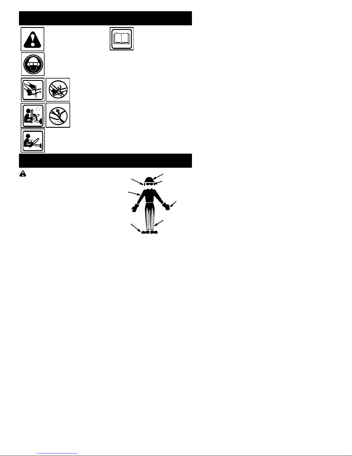
OPERATE YOUR SAW SAFELY
SDonotoperateachainsawwithonehand.
Serious injury to theoperator, helpers, by-
standers or any combination of these per-
sons may result from one-handed opera-
tion. A chain saw is intended for
two-handed use.
SOperatethe chainsaw only in awell-venti-
lated outdoor area.
SDo not operate saw from a ladder or in a
tree.
SMake sure thechain will notmakecontact
with any object while starting the engine.
Never try to start the saw when the guide
bar is in a cut.
SDo not put pressure onthe saw at theend
of the cut. Applying pressure can cause
you to lose control when the cut is com-
pleted.
SStop the engine before setting the saw
down.
SDo not operate a chain saw that is dam-
aged, improperly adjusted, or not com-
pletely and securely assembled. Always
replace bar, chain, hand guard, or chain
brakeimmediately ifit becomesdamaged,
broken or is otherwise removed.
SWith the engine stopped, hand carry the
chain saw with the muffler away from your
body, and the guide bar and chain to the
rear, preferably covered with a scabbard.
MAINTAIN YOUR SAW IN GOOD
WORKINGORDER
SHaveall chainsawserviceperformedbya
qualifiedservice dealerwith the exception
of theitems listed in the maintenance sec-
tionofthis manual. Forexample,ifimprop-
er tools are used toremove or hold the fly-
wheelwhenservicingtheclutch,structural
damage to the flywheel can occur and
cause the flywheel to burst.
SMake certain the saw chain stops moving
when the throttle trigger is released. For
correction, refer to CARBURETOR AD-
JUSTMENTS.
SNever modify your saw in any way.
SKeepthe handlesdry, clean, andfreeof oil
or fuel mixture.
SKeep fuel and oil caps, screws, and fas-
teners securely tightened.
SUse only Snappert/Poulan!accessories
and replacement parts as recommended.
HANDLE FUEL WITH CAUTION
SDo not smoke while handling fuel or while
operating the saw.
SEliminate all sources of sparks or flame in
the areas where fuel is mixed or poured.
Thereshouldbenosmoking,openflames,
orworkthatcouldcausesparks. Allowen-
gine to cool before refueling.
SMix and pour fuel in an outdoor area on
bare ground; store fuel in a cool, dry, well
ventilated place; and use an approved,
marked container for all fuel purposes.
Wipe up all fuel spills before starting saw.
SMove at least 10 feet (3 meters) from fuel-
ing site before starting engine.
STurn the engine off and let saw cool in a
non-combustible area, not on dry leaves,
straw, paper, etc. Slowly remove fuel cap
and refuel unit.
SStoretheunitandfuelinanareawherefuel
vapors cannot reach sparks or open
flames from waterheaters,electric motors
or switches, furnaces, etc.
KICKBACK
WARNING: Avoid kickback which
can result in serious injury. Kickbackis the
backward,upwardorsuddenforwardmotion
of the guide bar occurring when the saw
chainneartheuppertip oftheguidebarcon-
tacts any object such as a log or branch, or
when the wood closes in and pinches the
sawchaininthecut.Contactingaforeignob-
ject in the wood can also result in loss of
chain saw control.
SRotationalKickbackcan occur whenthe
moving chain contacts an object at theup-
per tip of the guide bar. This contact can
cause the chain to dig into the object,
which stops the chain for an instant. The
result is a lightning fast, reverse reaction
which kicks the guide bar up and back to-
ward the operator.
SPinch-Kickbackcan occur when the the
wood closes in and pinches the moving
saw chain in the cut along the top of the
guide bar and the saw chain is suddenly
stopped. This sudden stopping of the
chain results in a reversal of the chain
force used to cut wood and causes the
sawtomoveintheoppositedirectionofthe
chain rotation. The saw is driven straight
back toward the operator.
SPull-In can occur when the moving chain
contacts a foreign object in the wood in the
cut along the bottom of the guide bar and the
saw chainis suddenly stopped. This sudden
stopping pulls the saw forward and away
from the operatorand could easily cause the
operator to lose control of the saw.
Avoid Pinch--Kickback:
SBe extremely aware of situations or ob-
structions thatcan causematerial to pinch
the top of or otherwise stop the chain.
SDo not cut more than one log at a time.
SDo not twist the saw as the bar is with-
drawn from an undercut when bucking.
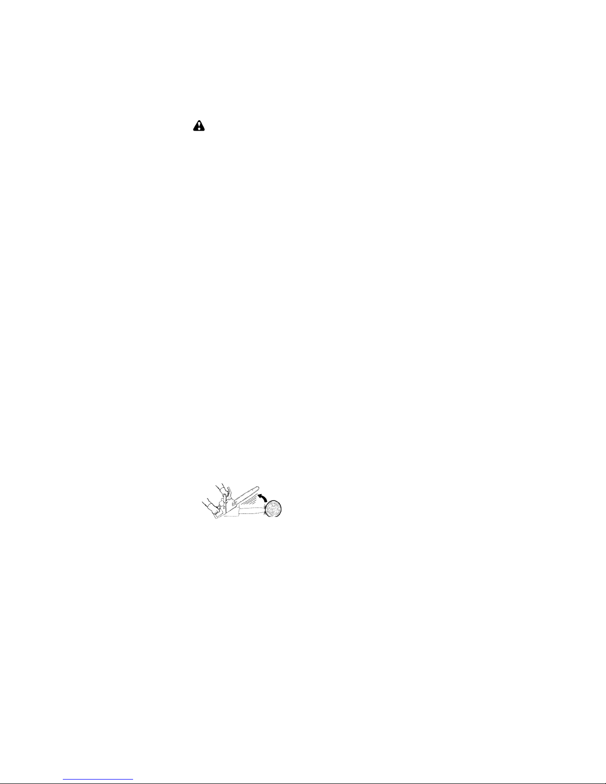
Avoid Pull--In:
SAlways begincutting with theengineatfull
speedandthesawhousingagainst wood.
SUse wedges made of plastic or wood.
Never use metal to hold the cut open.
Kickback Path

4
Avoid Obstructions
Clear The Working Area
REDUCETHE CHANCE OF
KICKBACK
SRecognize that kickback can happen.
With a basic understanding of kickback,
you can reduce the element of surprise
which contributes to accidents.
SNeverletthemovingchaincontactanyob-
ject at the tip of the guide bar.
SKeep the working area free from obstruc-
tionssuchasothertrees,branches,rocks,
fences, stumps, etc. Eliminate or avoid
any obstruction that your saw chain could
hit while you are cutting. When cutting a
branch, do not let the guide bar contact
branch or other objects around it.
SKeep your saw chain sharp and properly
tensioned. A loose or dull chain can in-
crease the chance of kickback occurring.
Follow manufacturer’s chain sharpening
andmaintenanceinstructions. Checkten-
sion at regular intervals with the engine
stopped, never with the engine running.
Make sure the chain brake nuts are se-
curely tightenedaftertensioningthechain.
SBegin andcontinuecuttingatfull speed. If
the chain is moving at a slower speed,
thereis greaterchance ofkickback occur-
ring.
SCut one log at a time.
SUse extreme caution when re-entering a
previous cut.
SDo not attempt cuts starting with the tip of
the bar (plunge cuts).
SWatch for shifting logs or other forces that
could close a cut and pinch or fall into
chain.
SUse the Reduced--Kickback Guide Bar
and Low--Kickback Chain specified for
your saw.
MAINTAIN CONTROL
Never reverse
hand positions
Stand to the
left of the saw
Thumb on
underside of
handlebar
Thumb on underside of
handlebar
Elbow locked
SKeepagood,firmgriponthesawwithboth
hands when the engine is running and
don’tletgo. Afirmgripwill helpyoureduce
kickback and maintain control of the saw.
Keep the fingers of your left hand encir-
cling and your left thumb under the front
handlebar. Keep your right hand com-
pletely around the rear handle whether
yourarerighthandedorlefthanded. Keep
your left arm straight with the elbow
locked.
SPosition yourlefthandonthefronthandle-
bar so it is in a straight line with your right
hand on the rear handle when making
bucking cuts. Never reverse right and left
hand positions for any type of cutting.
SStandwithyourweightevenlybalancedon
both feet.
SStand slightly to the left side of the saw to
keep your body from being in a direct line
with the cutting chain.
SDo not overreach. You could be drawnor
thrown off balance and lose control of the
saw.
SDonotcutaboveshoulderheight. It isdiffi-
cult to maintain control of saw above
shoulder height.
KICKBACKSAFETY FEATURES
WARNING: The following features
are included on your saw to help reduce the
hazard of kickback; however, such features
will not totally eliminate this danger. As a
chainsawuser,donotrelyonlyonsafetyde-
vices. You must follow all safety precau-
tions, instructions, and maintenance in this
manual to help avoid kickback and other
forces which can result in serious injury.
SReduced--Kickback Guide Bar, designed
with a small radius tip which reduces the
size of the kickback danger zone on the
bar tip. A Reduced--Kickback Guide Bar
hasbeendemonstratedto significantly re-
ducethenumberandseriousness ofkick-
backs when tested in accordance with
safety requirements for gasoline powered
chain saws as set by ANSI B175.1.

5
Small Radius Tip
Reduced Kickback Symmetrical Guide Bar
Symmetrical Guide Bar
Large Radius Tip
SLow--Kickback Chain, designed with a
contoured depth gauge and guard link
which deflect kickback force and allow
woodtograduallyrideintothecutter.Low--
Kickback Chain has met kickback per-
formance requirements when tested on a
representative sample of chain saws be-
low 3.8 cubic inch displacement specified
in ANSI B175.1.
Low---Kickback
Chain
Not a Low---Kickback Chain
Can Obstruct Material
Contoured Depth Gauge
Elongated Guard Link
Deflects
kickback force
and allows wood
to gradually ride
into cutter
SFront Hand Guard, designed to reduce the
chance of your left hand contacting thechain
if your hand slips off the front handlebar.
SPosition of front and rear handlebars, de-
signedwithdistancebetweenhandlesand
“in-line” with each other. The spread and
“in-line” position of the hands provided by
this design work together to give balance
and resistance in controlling the pivot of
the saw back toward the operator if kick-
back occurs.
CHAIN BRAKEAND CKA ANGLE
SChain Brake,designedto stopthechainin
the event of kickback.
WARNING: WE DO NOT REP-
RESENT AND YOU SHOULD NOT AS-
SUME THAT THE CHAIN BRAKE WILL
PROTECT YOU IN THE EVENT OF A KICK-
BACK. Kickback is a lightning fast action
which throws the bar and rotating chain back
and up toward the operator. Kickback can be
caused by allowing contact of the bar tip in the
danger zone with any hard object. Kickback
canalsobecausedbypinchingthesawchain
along the top of the guide bar. This actionmay
push the guide bar rapidly back toward theop-
erator. Either of these events may cause you
to lose control of the saw which could result in
serious injury or even death. DO NOT RELY
UPON ANY OF THE DEVICES BUILT INTO
YOUR SAW. YOU SHOULD USE THE SAW
PROPERLY AND CAREFULLY TO AVOID
KICKBACK. Reduced--kickback guide bars
and low--kickback saw chains reduce the
chance and magnitude of kickback and are
recommended. Your saw has a low kickback
chain and bar as original equipment. Repairs
on a chain brake should be made by an autho-
rized servicing dealer. Take your unit to the
place of purchase if purchased from a servic-
ing dealer, or to the nearest authorized master
service dealer.
STipcontactinsomecasesmaycausealight-
ning fast reverse REACTION, kicking guide
bar up and back toward operator.
SPinching the saw chain along the top of the
guide bar may push the guide bar rapidly
back toward the operator.
SEither of these reactions may cause you to
lose control of the saw which could result in
serious injury. Do not rely exclusively upon
devices built into your saw.
WARNING: Computed kickback
angle (CKA) listed on yoursaw andlisted inthe
CKA table below represents angle of kickback
your bar and chain combinations will have
when tested in accordance with CSA (Cana-
dian Standards Association) and ANSI stan-
dards. When purchasing replacement bar and
chain, considerations should be given to the
lower CKA values. Lower CKA values repre-
sent safer angles to the user, higher values in-
dicate more angle and higher kick energies.
Computed angles represented indicate total
energy and angle associated withoutactivation
of the chain brake during kickback. Activated
anglerepresentschain stoppingtime relativeto
activation angle of chain break and resulting
kick angle of saw. In all cases lower CKA val-
ues represent a safer operating environment
for the user.
The following guide bar and chain combina-
tions meet kickback requirements of CSA
Standards Z62.1, Z62.3, & ANSI B175.1
when used on saws listed in this manual.
Use of bar and chain combinations other
than those listed is not recommended and
may not meet the CKA requirements per
standard.
Computed kickback angle (CKA) Table
BAR
P/N Length CHAIN P/N
952044370 16"
MODEL CKA without chain brake
S1634 LE 19_
952051534
S1838 LE 952044418 18"952051535 14_

6
NOTE: If this saw is to be used for com-
mercial logging, a chain brake is required
and shall not be removed or otherwise dis-
abledtocomply withFederalOSHARegula-
tions for Commercial Logging.
SAFETY NOTICE:Exposure to vibrations
through prolonged use of gasoline powered
hand tools could cause blood vessel or nerve
damage in the fingers, hands, and joints of
people prone to circulation disorders or
abnormal swellings. Prolonged use in cold
weather has been linked to blood vessel
damage in otherwise healthy people. If
symptoms occur such as numbness, pain,
loss of strength, changein skin color or texture,
or loss of feeling in the fingers, hands, or joints,
discontinue the use of this tool and seek
medical attention. An anti-vibration system
does not guarantee the avoidance of these
problems. Users who operate power tools on
a continual and regular basis must monitor
closely their physical condition and the
condition of this tool.
SPECIALNOTICE:Yoursawisequipped
with atemperaturelimiting mufflerandspark
arresting screen which meets the
requirements of California Codes 4442 and
4443. All U.S. forest land and the states of
California, Idaho, Maine, Minnesota, New
Jersey, Oregon,andWashington require by
law that many internal combustion engines
tobeequippedwithasparkarrestingscreen.
Ifyouoperateachainsawinastate orlocale
wheresuch regulationsexist, youarelegally
responsible for maintaining the operating
condition of these parts. Failure to do so is
a violation of thelaw. Refer to theSERVICE
section for maintenance of the spark
arresting screen.
FailuretofollowallSafetyRulesandPrecau-
tions canresult in serious injury. If situations
occur which are not covered in this manual,
use care and good judgement. If you need
assistance, contact your authorized service
dealer or call 1-800--554--6723.
STANDARDS: This sawis listedbyUnder-
writer’s Laboratories, Inc., in accordance with:
ANSI B175.1--2000 American National
Standards for Gasoline--Powered Chain
Saws -- Safety Requirements
CSA Z62.1--1995 Chain Saws -- Occupa-
tional Health and Safety
CSA Z62.3--1996 Chain Saw Kickback Oc-
cupational Health and Safety
ASSEMBLY
Protective gloves (not provided) should be
worn during assembly.
ATTACHINGTHEBAR&CHAIN(Ifnot
already attached)
WARNING: If received assembled,
repeat all steps to ensure your saw is properly
assembled and all fasteners are secure. Al-
ways wear gloves when handling the chain.
The chain is sharp andcan cut you even when
it is not moving!
1. Loosen and remove the chain brake
nuts and the chain brake from the saw.
2. Remove the plastic shipping spacer (if
present).
Chain Brake
Chain Brake
Nuts
Bar Tool
Location of shipping space
r
3. An adjusting pin and screw is used to ad-
just the tension of the chain. It is very im-
portant when assembling the bar, that the
pin located on the adjusting screw aligns
into a hole in thebar. Turning thescrew will
move the adjustment pin up anddown the
screw. Locate this adjustment before you
begin mounting the bar onto the saw. See
illustration below.
Adjustment located on Chain Brake
Inside view of
Chain Brake
4. Turn the adjusting screw by hand coun-
terclockwise until the adjusting pin just
touches the stop. This should allow the
pin to be near the correct position.
5. Slide guide bar behind clutch drum until
guide bar stops against clutch drum
sprocket.
Mount the Bar
6. Carefully remove the chainfrom thepack-
age. Hold chain with the drive links as
shown.
CUTTERS MUST FACE IN
DIIRECTION OF ROTATION
Tip of
Bar

7
Cutters Depth Gauge
Drive Links
Place chain onto the s
p
rocket
7. Place chain over and behind clutch, fit-
ting the drive links in the clutch drum
sprocket.
8. Fit bottom of drive links between the
teeth in the sprocket in the nose of the
guide bar.
9. Fit chain drive links into bar groove.
10. Pull guidebar forwarduntil chain is snug
in guide bar groove. Ensure all drive
links are in the bar groove.
NOTE: CHAIN BRAKE MUST BE
DISENGAGED BEFORE INSTALLA-
TIONONTHESAW. TODISENGAGE
CHAIN BRAKE, PULL THE FRONT
HANDGUARDBACKTOWARDTHE
REAR OF THE CHAIN BRAKE AS
FARASPOSSIBLE(SEEILLUSTRA-
TION).
DISENGAGED
ENGAGED
Chain Brake
Front Hand Guard
11. Now, install chainbrakemakingsurethe
adjusting pin is positioned in the lower
holeintheguidebar. Rememberthispin
moves thebarforwardandbackwardas
the screw is turned.
12. Install chain brake nuts and finger tight-
en only. Once the chain is tensioned,
youwill needtotightenchainbrakenuts.
CHAIN TENSION
(Including units with chain already installed)
NOTE: When adjusting chain tension,
make sure the chain brake nuts are finger
tight only. Attempting to tension the chain
when the chain brake nuts are tight can
cause damage.
Checking the tension:
Use thescrewdriver end ofthe chain adjust-
menttool(bartool)tomovethechainaround
the bar. If the chain does not rotate, it is too
tight.Iftooloose, thechainwill sagbelowthe
bar.
Chain Brake Nuts Chain Adjustment
Tool (Bar Tool)
Adjusting the tension:
Chain tension is very important. Chain
stretches during use. This is especially true
during the first few times you use your saw.
Always check chain tension each time you
use and refuel your saw.
You can adjust the chain tension by loosen-
ing the chain brake nuts and turning the ad-
justing screw 1/4of a turn while lifting up on
the bar.
SIfchainistootight,turnadjustingscrew1/4
turn counterclockwise.
SIf chain is too loose, turn adjusting screw
1/4 turn clockwise.
Adjusting
Screw
Chain Brake Nuts Guide Bar
Adjusting Screw -- 1/4 Turn
SLift up the tip of the bar and tighten the
chain brake nuts with the bar tool.
SRecheck chain tension.
Chain Brake
Nuts
WARNING: If the saw is operated
with a loose chain, the chain could jump off
the guide bar and result in serious injury.

8
OPERATION
KNOW YOUR CHAIN SAW
READ THIS INSTRUCTION MANUAL AND SAFETY RULES BEFORE OPERATING YOUR
CHAIN SAW. Compare the illustrations with your unit to familiarize yourself with the location of
the various controls and adjustments. Save this manual for future reference.
Chain
Adjustment Tool
(Bar Tool)
Primer
Bulb
Fuel Mix Fill Cap
Starter
Housing
Bar Oil Fill Cap
Chain
Front Hand Guard Front Handle
Starter Rope
ON/STOP
Switch
Muffler
Guide Bar
Chain Brake
Nuts
Cylinder Cover
Throttle
Lockout
Rear
Handle
Throttle
Trigger Choke
Knob Chain
Brake
Chain
Direction
of Travel
Adjusting
Screw
Chain
Catcher
Fast Idle
Lock
Bar
Sprocket
Hole
ON/STOP SWITCH
The ON/STOP SWITCH is used to stop the
engine.
THROTTLE TRIGGER
The THROTTLE TRIGGER controls engine
speed.
THROTTLE LOCK--OUT
The THROTTLE LOCK--OUT must be
pressed before you can squeeze the throttle
trigger. This feature prevents you from acci-
dentally squeezing the trigger.
FAST IDLE LOCK
TheFAST IDLE LOCK holdsthethrottletrigger
in the starting position. Activate the fast idle
lock by pressing the throttle lockout and
squeezing the throttle trigger. With the throttle
trigger squeezed, press the fast idle lock. Re-
lease thethrottle lockout and trigger while hold-
ing the fast idle lock button.
CHOKE KNOB
The CHOKE KNOB activates the choke to
provide additional fuel to the engine during cold
starting.
PRIMER BULB
The PRIMER BULB circulates fuel to the car-
buretor to provide quicker starting.
CHAIN BRAKE
The CHAIN BRAKE is a device designed to
stop the chain if kickback occurs. The chain
brake activates automatically in the event of
kickback. The chain brake activates manually
if the front hand guard is pushed forward. The
chain brake is disengaged by pulling the front
hand guard back toward the front handle as far
as possible.
CHAIN TENSION
Itisnormal foranewchain tostretchduringfirst
15 minutes of operation. You should check
your chain tension frequently. See CHAIN
TENSION under the ASSEMBLY section.
WARNING: Muffler is very hot dur-
ingandafteruse. Donottouchthemuffleror
allow combustible material such as dry
grass or fuel to do so.

9
FUELING & LUBRICATION
WARNING: Removefuelcapslow-
ly when refueling.
FUELING ENGINE
This engine is certified to operate on un-
leaded gasoline. Before operation, gasoline
must be mixed with a good quality synthetic
2-cycle air-cooled engine oil designed to be
mixedataratioof40:1. SnappertorPoulan/
Weed Eaterrbrand synthetic oil is recom-
mended. Mix gasoline and oil at a ratio of
40:1. A 40:1 ratio is obtained by mixing 3.2
ounces (95 ml) of oil with 1 gallon (4 liters) of
unleadedgasoline. Included withthis saw is
a 3.2 ounce container of oil. Pour the entire
contentsofthiscontainerinto1gallonofgas-
oline to achieve the proper fuel mixture.
DO NOT USE automotive oil or boat oil. These
oils will cause engine damage. When mixing
fuel, follow instructions printed on container.
Once oil is added to gasoline, shake container
momentarily to assure that thefuel is thorough-
ly mixed. Always read and follow the safety
rules relating to fuel before fueling your unit.
BAR AND CHAIN LUBRICATION
The bar and chain require continuous lubri-
cation. Lubrication is provided by the auto-
matic oiler system when the oil tank is kept
filled. Lack of oil will quickly ruin the bar and
chain. Too little oil will cause overheating
shownby smokecomingfromthechainand/
or discoloration of the bar.
In freezing weather oil will thicken, makingit
necessary to thin bar and chain oil with a
small amount(5to10%) of#1Diesel Fuel or
kerosene. Bar and chain oil must be free
flowing fortheoil system topumpenoughoil
for adequatelubrication.
GenuineSnappertbar and chain oil is recom-
mended to protect your unit against excessive
wear from heat and friction. Snappertoil re-
sists high temperature thinning.
If Snappertbar and chain oil is not available,
use a good grade SAE 30 oil.
SNeverusewasteoilforbarandchainlubri-
cation.
SAlways stop the engine before removing
the oil cap.
IMPORTANT
Experience indicates that alcohol--blended
fuels (called gasohol or using ethanol or
methanol) can attract moisture which leads
to separation and formation of acids during
storage. Acidic gas can damage the fuel
system of an engine while in storage. To
avoid engine problems, the fuel system
should be emptied before storage for 30
days or longer. Drain the gas tank, start the
engine and let it run until the fuel lines and
carburetor are empty. Use fresh fuel next
season. See STORAGE section for addi-
tional information.
STARTING
WARNING: The chain must not
move when the engineruns at idle speed. If
the chain moves at idle speed refer to CAR-
BURETOR ADJUSTMENT within this
manual. Avoid contact with the muffler. A hot
muffler can cause serious burns.
To stop the engine move the ON/STOP
switch to the STOP position.
To start the engine hold the saw firmly on
the ground as illustrated. Make sure the
chain is free to turn without contacting any
object.
Hold saw firmly while pulling starter rope.
Use only 15”--18” of rope per pull.
Left hand
on front
handle
Right foot through rear handle
Starter rope handle
IMPORTANT POINTS TOREMEMBER
Whenpulling thestarterrope,do not use the
full extent of the rope as this can cause the
rope to break. Do not let starter rope snap
back. Hold the handle and let the rope re-
wind slowly.
NOTE: Do not attempt to cut material with
thefastidlelockbuttoninthelockedposition.
STARTING A COLD ENGINE (or
warm engine after running out of
fuel) ON/STOP SWITCH
ON
STOP
(SIDE VIEW)
1. Move ON/STOP switch to the ON posi-
tion.
2. Pull choke knob out to the full extent.
3. Slowly press primer bulb 6 times.
4. Squeeze and hold throttle trigger. With
thumbpressfastidle lock down;thenre-
lease throttle trigger.
Fast idle lock button
Choke knob
Throttle
trigger
Throttle
lock--out
5. Sharply pull the starter rope handle 5
times with your right hand. Then, pro-
ceed to the next step.

10
NOTE: If the engine sounds as if it is try-
ing to start beforethe 5th pull, stop pulling
and immediately proceed to the next step.
6. Push the choke knob in completely (to
the OFF position); pull the starter rope
until the engine starts.
OFF FULL
CHOKE
Choke knob
(SIDE VIEW)
7. Allow theenginetorun forapproximate-
ly 5 seconds. Then, squeeze and re-
lease throttle trigger to allow engine to
return to idle speed.
STARTING A WARM ENGINE:
1. Move ON/STOP switch to the ON posi-
tion.
2. Push the choke knob in completely (to
the OFF position).
3. Slowly press primer bulb 6 times.
4. Squeeze and hold throttle trigger. With
thumbpressfastidle lock down;thenre-
lease throttle trigger.
5. Sharply pull the starter rope with your
right hand until the engine starts.
6. Squeeze and release throttle trigger to
allow engine to return to idle speed.
DIFFICULT STARTING (or starting a
flooded engine):
The engine may be flooded with too much
fuel if it has not started after 10 pulls.
Flooded engines can be cleared of excess
fuel by following the warm engine starting
procedure listed above. Insure the ON/
STOP switch is in the ON position.
Startingcouldrequirepullingthestarterrope
handle many times dependingon howbadly
theunitis flooded.Ifenginefailstostart,refer
to the TROUBLESHOOTING TABLE or call
1-800-554-6723.
CHAIN BRAKE
WARNING: If the brake band is
worn too thin it may break when the chain
brakeistriggered.Withabrokenbrakeband,
the chain brake will not stop the chain. The
chain brakeshouldbereplacedby an autho-
rized service dealerif anypartis worntoless
than 0.020"(0.5 mm) thick. Repairs on a
chain brake should be made by an autho-
rized service dealer. Take your unit to the
place of purchase if purchased from a ser-
vicing dealer, or to the nearest authorized
master service dealer.
SThis saw is equipped with a chain brake.
The brake is designed to stop the chain if
kickback occurs.
SThe inertia--activated chain brake is
activated if the front hand guard is pushed
forward, either manually (by hand) or
automatically (by sudden movement).
SIf the brake is already activated, it is
disengagedbypullingthefronthandguard
back toward the front handle as far as
possible.
SWhencuttingwiththesaw,thechainbrake
must be disengaged.
Disengaged
Engaged
Braking function control
CAUTION: The chain brake must be
checked several times daily. The engine
mustberunningwhenperformingthisproce-
dure. This is theonly instancewhenthe saw
should be placed on the ground with the en-
gine running.
Place the saw on firm ground. Grip the rear
handlewithyourrighthandandthefronthan-
dle with your left hand. Apply full throttle by
fully depressing the throttle trigger. Activate
the chain brake by turning your left wrist
against the hand guard without releasing
your grip around the front handle. The chain
should stop immediately.
Inertia activating function control
WARNING: When performing the
following procedure, the engine must be
turned off.
Grip therearhandlewithyourright handand
the fronthandlewith your left hand. Holdthe
chainsawapproximately14"(35cm)above
a stump or other wooden surface. Release
your grip on the front handle and use the
weight of the saw to let the top of the guide
bar fall forward and contact the stump.
When the tip of the bar hits the stump, the
brake should activate.
CUTTING METHODS
IMPORTANT POINTS
SCheck chain tension before first use and
after 1 minute of operation. See CHAIN
TENSION in the ASSEMBLY section.
SCut wood only. Do not cut metal, plastics,
masonry, non-wood building materials, etc.
SStop the saw if the chain strikes a foreign
object. Inspect the saw and repair or re-
place parts as necessary.
SKeep the chain out of dirt and sand. Even a
small amount of dirt will quickly dull a chain
andthusincreasethe possibility ofkickback.
SPractice cutting a few small logs using the
followingtechniques togetthe“feel” ofus-
ing your saw before you begin a major
sawing operation.
SSqueeze the throttle trigger and allow
the engine to reach full speed before
cutting.
SBegin cutting with the saw frame
against the log.
SKeeptheengineatfull speedtheentire
time you are cutting.

11
SAllowthechaintocutforyou.Exertonly
light downward pressure. If you force
thecut,damagetothebar,chain,oren-
gine can result.
SRelease the throttle trigger as soonas
the cut is completed, allowing the en-
gine to idle. If you run the saw at full
throttlewithoutacuttingload,unneces-
sary wear can occur to the chain, bar,
and engine. It is recommended that
the engine not be operated for lon-
ger than 30 seconds at full throttle.
SToavoidlosingcontrolwhencutiscom-
plete,donotputpressureonsawatend
of cut.
SStop the engine before setting the saw
down after cutting.
TREE FELLING TECHNIQUES
WARNING: Check for broken or
dead branches which can fall while cutting
causingseriousinjury. Donotcutnearbuild-
ings or electrical wires if you donot knowthe
directionoftreefall,norcutatnightsinceyou
will not be ale to see well, nor during bad
weathersuchasrain,snow,orstrongwinds,
etc. If thetreemakes contactwith any utility
line, the utility company should be notified
immediately.
SCarefullyplanyoursawingoperationinad-
vance.
SCleartheworkarea. Youneedacleararea
all aroundthetreeso you canhavesecure
footing.
SThe chain saw operator should keep on
the uphill side of the terrain as the tree is
likely toroll orslidedownhill afterit isfelled.
SStudy the natural conditions that can cause
thetreetofallinaparticulardirection.
Natural conditions that can cause a tree to
fall in a particular direction include:
SThe wind direction and speed.
SThe lean of the tree. The lean of a tree
might not be apparent due to uneven or
sloping terrain. Useaplumb orlevel tode-
termine the direction of tree lean.
SWeight and branches on one side.
SSurroundingtrees and obstacles.
Look for decay and rot. If thetrunk is rotted,
it can snap and fall toward the operator.
Check for broken or dead branches which
can fall on you while cutting.
Make sure there is enough roomfor thetree
to fall. Maintain a distance of 2-1/2 tree
lengths from the nearest person or otherob-
jects. Enginenoisecandrownoutawarning
call.
Remove dirt, stones, loose bark, nails, sta-
ples,andwirefromthetreewherecutsareto
be made.
Plana clearretreatpathtotherearanddiag-
onal to the line of fall.
Direction of Fall
45_
Plan a clear retreat path
FELLING LARGE TREES
(6 inches in diameter or larger)
The notch method is used to fell large trees.
Anotchis cut ontheside ofthetreein thede-
sired direction of fall. After a felling cut is
made on the opposite side of tree, the tree
will tend to fall into the notch.
NOTE: If the tree has large buttress
roots, remove them before making the
notch. If using saw to remove buttress
roots, keep saw chain from contacting
ground to prevent dulling of the chain.
NOTCH CUT AND FELLING THE
TREE
SMake notch cut by cutting the top of the
notch first. Cut through 1/3 of thediameter
ofthetree.Nextcompletethenotchbycut-
ting the bottom of the notch. See illustra-
tion. Once the notch is cut remove the
notch of wood from the tree.
Notch
First cut
Second cut
Final (felling) cut here. 2 in-
ches above center of notch.
Hinge
SAfter removing the wood from the notch,
make the felling cut on the opposite side of
thenotch.This isdoneby makingacutabout
two inches higher than the center of the
notch. This will leave enough uncut wood
between the felling cut and the notch to form
a hinge. This hinge will help prevent the tree
from falling in the wrong direction.
Opening
of felling
cut
Closing of
notch
Hinge holds tree on stump and helps
control fall

12
NOTE: Before felling cut is complete, use
wedges to open the cut if necessary to
controlthedirectionoffall. Toavoidkickback
and chain damage, use wood or plastic
wedges, but never steel or iron wedges.
SBe alert to signs that the tree is ready to
fall: cracking sounds, widening of the fell-
ing cut, or movement in the upper
branches.
SAs tree starts to fall, stop saw, put it down,
and get away quickly on your planned re-
treat path.
SDO NOT cut down a partially fallen tree
with your saw. Beextremely cautiouswith
partially fallen trees that may be poorly
supported. When a tree doesn’t fall com-
pletely,setthesawasideandpulldownthe
tree with a cable winch, block and tackle,
or tractor.
CUTTING A FALLEN TREE
(BUCKING)
Bucking is the term used for cutting a fallen
tree to the desired log size.
WARNING: Donotstandon thelog
being cut. Any portion can roll causing loss
of footing and control. Do not stand downhill
of the log being cut.
IMPORTANT POINTS
SCut only one log at a time.
SCut shattered wood very carefully; sharp
pieces of wood could be flung toward opera-
tor.
SUse a sawhorse to cut small logs. Never
allow another person to hold the log while
cuttingandneverholdthelogwith yourleg
or foot.
SDo not cut in an area where logs, limbs,
and roots are tangled such as in a blown
down area. Dragthe logs into a clear area
before cutting by pulling out exposed and
cleared logs first.
TYPES OF CUTTING USED FOR
BUCKING
WARNING: If saw becomes
pinched or hung in a log, don’t try to force it
out. Youcanlosecontrolofthesawresulting
in injury and/ordamageto thesaw. Stopthe
saw,drive awedgeofplasticorwoodintothe
cut until thesaw canbe removedeasily. Re-
startthesawandcarefullyreenterthecut. To
avoid kickback and chain damage, do not
useametalwedge. Donotattempttorestart
your saw whenit is pinchedor hungin a log.
Use a wedge to remove pinchedsaw
Turn saw OFF and use a plastic or
wooden wedge to force cut open.
Overcutting begins on the top side of the log
with the bottom of the saw against the log.
When overcutting use light downward pres-
sure.
Overcutting
Undercutting
Undercuttinginvolves cutting ontheunder-
side ofthelogwithtopofsawagainstthelog.
When undercutting use light upward pres-
sure. Hold saw firmly and maintain control.
The saw will tend to push back toward you.
WARNING: Never turn saw upside
down to undercut. The saw cannot be con-
trolled in this position.
Always make your first cut on the compres-
sion sideofthelog. Thecompressionsideof
the log is where the pressure of the log’s
weight is concentrated.
Second cut
First cut on compression side of log
Second cut
BUCKINGWITHOUT A SUPPORT
SOvercut through 1/3 of the diameter of the
log.
SRoll the log over and finish with a second
overcut.
SWatch for logs with a compression side to
prevent the saw from pinching. See il-
lustrations forcutting logs with acompres-
sion side.
BUCKINGUSING A LOG OR
SUPPORT STAND
SRemember your first cut is always on the
compression side of the log.
(Refer to the illustrations below for your
first and second cut)
SYour first cut should extend 1/3 of the
diameter of the log.
SFinish with your second cut.
1st Cut
2nd Cut
Using a log for support

13
2nd Cut
1st Cut
1st Cut
2nd Cut
Using a support stand
1st Cut
2nd Cut
LIMBING AND PRUNING
WARNING: Be alert for and guard
against kickback. Do not allow the moving
chain to contact any other branches or objects
at the nose of the guide bar when limbing or
pruning. Allowing such contact can result in
serious injury.
WARNING: Never climbintoatreeto
limb or prune. Do not stand on ladders, plat-
forms, a log, or in any position which can cause
you to lose your balance or control of the saw.
IMPORTANT POINTS
SWork slowly, keeping both hands firmly
gripped on the saw. Maintain secure footing
and balance.
SWatch out for springpoles. Springpoles are
small size limbs which can catch the saw
chain and whip towardyouor pull youoffbal-
ance. Use extreme caution when cutting
small size limbs or slender material.
SBe alert for springback. Watch out for
branches that are bent or under pressure.
Avoid being struck by the branch or the
saw when thetension in the woodfibers is
released.
SKeep a clear work area. Frequently clear
branches out of the way to avoid tripping
over them.
LIMBING
SAlwayslimbatreeafteritiscutdown. Only
then can limbing be donesafely and prop-
erly.
SLeave the larger limbs underneath the felled
tree to support the tree as you work.
SStart at the base of the felled tree and work
toward the top, cutting branches and limbs.
Remove small limbs with one cut.
SKeepthetreebetweenyouandthechain.
Cut from the side of the tree opposite the
branch you are cutting.
SRemove larger, supporting branches with
the cutting techniques described in BUCK-
ING WITHOUT A SUPPORT.
SAlways use an overcutto cut small and free-
ly hanging limbs. Undercutting could cause
limbs to fall and pinch the saw.
PRUNING
WARNING: Limit pruning to limbs
shoulder height or below. Do not cut if
branches are higher than your shoulder. Get a
professional to do the job.
SMakeyour firstcut1/3 oftheway throughthe
bottom of the limb.
SNext make a 2nd cut all the way through
thelimb. Thencutathirdovercutleavinga
1 to 2 inch collar from the truck of the tree.
First cut
Second cut
Third cut
Collar
Pruning technique
SERVICE
WARNING: Disconnect the spark
plug before performing maintenance except
for carburetor adjustments.
We recommend all service andadjustments
not listed in this manual be performedby an
authorized or Master Service Dealer.
MAINTENANCE SCHEDULE
Check:
Fuel mixture level Before each use....
Bar lubrication Before each use.......
Chain tension Before each use.......
Chain sharpness Before each use....
For damaged parts Before each use..
For loose caps Before each use......
For loose fasteners Before each use...
For loose parts Before each use......
Inspect and Clean:
Bar Before each use................
Complete saw After each use.......
Air filter Every 5 hours*.............
Chain brake Every 5 hours*........
Spark arresting screen
and muffler Every 25 hours*.........
Replace spark plug Yearly.
Replace fuel filter Yea rly...
* Hours of Operation

14
AIR FILTER
CAUTION:Do not clean filter in gasoline
or other flammable solvent to avoid creating
a fire hazard or producing harmful evapora-
tive emissions.
Cleaning the air filter:
A dirty air filter decreases engine perform-
ance and increases fuel consumption and
harmful emissions. Always cleanafterevery
5 hours of operation.
1. Loosen 3 screws on cylinder cover.
2. Remove cylinder cover.
3. Remove air filter.
4. Cleantheairfilter usinghotsoapywater.
Rinse with clean cool water. Air dry
completely before reinstalling.
5. Lightly oil air filter beforeinstalling toim-
prove the efficiency of air filter. Use
2--cycle engine oil ormotoroil (SAE30).
Squeeze excess oil from filter.
6. Reinstall air filter.
7. Reinstall cylinder cover and 3 screws.
TIghten securely.
Air Filter Cylinder Cover
Screws
Cylinder
Cover
INSPECT MUFFLER AND SPARK
ARRESTINGSCREEN
WARNING: The muffler on this
product contains chemicals known to the
State of California to cause cancer.
As theunit is used, carbondeposits buildup
on the muffler and spark arresting screen,
andmustberemovedto avoidcreatingafire
hazard or affecting engine performance.
Replacethesparkarrestingscreenifbreaks
occur.
CLEANING THE SPARK ARREST-
ING SCREEN
Cleaning is required every 25 hours of op-
eration or annually, whichever comes first.
Muffler
Gasket
Muffler
Bolts
Muffler
Locknut
Outlet
Guide
Bolt Cover
Backplate
1. Loosenandremovethelocknutfromthe
bolt cover.
2. Remove the bolt cover.
3. Loosen and remove the 2 muffler bolts.
Removethemuffler,mufflergasket,out-
let guide and backplate. Notice the ori-
entationofthesepartsforreassembling.
4. Locate the 2 outlet cover screws on the
muffler. Loosen and remove both
screws.
5. Remove the outlet cover.
BACK VIEW OF
MUFFLER
Muffler
Spark Arresting
Screen
Outlet Cover
Screws
6. Remove spark arresting screen.
7. Clean the spark arresting screen with a
wire brush. Replace screen if any wires
arebrokenorscreenisblockedafterclea-
ning.
8. Reinstall spark arresting screen.
9. Reinstalloutletcoverand2screws. En-
sure outlet cover and both screws are
reinstalled correctly (see illustrations)to
prevent damage to the saw. The ex-
haust outlet must face the chain brake
(bar side) of the saw.
Exhaust Outlet must face chain
brake (bar side) of chain saw
Outlet Cover
Exhaust
Outlet
10. Inspect themuffler gasket andreplace if
damaged.
11. Reinstall backplate,outlet guide,muffler
gasket, and muffler using muffler bolts.
Tighten until secure.
12. Reinstallboltcoverandlocknut. Tighten
securely.
CARBURETOR ADJUSTMENT
WARNING: Thechain will bemov-
ing duringmostofthisprocedure.Wearyour
protective equipment and observe all safety
precautions.Thechainmustnotmoveatidle
speed.
The carburetorhas beencarefully set at the
factory. Adjustments may be necessary if
you notice any of the following conditions:
SChain moves at idle. See IDLE SPEED--T
adjusting procedure.
SSawwill notidle. SeeIDLESPEED--T ad-
justing procedure.
Idle Speed--T
Allow engineto idle. If the chain moves, idle
is toofast. If theenginestalls, idleis tooslow.
Adjust speed until engine runs without chain
movement (idle too fast) or stalling (idle too
slow). Theidle speedscrew is located in the
area above the primer bulb and is labeled T.

15
STurn idle speed screw (T) clockwise to in-
crease engine speed.
STurn idle speed screw (T) counterclock-
wise to decrease engine speed.
If you require further assistance or are unsure
about performing this procedure, contact your
authorized service dealer or call
1--800--554--6723.
BAR MAINTENANCE
If your saw cutsto oneside, hasto beforced
throughthecut,orbeenrunwithanimproper
amount of bar lubrication it may be neces-
sarytoserviceyourbar. Awornbarwilldam-
age your chain and make cutting difficult.
After each use, ensure ON/STOP switch is
in theSTOP position, thenclean all sawdust
from the guide bar and sprocket hole.
To maintain guide bar:
SMove ON/STOP switch to the STOP posi-
tion.
SLoosen andremovechain brake nuts and
chain brake. Remove bar and chain from
saw.
SClean the oil holes and bar groove after
each 5 hours of operation.
Remove Sawdust From
Guide Bar Groove
Oil Holes
SBurring of guide bar rails is a normal
process of rail wear. Remove these burrs
with a flat file.
SWhenrail topis uneven,usea flatfile tore-
store square edges and sides.
Correct GrooveWorn Groove
File Rail Edges
and Sides
Square
Replace guide bar when the groove is worn,
the guide bar is bent or cracked, or whenexce-
ss heating or burring of the rails occurs. If re-
placement is necessary, use only the guide bar
specified for your saw in the repair parts list or
onthedecallocatedonthechainsaw.
CHAIN SHARPENING
Chain sharpening is acomplicated task that
requires special tools. We recommended
you refer chain sharpening to aprofessional
chain sharpener.
IGNITION TIMING
Ignition timing is fixed and nonadjustable.
SPARK PLUG
The spark plug should be replaced each
year to ensure the engine starts easier and
runs better.
1. Loosen 3 screws on cylinder cover.
2. Remove the cylinder cover.
3. Pull off the spark plug boot.
4. Remove spark plug from cylinder and
discard.
5. Replace with Champion RCJ--7Y spark
plug andtighten securely with a 3/4inch
socket wrench. Spark plug gap should
be 0.025 inches.
6. Reinstall the spark plug boot.
7. Reinstall the cylinder cover and 3
screws. Tighten securely.
Screws
Spark
Plug Boot
Spark
Plug
Cylinder
Cover
STORAGE
WARNING: Stop engine and allow
to cool, and secure the unit before storing or
transporting in a vehicle. Store unit and fuel
in an area where fuel vapors cannot reach
sparks or open flames from water heaters,
electric motors or switches, furnaces, etc.
Storeunitwithallguardsinplace.Positionso
that any sharp object cannot accidentally
cause injury to passersby. Store the unitout
of reach of children.
SBefore storing, drain all fuel from the unit.
Start engine and allow to run until it stops.
SClean the unit before storing. Pay particu-
lar attention tothe air intake area,keeping
it free of debris. Use a mild detergentand
sponge to clean the plastic surfaces.
SDonotstoretheunitorfuel inaclosedarea
where fuel vapors can reach sparks or an
openflamefromhotwaterheaters,electric
motors or switches, furnaces, etc.
SStore in a dry area out of the reach of chil-
dren.
CAUTION:It is important to prevent gum
deposits from forming in essential fuel system
parts such as the carburetor, fuel filter, fuel
hose, or fuel tank during storage. Alcohol
blended fuels (called gasohol or using ethanol
or methanol) can attract moisture which leads
to fuel mixture separation and formation of
acids during storage. Acidic gas can damage
the engine.
NEED ASSISTANCE?
NEED ASSISTANCE?
Call 1--800--554--6723.
NEED SERVICE PART?
Contact your dealer or place of purchase.

16
TROUBLE CAUSE REMEDY
Engine will not
start or will run
only a few
seconds after
starting.
1. Ignition switch off.
2. Engine flooded.
3. Fuel tank empty.
4. Spark plug not firing.
5. Fuel not reaching
carburetor.
1. Move ignition switch to ON.
2. See “Difficult Starting” in
Operation Section.
3. Fill tank with correct fuel mixture.
4. Install new spark plug.
5. Check for dirty fuel filter; replace.
Check for kinked or split fuel line;
repair or replace.
Engine will
not idle
properly.
1. Idle speed requires
adjustment.
2. Carburetorrequires
adjustment.
1. See “Carburetor Adjustment” in the
Service and Adjustments Section.
2. Contact an authorized service dealer.
1. Air filter dirty.
2. Spark plug fouled.
3. Chain brake engaged.
4. Carburetorrequires
adjustment.
Engine will not
accelerate,
lacks power,
or dies under
a load.
1. Clean or replace air filter.
2. Clean or replace plug and regap.
3. Disengage chain brake.
4. Contact an authorized service dealer.
Engine
smokes
excessively.
1. Too much oil mixed with
gasoline. 1. Empty fuel tank and refill with
correct fuel mixture.
WARNING: Always stop unit and disconnect spark plug before performing all of
therecommendedremediesbelowexceptremedies thatrequireoperationof theunit.
TR
O
UBLE
S
H
O
O
TIN
G
TABLE
Chain moves
at idle speed. 1. Idle speed requires
adjustment.
2. Clutch requires repair.
1. See “Carburetor Adjustment” in the
Service and Adjustments Section.
2. Contact an authorized service dealer.
LIMITED WARRANTY
ELECTROLUX HOME PRODUCTS, INC.,
warrants to the original purchaser that each
new Snappert
tt
tbrand gasoline chain saw is
free from defects in material and workman-
ship and agrees to repair or replace under
this warranty any defective gasoline chain
saw as follows from the original date of pur-
chase.
1 YEAR -- Parts and Labor, when used for
Household purposes.
60 DAYS -- Parts and Labor, when used for
Commercial, Professional, or Income Pro-
ducing purposes.
30DAYS-- PartsandLabor,ifusedforrental
purposes.
This warranty is not transferable and does
not cover damage or liability caused by im-
proper handling, improper maintenance, or
the use of accessories and/or attachments
not specifically recommended by ELEC-
TROLUXHOMEPRODUCTS,INC.,forthis
chain saw. Additionally, this warranty does
not cover damage caused by improper han-
dling, improper maintenance, or if the saw is
alteredinanywaywhichinourjudgementaf-
fectsits conditionoroperation.Thiswarranty
does not cover tune--up, spark plugs, filters,
starterropes,startersprings,chainsharpen-
ing,bars,chains,andotherpartswhichwear
and require replacement with reasonable
useduringthewarrantyperiod.Thiswarran-
ty does not cover predelivery set--up,instal-
lation ofguidebarandchain,andnormalad-
justments explained in the instruction
manual such as carburetoradjustments and
chain tension adjustments. This warranty
does not cover transportationcosts.
THIS WARRANTY GIVES YOU SPECIFIC
LEGAL RIGHTS, AND YOU MAY HAVE
OTHER RIGHTS WHICH VARY FROM
STATE TO STATE.
NO CLAIMS FOR CONSEQUENTIAL OR
OTHER DAMAGES WILL BE ALLOWED,
AND THERE ARE NO OTHER EXPRESS
WARRANTIES EXCEPT THOSE EX-
PRESSLY STIPULATED HEREIN.
SOME STATES DO NOT ALLOW LIMITA-
TIONSONHOW LONGANIMPLIEDWAR-
RANTY LASTS OR THE EXCLUSION OR
LIMITATIONS OF INCIDENTAL OR CON-
SEQUENTIAL DAMAGES, SO THE
ABOVE LIMITATIONS OR EXCLUSION
MAY NOT APPLY TO YOU.
The policy of ELECTROLUX HOME PRO-
DUCTS, INC.,is tocontinuously improveits
products.Therefore,ELECTROLUXHOME
PRODUCTS, INC., reserves the right to
change, modify, or discontinue models, de-
signs, specifications, and accessories of all
productsatanytimewithoutnoticeor obliga-
tion to any purchaser.

17
U.S. EPA/CALIFORNIA/ENVIRONMENT CANADA
EMISSION CONTROL WARRANTY STATEMENT
YOUR WARRANTY RIGHTS AND OBLIGA-
TIONS: The U.S. Environmental Protection
Agency, California Air Resources Board, Envi-
ronment Canada and ELECTROLUX HOME
PRODUCTS, INC., are pleased to explain the
emissions control system warranty on your
year 2002--2004 small off--road engine. InCali-
fornia, all new small off--road engines must be
designed, built, and equipped to meet the
State’s stringent anti--smog standards. ELEC-
TROLUX HOME PRODUCTS, INC., must
warrant the emission control system on your
small off--road engine for the periods of time
listed below provided there has been no abuse,
neglect, or improper maintenance of yoursmall
off--road engine engine. Your emission control
system includes parts such as the carburetor
and the ignition system. Where a warrantable
condition exists, ELECTROLUX HOME
PRODUCTS, INC., will repair your small off--
road engine engine at no cost to you. Ex-
penses covered under warranty include diag-
nosis, parts and labor. MANUFACTURER’S
WARRANTY COVERAGE: If any emissions
related part on your engine (as listed under
Emissions Control Warranty Parts List) is de-
fectiveor adefect inthematerials or workman-
ship of theengine causes the failure of such an
emission related part, the part will be repaired
or replaced by ELECTROLUX HOME PROD-
UCTS, INC. OWNER’S WARRANTY RE-
SPONSIBILITIES: Asthesmalloff--roaden-
gine engine owner, you are responsible for the
performance of the required maintenance
listed in your instruction manual. ELECTRO-
LUX HOME PRODUCTS, INC., recommends
that you retain all receipts covering mainte-
nance on your small off--road engine, but
ELECTROLUX HOME PRODUCTS, INC.,
cannot deny warranty solely for the lack of re-
ceipts or for your failure to ensure the perfor-
mance of all scheduled maintenance. As the
small off--road engine engine owner, you
should be aware that ELECTROLUX HOME
PRODUCTS, INC., may deny you warranty
coverage if your small off--road engine engine
or a part of it has failed due to abuse, neglect,
improper maintenance, unapproved modifica-
tions, or the use of parts not made or approved
by the original equipment manufacturer. You
are responsible for presenting your small off--
road engine to an ELECTROLUX HOME
PRODUCTS,INC.,authorizedrepaircenteras
soon as a problem exists. Warranty repairs
should be completed in a reasonable amount
of time, not to exceed 30 days. If you have any
questions regarding your warranty rights and
responsibilities, you should contact your near-
est authorized service center or call ELEC-
TROLUX HOME PRODUCTS, INC., at
1--800--554--6723. WARRANTY COM-
MENCEMENT DATE: The warranty period
begins on the date the small off--road engine is
purchased. LENGTH OF COVERAGE: This
warranty shall befor aperiod of two years from
the initial date of purchase. WHAT IS COV-
ERED: REPAIR OR REPLACEMENT OF
PARTS. Repair or replacement of any war-
ranted part will be performed at no charge to
the owner at an approved ELECTROLUX
HOME PRODUCTS, INC., servicing center. If
you have any questions regarding your war-
ranty rights and responsibilities, you should
contact your nearest authorized service center
or call ELECTROLUX HOME PRODUCTS,
INC., at 1--800--554--6723. WARRANTY PE-
RIOD: Any warranted part which is not sched-
uled for replacement as required maintenance,
or which is scheduled only for regular inspec-
tion to the effect of “repair or replace as neces-
sary” shall be warranted for 2 years. Any war-
ranted part which is scheduled for replacement
asrequiredmaintenance shall be warrantedfor
theperiodoftimeuptothefirstscheduledre-
placement point for that part. DIAGNOSIS:
The owner shall not be charged for diagnostic
labor which leads to the determination that a
warranted part is defective if the diagnostic
work is performed at an approved ELECTRO-
LUX HOME PRODUCTS, INC., servicing
center. CONSEQUENTIAL DAMAGES:
ELECTROLUX HOME PRODUCTS, INC.,
may be liable for damages to other engine
components caused by the failure of a war-
ranted part still under warranty. WHAT ISNOT
COVERED: All failures caused by abuse, ne-
glect, or improper maintenance are not cov-
ered. ADD--ON OR MODIFIED PARTS: The
use of add--on or modified parts can be
grounds for disallowing a warranty claim.
ELECTROLUX HOME PRODUCTS, INC., is
not liable to cover failures of warranted parts
caused by the use of add--on or modified parts.
HOW TO FILE A CLAIM: If you have any
questions regarding your warranty rights and
responsibilities, you should contact your near-
est authorized service center or call ELEC-
TROLUX HOME PRODUCTS, INC., at
1--800--554--6723. WHERE TO GET WAR-
RANTY SERVICE: Warranty services or re-
pairs shall be provided at all ELECTROLUX
HOME PRODUCTS, INC., service centers.
Call: 1--800--554--6723 MAINTENANCE, RE-
PLACEMENT AND REPAIR OF EMISSION
RELATED PARTS: Any ELECTROLUX
HOME PRODUCTS, INC., approved replace-
ment part used in the performance of any war-
ranty maintenance or repair on emission re-
lated parts will be provided without charge to
the owner if the part is under warranty. EMIS-
SION CONTROL WARRANTY PARTS LIST:
Carburetor, Ignition System: Spark Plug (cov-
ered up to maintenance schedule), Ignition
Module, Muffler including catalyst. MAINTE-
NANCE STATEMENT:Theownerisresponsi-
ble for the performance of all required mainte-
nance as defined in the instruction manual.

18
The information on the product label indicates which standard your engine is certified.
Example: (Year) EPA Phase 1 or Phase 2 and/or CALIFORNIA.
This engine is certified to be emissions compliant for the following use:
Moderate (50 hours)
Intermediate (125 hours)
Extended (300 hours)
Table of contents
Other Snapper Chainsaw manuals