SnapTV 360GBPX Combo User guide

SYSTEM INSTALLATION GUIDE
Version 1.0
September 14, 2012

Contents
1 Introduction 1
1.1 Applicability ...................................... 1
1.2 Target audience .................................... 1
2 Getting started 3
2.1 First time power up .................................. 3
2.2 Console login ..................................... 3
2.3 Setting new passwords ................................ 4
2.4 Setting keyboard mapping .............................. 4
2.5 Network configuration ................................. 5
2.6 Assigning hostname .................................. 8
3 Accessing the web interface 9
3.1 Getting started continued ............................... 9
4 Manage inputs 11
4.1 Numbering of the input sources ........................... 11
4.2 Satellite connection .................................. 11
4.3 Terrestrial connection ................................. 12
4.4 CA modules ...................................... 12
4.5 Analog sources .................................... 12
4.6 List inputs ....................................... 12
5 Manage live signals 15
5.1 List and edit channels ................................. 15
5.2 Add channel from input ................................ 18
5.3 Stream full transport stream from input ....................... 21
5.4 New external multicast ................................ 21
5.5 New looped file channel ................................ 22
6 Manage content 23
6.1 VoD ........................................... 23
6.2 Transcoding DVDs to transport streams ....................... 23
6.3 Mini Browser Pages .................................. 27
i

7 Manage recording 29
7.1 Configure recording of TV and Radio channels ................... 29
7.2 Configure Recorder Manager ............................. 30
8 Content Provisioning Server 33
9 Client provisioning 35
9.1 Amino .......................................... 35
9.2 Standard ........................................ 36
10 System configuration 39
10.1 Network ......................................... 39
10.2 Cluster ......................................... 43
10.3 Mini browser server .................................. 44
10.4 EPG service ...................................... 45
10.5 Monitoring ....................................... 47
10.6 Portal .......................................... 50
10.7 Set time zone ..................................... 53
10.8 Unicast radio services ................................. 53
10.9 Audio Media Player .................................. 54
10.10Manage administrators ................................ 54
10.11Configuration profiles ................................. 56
10.12Setting up SSL ..................................... 57
11 System information 59
11.1 License ......................................... 59
11.2 List versions ...................................... 60
11.3 System status ..................................... 60
12 Console: Advanced configuration 63
12.1 Working in a text-based console ........................... 63
12.2 Using the Nano editor ................................. 63
12.3 EPG: Importing XMLTV data into the SnapTV EPG server Configuring the gate-
way for using an XMLTV EPG source ........................ 64
12.4 EPG: Importing XMLTV data ............................. 65
12.5 Resetting the System Passwords .......................... 65
13 PAGA Mute 67
13.1 Configuration of the IO box .............................. 67
13.2 Configuring the gateway ............................... 67
14 SqueezeCenter 69
14.1 Play radio channels on your Squeezebox ...................... 69
14.2 Enable SqueezeNetwork account .......................... 69
14.3 Setting up the server to play mp3 files ........................ 70
15 SnapCast installation and operation 73
15.1 Enabling SnapCast .................................. 73
15.2 The SnapCast menu and subscribing to items and channels ........... 73
15.3 Troubleshooting SnapCast .............................. 75
16 Final Notes 77
ii


iv

CHAPTER 1
Introduction
Dear Customer, thank you for selecting SnapTV equipment for your IPTV operation. Please
follow this installation manual carefully during installation of your equipment.
1.1 Applicability
This Installation Guide is applicable to
• SnapTV 360GBPX Combo
• SnapTV 360GBPX GW Maxi
• SnapTV 360GBPX GW Classic
• SnapTV 220GBPX GW Mini
• SnapTV nPVR GHI-480
• SnapTV nPVR ISRV-1234A
• SnapTV GHB-B05 VOD Micro
• SnapTV nPVR-ICP-3EG
• Software version: 1.12.*
Some sections are only applicable to some products.
1.2 Target audience
The target audience of this installation manual is personnel who install the applicable systems
in IPTV head-end stations. The reader of this manual is required to have a basic command
line user experience on Linux and preferably basic knowledge about Linux networking.
This online resource provides good introductory material on Linux:
•http://tldp.org/LDP/intro-linux/html/
For specifics on networking for the SnapTV Linux distribution, the following is recommended
reading:
1

CHAPTER 2
Getting started
2.1 First time power up
Connect both power cables to the unit and to 220VAC wall outlets. Switch both switches on the
power supplies to the 1position. Thereafter, switch the unit on by pressing the toggle switch
on the front panel.
2.2 Console login
Attach a VGA cable to a monitor and a standard PS/2 or USB keyboard.
3

System Installation Guide, Release 1.0
You will need to log in to your equipment in order to define network specific information. Enter
username root and password as indicated on the factory settings sheet or defined during the
installation phase if you installed the software yourself.
Example:
localhost login: root
password: ******
If the password is correct, you will have a bash prompt:
localhost ~#
2.3 Setting new passwords
It’s recommended to define a new root password for your product.
2.3.1 Setting new root password for accessing the terminal
Example:
~# passwd
New UNIX password:
Retype new UNIX password:
passwd: password updated successfully
For more details about the passwd command, type man passwd at the shell prompt.
2.3.2 Creating admin user for accessing the web interface
Example:
~# /opt/snaptv/bin/create_admin_user.pm <username> <password> <real name>
Creating user <username> (admin)with password <pasword>
2.4 Setting keyboard mapping
Keyboard mappings for the console are stored in the ascii text file /etc/conf.d/keymaps. Use
the nano text editor to change the value called KEYMAP into a value suitable for you. Valid
values for the KEYMAP variables are found in subfolders of /usr/share/keymaps/i386:
~# nano /etc/conf.d/keymaps
Use the arrow keys to navigate in the file, change the value of the KEYMAP parameter, then
save and exit with Ctrl+X →Y→ENTER. In order to change the keyboard mapping without
having to do a reboot of your system, use the command-line utility loadkeys to load the selected
keyboard mapping. If your keryobard mapping is se to no-latin1 , type:
~# loadkeys no-latin1
Loading /usr/share/keymaps/i386/qwerty/no-latin1.map.gz
4 Chapter 2. Getting started

System Installation Guide, Release 1.0
2.5 Network configuration
2.5.1 Default settings
Your unit has two network interfaces, named eth0 and eth1 as labeled at the rear of the server.
In a typical configuration, eth1 will be used for external connection, providing Internet access,
while eth0 is connected to the local network where the radio and TV channels are to be multi-
casted.
By default, eth0 has it’s IP address set to 10.0.0.5 with netmask set to 255.255.255.0. eth1 is
by default set to get its address, netmask, default gateway and name server using the DHCP
protocol.
You may use the ifconfig command to check the IP addressing details associated with each
interface.
Example:
~# ifconfig eth0
eth0 Link encap:Ethernet HWaddr 00:08:9B:B4:C9:E4
inet addr:192.168.0.2 Bcast:192.168.0.255 Mask:255.255.255.0
inet6 addr: fe80::208:9bff:feb4:c9e4/64 Scope:Link
UP BROADCAST RUNNING MULTICAST MTU:1500 Metric:1
RX packets:78771380 errors:0 dropped:0 overruns:0 frame:0
TX packets:3232522231 errors:0 dropped:0 overruns:0 carrier:0
collisions:0 txqueuelen:1000
RX bytes:344581967 (328.6 Mb)TX bytes:2290143567 (2184.0 Mb)
Interrupt:16
~# ifconfig eth1
eth1 Link encap:Ethernet HWaddr 00:08:9B:B4:C9:E5
inet addr:10.0.0.5 Bcast:10.0.0.255 Mask:255.255.255.0
inet6 addr: fe80::208:9bff:feb4:c9e5/64 Scope:Link
UP BROADCAST RUNNING MULTICAST MTU:1500 Metric:1
RX packets:59313594 errors:0 dropped:0 overruns:0 frame:0
TX packets:1143902 errors:0 dropped:0 overruns:0 carrier:0
collisions:0 txqueuelen:1000
RX bytes:1578520300 (1505.3 Mb)TX bytes:209667637 (199.9 Mb)
Interrupt:17
In case the default setup is insufficient for your needs, the following sections describe how to
change the configuration. All changes are made by editing /etc/conf.d/net. More examples for
network setup can be found in /etc/conf.d/net.example.
Example: Default content of /etc/conf.d/net:
# This blank configuration will automatically use DHCP for any net.*
# scripts in /etc/init.d. To create a more complete configuration,
# please review /etc/conf.d/net.example and save your configuration
# in /etc/conf.d/net (this file :]!).
config_eth0=("10.0.0.5 netmask 255.255.255.0")
routes_eth0=("-net 224.0.0.0 netmask 240.0.0.0")
Note that no default gateway is assigned to eth0. This is because a default gateway will be
assigned to eth1 if eth1 is used to connect to an external network with automatic configuration
via DHCP.
2.5. Network configuration 5

System Installation Guide, Release 1.0
2.5.2 Changing network address in /etc/conf.d/net
In the file /etc/conf.d/net, the network interfaces are configured with the format:
config_<interface>="<option>"
This can, for example, be:
config_eth0="dhcp"
Setting the option to dhcp causes the interface to retrieve its IP address, netmask, default
gateway address and name server from a DHCP server (if available). In order to manually
specify the interface address, replace dhcp with an IP address and netmask:
config_eth0="10.0.1.10 netmask 255.255.255.0"
You can also use the CIDR notation, so the above line is equivalent with:
config_eth0="10.0.1.10/24"
Please make sure that you only have one configuration line per interface, as multiple configu-
ration lines for the same card will override each other.
2.5.3 Changing default gateway in /etc/conf.d/net
The default gateway is specified by routes_<interface>=(“default via <gateway address>”),
where gateway address is the IP address of your gateway. Note that the gateway only needs
to be set for one of the network interfaces.
Example: If you need to assign a default router to eth0, enter the command:
localhost ~#route add default gw x.y.z.w eth0
Where you substitute x.y.z.w with the IP address of the default gateway.
If you need to delete a default route, use:
localhost ~# route delete default gw x.y.z.w
And if you assign an explicit default gateway as a part of the boot sequence, change the
routes_eth0 line in /etc/conf.d/net as follows:
routes_eth0=("default via 10.0.0.1")
2.5.4 Changing multicast routes in /etc/conf.d/net
Multicast traffic is routed to the interface selected by the multicast route. By default this is eth0.
The default multicast route then looks like the following:
routes_eth0=("-net 224.0.0.0 netmask 240.0.0.0").
2.5.5 Checking the routing tables
Use the command route to check the routing table of your SnapTV gateway.
6 Chapter 2. Getting started

System Installation Guide, Release 1.0
Example:
~# route -n
Kernel IP routing table
Destination Gateway Genmask Flags Metric Ref Use Iface
10.0.0.0 0.0.0.0 255.255.255.0 U 0 0 0 eth1
192.168.0.0 0.0.0.0 255.255.255.0 U 0 0 0 eth0
127.0.0.0 0.0.0.0 255.0.0.0 U 0 0 0 lo
224.0.0.0 0.0.0.0 240.0.0.0 U 1 0 0 eth0
0.0.0.0 10.0.0.1 0.0.0.0 UG 0 0 0 eth1
Tip: It’s a good idea to use the -n option to route if DNS has not been configured yet, as
the route command without the -n option will attempt to do reverse DNS look-up for the IP
addresses, which may cause long delays before eventually timing out.
The above is a typical routing table after initial setup from default configuration files. A default
gateway has been defined on eth1 by DHCP, at 10.0.0.2. Multicast routing has been defined
for eth0.
2.5.6 Assigning name server in /etc/conf.d/net
Name servers are specified by dns_servers=”<dns address>”, where dns address is the IP
address of your name server.
Example:
dns_servers="192.168.1.2 192.168.1.3"
Assigning name server(s) in /etc/conf.d/net, causes /etc/resolv.conf to be overwritten. Please
check the man page for resolv.conf for more information. Normally you would let DHCP write
the DNS into /etc/resolv.conf and NOT assign dns_servers in /etc/conf.d/net.
2.5.7 Assigning NTP server
In order for some of the SnapTV services (notably the Electronic Program Guide (EPG) and
nPVR), the system needs to keep accurate time. This is done through the Network Time
Protocol. As long as the SnapTV unit has access to the Internet, this will work transparently.
Should this option not be available, an NTP server should be made available to the SnapTV
unit on the local network. In this case, the following steps must be taken to make the unit aware
of the local network NTP server.
• In the file /etc/conf.d/ntp-client replace pool.ntp.org with the address of your local NTP
server: NTPCLIENT_OPTS=”-s -b -u pool.ntp.org”→NTPCLIENT_OPTS=”-s -b -u
<LAN ntp address>“
• In /etc/ntp.conf the value server pool.ntp.org must be changed to server <LAN ntp ad-
dress>.
Where <LAN ntp address> is the IP address of the local network NTP server.
2.5.8 Using new network settings
To make new network settings take effect, restart the network interface. For eth0, the command
would be:
2.5. Network configuration 7

System Installation Guide, Release 1.0
~# /etc/init.d/net.eth0 restart
2.6 Assigning hostname
Note: If you change the hostname and the new hostname does not have a valid entry in
the configured DNS, you have to add an alias for it in the file /etc/hosts, or the SnapTV web
interface will not work.
Use the nano editor to modify the line 127.0.0.1 localhost to something like this (See sec-
tion Using the Nano editor for more help on using nano):: 127.0.0.1 localhost snapreceiver-
myhotel01
The hostname is a convenient way of identifying the various SnapTV units in a network. The
hostname is always shown in the web interface and at the console, so that one can know
which unit is being configured. The server should come with a sensible default hostname
based on the order documents, but it is possible to change if the default does not suit you. We
recommend using the following syntax for the host name:
<unit-type>-<location><number>
E.g.: snapreceiver-myhotel01
The hostname is stored in the file /etc/conf.d/hostname. The syntax is:
HOSTNAME="hostname"
E.g.: HOSTNAME="snapreceiver-myhotel01"
8 Chapter 2. Getting started

CHAPTER 3
Accessing the web interface
Administration of the SnapTV units is primarily done through the web interface available on the
unit. Now that we have done the basics in a terminal window, we can move on and set up the
rest of the services. There are still some things that can only be done in a terminal. These are
described in chapter 11.
To access the web interface:
Open a web browser from a computer in the network and point it to the IP address of your
SnapTV unit. (e.g.: http://10.0.0.5) and log in to the web interface using the username and
password from the factory settings sheet or the password you set during installation. If you
changed the password for the admin user as described in Creating admin user for accessing
the web interface, use this password instead.
3.1 Getting started continued
The first things you want to do in the web interface is the following:
• Setting time zone, see section Set time zone
9

CHAPTER 4
Manage inputs
In this section we will explain how to connect various input sources and configure them to
become TV channels.
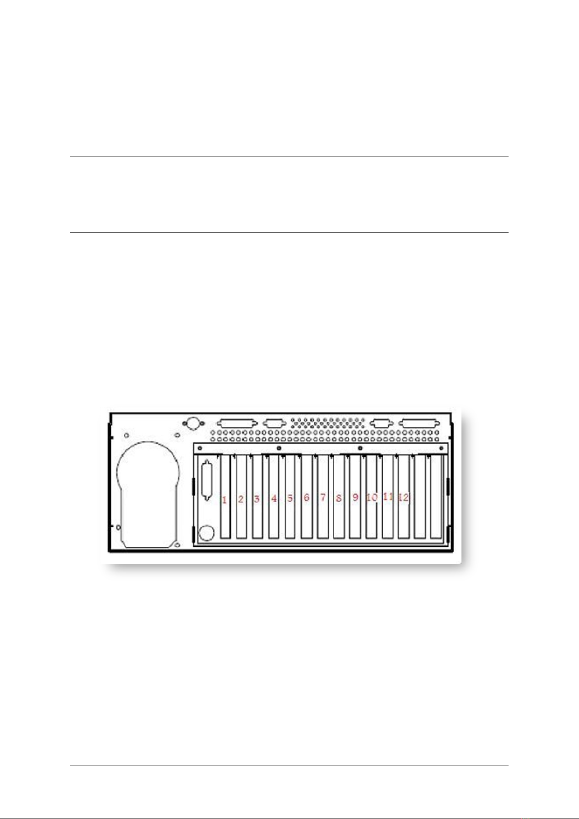
4.1 Numbering of the input sources
The input devices will be numbered from 1 to 12, please observe input card numbering on the
rear of the gateway.
4.2 Satellite connection
Each DVB-S and DVB-S2 input has a standard F connector. Each input can be configured
individually with regard to selecting band/polarity and up to four different satellite positions
using DiSEqC multiswitches.
11

System Installation Guide, Release 1.0
4.3 Terrestrial connection
Each DVB-T input has a standard IEC 169 connector (also called Belling-Lee or TV Aerial
Plug).
4.4 CA modules
Some DVB inputs, depending on configuration, have an associated CAM slot to descramble
pay TV channels. The CAM slot can be located on the same space as the input connector or
on a neighboring space, depending on configuration. Most EN 50 221 compatible CA modules
may be used, but ask your sales contact for verification whether a given module type works.
Insert your program card into the CAM and then insert the CAM into its slot before tuning and
configuring the channel. Note that it may take some time from the channel is first tuned until it
works as expected when the program card is new or have been unused for a while.
4.5 Analog sources
Each analog input slot has a number of different connectors, but only one video and one audio
can be used at once. The inputs normally available are stereo RCA audio connectors, S-video,
RCA composite video and RF-tuner inputs. The stereo audio connectors are to be used in
conjunction with both S-video and composite video input. When using the tuner both video
and audio will be received from the RF input. Sometimes two neighboring slots may share one
RF connector.
4.6 List inputs
12 Chapter 4. Manage inputs

System Installation Guide, Release 1.0
You are represented with a table of available inputs cards in the server that can be tuned up.
You can click on any input, the numbering of the inputs will align with the physical labeling on
the rear of your unit. See section Add channel from input for how to tune channels from input
card.
4.6. List inputs 13

System Installation Guide, Release 1.0
14 Chapter 4. Manage inputs

CHAPTER 5
Manage live signals
5.1 List and edit channels
TV and Radio channel can be found on seperate pages.
TV channels can be displayed by clicking in menu Manage Live signals →List TV channels.
Radio channels can be displayed by clicking in menu Manage Live signals →List Radio
channels.
5.1.1 Edit channel
In menu click Manage Live signals →List TV channels (List Radio channels). Press Edit
for the channel you want to edit.
15
This manual suits for next models
7
Table of contents
Other SnapTV Server manuals


