SND FB-14 Mk2 User manual

FB-14 Mk2
Discrete Inductive Fixed Filter Bank
SND
User manual
www.s-n-d.com

Note: The circuit and thus the sound of the machine is an accurate re lica of the first roduction
run from 20 years ago. The Mk2 refers to only minute changes in the outer design
Introduction
O eration of the FB-14 is sim le and straightforward. None the less we recommend even to
ex erienced users to quickly browse through these notes, in order to achieve o timum results.
When choosing a lace for the FB-14, two as ects should be taken into consideration. First -
although it may seem obvious - we strongly recommend a lace at which the machine can be
o erated without leaving the referred listening osition (i.e. not in a rack just above the floor) in
order to be able to objectively judge all the sonic nuances. Also one should avoid to mount the
FB-14 in a rack immediately above or below gear with strong ower su lies (and thus strong
electromagnetic fields). Because of the coils used in the FB-14's filters this could cause audible
hum.
The external ower su ly is a s ecial AC ty e. Connecting other standard DC ower su lies
should not damage the FB-14, but it also won't work.
Audio connections
Fig. 1 shows the sim lest and most common way to connect the FB-14. When connecting it using
a mixers insert oint (Fig. 2), the signal can am lified before getting to the filter. When using a
mixer with switchable subgrou s a convenient method of sending different signals through the
FB-14 without re- atching, is to connect the filter to an unused subgrou s insert oint and route
the desired in ut to that subgrou (and turn off the in uts master routing).
Fig. 3 is normally used only with reverb or echo devices, but they also make sense with filters.
Mixing the dry and the filtered signal not only allows crossfades. Using the various hase
shiftings roduced by the mixers internal eq's and the hase-reverse switch (found at least on
studio consoles) it is ossible to create all kinds of interesting cancellations.
Should groundloo s occur when mounting the FB-14 into a rack, it is ossible to se arate the
machine's audio ground from its chassis. Remove the 6 Phili s-head screws and the 2 audio jack
lastic nuts and take off the back cover. Viewed from the front, there is a jum er at the very left
end of the rinted circuit board (marked groundlift). Remove the jum er. In order to save it for
future uses, “store” it on one of its osts. Put the cover back on.
Fig. 4-6 show some unusual interfacing with studio effects devices. Ex eriment !

S ecial interfacing with studio effects:
By ass
Without ower a lied the FB-14 automatically feeds the in ut signal to the out ut com letely
unaltered (hard wire bypass). After a lying ower the device is activated (LED hell). By
ressing the Bypass-Button the device is com letely removed from the signal ass (LED
dimmied). Note: due to its circuitry the re onse will not be erfectly flat even with all filter
controls set to 0.
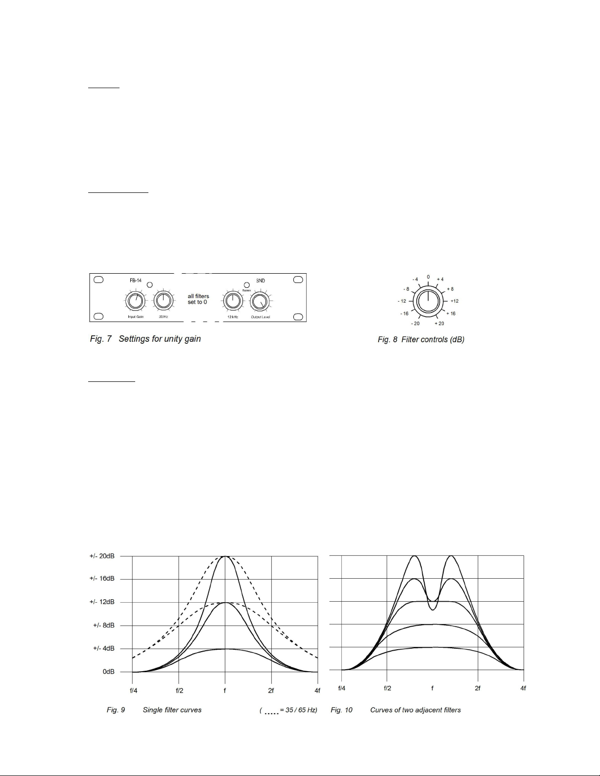
Level settings
The Input Gain-Control at the very left allows the in ut gain to be set between-18dB to +18dB.
The Output Level-Control at the very right controls the out ut signal from -∞ to 0db. Fig.5
shows the setting for 0dB overall gain (unity gain). Fig.6 shows the am lification/attenuation for
settings of individual filters.
The Filters
Between -12 and +12dB the filters act fairly broadband and without audible coloring, while they
become more and more narrow at more extreme settings. This resonance is most ronounced in
the middle bands, while the highest two and the lowest three bands remain broader. This has
roven to be the best combination in multi le listening tests. (Fig. 7).
When multi le adjacent bands are cranked u towards maximum, cross-cou ling between them
will cause di s of 2 - 8dBs. (Fig. 8). Since this design will overdrive the individual filters, the
sonic character of this overdrive can be influenced over a wide range. De ending on the in ut
signal and the gain setting it can range from soft tube-like sounds all the way to broken s eakers.
To use the full +20-dB range of each filter, it may be necessary to reduce the in ut signal or the
in ut gain.

Why:
Why rotary pots and no faders ?
Although faders may have their s ecial advantages (simultaneous o eration of multi le bands,
visibility) a im ortant argument against using them in the FB-14 is the non-linear curve of the
circuit used (meaning all audible changes ha en only near either end of the faders travel). Since
this circuit is an im ortant art the FB-14s s ecial sound, we had to find another solution, which
is to get ots with a s ecial curve (custom made by re uted manufacturer Al s). These are not
available as faders. Also, faders would have increased the overall size of the case by at least
factor 3.
Why no overload LED ?
Due to the wide control range of the individual filters measuring the level at all relevant oints
would have been rather involved. Since overdriving the unit creates some of the most interesting
sounds the FB-14 can roduce, we didn’t bother.
Why the choice of these frequencies ?
14 filters seemed like a good com romise between size and com onent count, as well as under
musical considerations. By lacing the bands about one fifth a art, a false tonality (an unwanted
em hasis of the same musical note in different octaves) is avoided. Widening the bands towards
the outer limits of the audible s ectrum was determined to be useful in many listing tests.
Why an e ternal power supply ?
Even though we normally dislike “wall warts” just like everybody else, there are several reasons
why we decided to use on. Firstly the use of coils in the FB-14s circuitry would have forced us to
move any internal ower transformer far away from them to avoid magnetic hum, and thus
increased the overall size significantly. Secondly, external ower su lies allow sim le
ada tation to the various mains voltage used worldwide.
Technical Data:
In ut Im edance 47 kOhm
Out ut Im edance 150 Ohm
Recommended Load > 10 kOhm
Max. In ut-Level 22 V (+26 dBv)
In ut Gain +/-18 dB
Max. Out ut Level
all filters set to 0 3.5 V (+10 dBv)
all filters set to max. 7.5 V (+17 dBv)
Control Range er Filter +/-20 dB
Frequency Range
All Filters set to 0 +/-1.5 dB @ 20-50000 Hz
Dynamics > 90 dB
Power su ly 12-15 Vac @ 100 mA
www.s-n-d.com
Table of contents
Other SND Recording Equipment manuals


