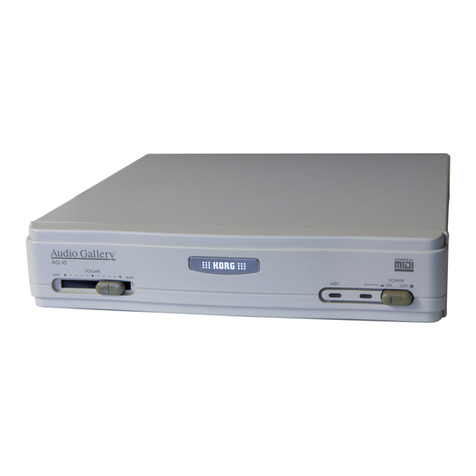
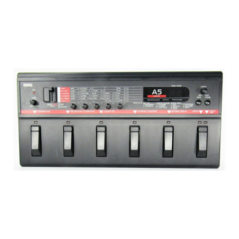
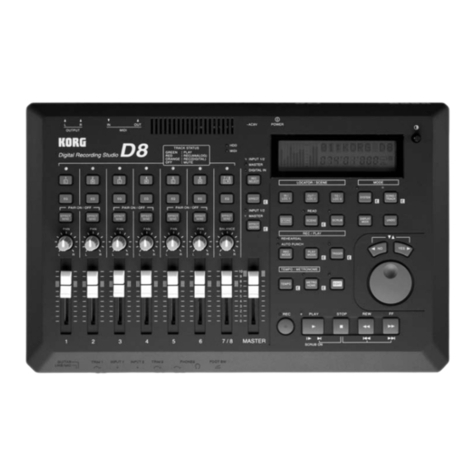
Korg A1 User manual

CONTENTS
OWNER'S MANUAL
Identification of Controls and Terminals... 4
Basic Operation .............................................................. 6
1. Preparation and Basic Connections......................6
2. Play Mode .............................................................8
3. Program Editing................................................... 12
The Four Modes and Their Functions............. 15
Play Mode ............................................................. 16
1. Program Selection ...............................................16
2. Turning Effects ON and OFF ................................. 9
3. Performance Edit ................................................ 20
4. Setting the Master Out Volume. Noise
Reduction Threshold Level and Bypass
Switching in the Play Mode ................................... 21
Edit Mode....................................................... 22
1. Chain Edit ...........................................................23
2. Effect Edit ...........................................................30
3. Program Utility ....................................................36
Write Mode ............................................................40
1. Write Operation ..................................................40
Global Utility Mode ...............................................44
1. Setting MIDI Functions......................................... 45
2. Loading Programs From and Saving
to Memory Cards .................................................48
3. Setting Internal Memory Protect Functions ..........50
4. Mapping Programs .............................................. 51
5. Setting Foot Switch Functions ............................. 52
6. Setting the Digital I/O Functions..........................53
Connecting the Optional RE1
Remote Editor........................................................ 54
Connecting the Optional
FC6 Foot Controller ................................................. 55
1. Manual 1 (Program Change Mode)....................... 56
2. Manual 2 (Effect ON/OFF Mode) ......................... 57
3. Connecting Foot Switch 1 and 2 to the SW1
and SW2 Jackson the FCS Rear Pane! .............57
A1 Connection Examples .................................58
1.Guitar Setup .........................................................58
2.Mixers and Multi-track Recorder Setup................. 59
3.Using the Digital I/O.............................................. 59
Troubleshooting..................................................... 60
List of Messages ..................................................... 61
Rack Mount Installation...........................................62
Specifications and Options ......……………………..63

Table of Contents
Identification of Controls and Terminals...... 4
Basic Operation................................................ 6
1. Preparation and Basic Connections................6
2. Play Mode .................................................. 8
1/ Selecting Programs.................................... 8
2/ Useful Functions .......................................10
Structure of Effect Programs ......................11
3. Program Editing............................................12
1/ Editing individual effect parameters ..........12
2/ Replacing an Effect ...................................14
3/ dealing a New Program..........................14
The Four Modes and Their
Functions ................................................... 15
Play Mode .............................................................16
1. Program Selection ........................................16
1/ Basic Play Mode........................................16
2/ Rearranging the Program Order- Map
Play .............................................................17
2. Turning Effects ON and OFF.......................19
3. Performance Edit ......................................... 20
4. Setting the Master Out Volume, Noise
Reduction Threshold Level and Bypass
Switching in the Play Mode ...........................21
Edit Mode......................................................... 22
1. Chain Edit......................................................23
Chains .......................................................... 23
Types of Chains ........................................... 23
Symbols Used to Show Effect Connection in
a Chain ..........................................................25
1/ Replacing effects in a Chain with
other effects...................................................26
2/ Selecting and editing a new Chain .............. 28
Chain Edit Using the RE-1........................... 29
2. Effect Edit..................................................... 30
Turning Effects ON and OFF ........................31
Compare Kay ................................................31
Using the Dynamic Modulation Function ......32
Setting the Dynamic Amount........................ 33
Copying Effects .............................................34
3. Program Utility ..............................................36
1/ Setting Levels ...........................................36
2/ Volume Pedal Placement..........................37
3/ Setting the External Control Functions .....38
Write Mode .................................................... 40
1. Write Operation....................................... 40
Global Utility Mode .................................... 44
1. Salting MIDI Functions .......................... 45
Receiving a System Exclusive Dump
from an External Device............................47
2.Loading Programs from and Saving
to Memory Cards..................................... 48
Using the ROM Card Included with
Your A1 ................................................. 50
3. Setting Internal Memory Protect
Functions ................................................ 50
4. Mapping Programs...................................51
Map Initialization.......................................51
5. Setting Foot Switch Functions ................ 52
6. Setting the Digital I/O Functions............. 53
Connecting the Optional RE1 Remote
Editor...........................................................54
Connecting the Optional FC6 Foot
Controller................................................... 55
1. Manual 1 (Program Change Mode] ........ 56
2. Manual 2 (Effect ON/OFF Mode)............ 57
3.Connecting Foot Switch 1 and 2 to the
SW1 and SW2 Jacks on the FC6 Rear
Panel ........................................................ 57
A1 Connection Examples............................55
1. Guitar Setup............................................ 58
2. Mixers and Mufti-track Recorder
Setup...................................................... 59
3. Using the Digital I/O................................ 59
Troubleshooting ....................................... 60
List of Messages .......................................... 61
1. Error Messages ........................................61
2. Messages.................................................61
Rack Mount installation............................. 62
Specifications and Options ...................... 63
MIDI Implementation Chart ........................ 64

WARNING
THE FCC REGULATION WARNING
This equipment generates and uses radio frequency energy and if not installed and used properly, that is,
in strict accordance with the manufacturer's instructions, may cause interference to radio and television
reception. It has been type tasted and found to comply with, the limits for a class B computing device in
accordance with the specifications in Subpart J of Part 15 of FCC Rules, which are designed to provide
reasonable protection against such interference in a residential installation. However, there is no
guarantee that interference will not occur in a particular installation. If this equipment does cause
interference to radio or television reception, which can be determined by turning the equipment off and
on. the user is encouraged to try to correct the interference by one or more of the following measure?:
• Reorient the receiving antenna.
• Relocate the equipment with respect to the receiver.
• Move the equipment away from the receiver.
• Plug the equipment into a different outlet so that equipment and receiver are on different branch
circuits.
If necessary, the user should consult the dealer or an experienced radio/television technician for additional
suggestions. The user may find the following booklet prepared by the Federal Communications
Commission helpful: "How to identify and Resolve Radio - TV Interference Problems", This booklet is
available from the US Government Printing Office, Washington DC 20402, stock No.004000-0003454-4.
CANADA
THIS DIGITAL APPARATUS DOES NOT EXCEED THE "CLASS B" LIMITS FOR RADIO NOISE
EMISSIONS FROM DIGITAL APPARATUS SET OUT IN THE RADIO INTERFERENCE REGULATION
OF THE CANADIAN DEPARTMENT OF COMMUN I CATIONS.
LE PRESENT APPREIL NUMERIQUE NENT PAS DE BRUITS RADDELECTRIQUES DEPASSANT
LES LIMITES APPLICASLES AUX APPAREILS NUMERIQUES DE LA "CLASSE B" PHESCR1TES
DANS LE REGLEMENT SUR LE BROUILLAGE RADIOELECTRIQUE EDICTE PAR LE MINISTERE
DES COMMUNICATIONS DU CANADA.

Identification of Control and Terminals
FRONT PANEL
1. DIGITAL IN Indicator
Lights up to indicate input of a digital signal.
2. L and R. RETURN (Input level} Indicators and
digital CLIP LEDs.
Indicates the level of the input signal. The CLIP Indicator
lights up when the input level becomes too hot. (The CLIP
indicator does not light up when effect processing levels
become excessive.)
3. INT (Internal) Indicator
Lights up during the operation at an internal program of
the Al.
4. CARD Indicator
Lights up during the operation of a program provided on
a memory card.
5. MAP Indicator
Lights up during the activation of Map Play Mode.
6. Program Number Display
Displays the current program number.
7. PAGE +, - (Page Up/Down] Keys
For selecting additional display pages when parameters
exceed one page.
8. LCD Screen
Indicates the current chain, parameters, etc.
9. Headphones Jack and PHONES Volume Control
For connecting headphones and adjusting the volume.
10. IN (Input) Volume Control and Input Jacks
(L/MDND,
R)
• L/MONO and R input jacks for connection of mono.
dual mono or stereo sources.
• Use the IN volume controls to adjust the level of the
L/MONO and R inputs.
• The front panel inputs have priority over the rear panel
inputs.
11. MASTER OUT Volume Control
For adjusting the output level. The volume level, set by
the MASTER OUT volume control, can be written to
each program independently.
12. THRESHOLD Level Control
For adjusting the noise reduction threshold level. The
threshold level can be written to each program
independently.
13. INT (Internal) and CARD Keys
Use the INT key for selecting programs stored within the
A1 and the CARD key to select programs stored on ROM
or RAM cards
14. MAP Key
Press to select Map Play Mode. Press again to cancel the
Map Play Mode.
15. Up/Down Keys
For selecting programs and adjusting parameters in Edit
Mode.
16. COMPARE Key
Press during editing to compare edited data with the
original data. Press again to restore the original data.
17. Mode Keys and Indicators
Press the mode keys to select the desired modes. LEDs
indicate the currently selected modes.
• PLAY: Play Mode for program playing and simple effect
parameter editing.
• EDIT: Edit Mode for modifying the contents of
programs.
• UTILITY; Global Utility Mode for setting MIDI and other
functions; press again to cancel.
• WRITE: Write Mode for saving programs to the A1
memory or memory card.
18. BYPASS Key
Press to bypass the effects and output only direct sound.
19. Double Function Edit Controls and Indicators (A-H)
Press the double function edit controls in Play Mode to
turn the corresponding effect ON or OFF. Press the
double function edit controls to turn effects on and off and
turn to adjust parameters in the EDIT MODE.
20 CARD Slot
For inserting optional ROM or RAM (MCR-03) cards.
21. POWER switch
For turning the power ON and OFF.

REAR PANEL
1. BALANCED OUTPUT Jacks
For connection to mixers and other equipment
having balanced inputs.
2. OUTPUT LEVEL Switch
Set to match the input level of the connected
equipment.
3. OUTPUT Jacks (R, L/MONO}
For connection to mixers and other equipment
having unbalanced inputs.
4. SEND, RETURN Jacks and LEVEL Switches
For inserting an external signal processor, guitar
preamp, etc. into the A1 elect signal path. The
SEND (output) and RETURN (input) are only
operational when the A1 program is using a
SEND/RETURN CHAIN. Set the level switches to
match the input/output level of the connected
equipment.
5. DIRECT OUT (STEREO) Jack
For direct left- and right-channel stereo sound
output.
6. INPUT Jacks {R, L/MONO) and LEVEL Switch
For connection to mixers, instruments, etc. Set the
LEVEL switch to match the output of the connected
equipment.
•USE the L/MONO input with a mono signal.
•With a mono input signal, set the R IN volume
control to match the L/MONO IN volume setting
•The inputs on the rear panel are stereo 1/4"
balanced
(tip/ring/sleeve) jacks. When a mono unbalanced
jack
is connected, the input level Is cut by approximately
half. Use the INPUT volume controls to
compensate
for the difference.
•The tip of the stereo phone jack is hot, the ring cold
and the sleeve ground.
7. MIDI Jacks (IN. OUT and THRU)
For connecting MIDI equipment.
8. REMOTE Jack
For connecting the optional RE I Remote Editor or the
FC6 Foot Contralto r.
9. DIGITAL AUDIO INPUT/OUTPUT Jacks
For connecting equipment with a sampling Frequency
of 44 kHz, such as DATs, digital amplifiers, and other
A1s.
10. EXT CTRL OUT (external control output) Jack
Conned to latching type footswitch inputs of external
signal processors or guitar preamps, etc. A1 program
changes can control bypass function or channel
switching or external devices.
11. BYPASS SWITCH Input Jack
For bypassing the processed sound and outputting
only the direct signal using a PS-1 momentary
footswitch.
12. FOOT SWITCH Input Jacks (1,2)
For connecting a PS-2 footswitch to control functions
such as Program UP/DOWN, etc. Connection setup
is performed in Global Utility Mode.
13. PARAM.(parameter)PEDAL Input Jack
Connect the output of aKVP-001 volume pedal to
this jack to control effect parameters, selected in the
Dynamic Modulation function, in real lime.
14. VOL.(volume)FEDAL Input Jack
Connect the output of a KVP-001 volume pedal to
this jack to control volume. Effect Chain placement of
the volume pedal is selected in the PROGRAM
UTILITY MODE.

Basic Operation
1 Preparation and Basic Connections
Before making connections, make sure that The POWER switch is OFF.
When connecting a guitar or keyboards:
1. Connect the guitar, etc. to the IN (Input) Jacks on the front panel.
• Connect a monaural sound sources such as a guitar to the L/MONO jack.
• Connect stereo sound sources such as a keyboard to the L/MONO and R jack.
2. Connect the mixer or guitar amplifier to the output terminal on the A1’s rear panel.
• Conned monaural sound sources such as a guitar amplifier to the L/MONO OUTPUT
jack.
• Connect to the L/MONO and R/OUTPUT jacks when playing back in stereo,
3. Set the OUTPUT LEVEL and INPUT LEVEL switches on the rear panel to -20
(dBm).

When connecting the A1 to the affect loop of a mixing console:
1. Connect the effect sand output of the mixer to the A1's rear panel Input.
• The inputs on the rear panel are stereo 1/4" balanced (tip/ring/sleeve) jacks. When a mono
unbalanced jack is connected, the input level Is cut by approximately hall. Use the INPUT volume
controls to compensate for the difference.
• The tip of the stereo phone jack is hot, the ring cold and the sleeve ground.
2. Connect the balanced or unbalanced outputs, on the A1'» rear panel, to the effect return
input of the mixer.
3. Adjust the OUTPUT LEVEL and INPUT LEVEL, on the A 1 ’ s rear panel, to +4 or -20 to match
the level of the mixing console.

2 Play Mode
1/Selecting Programs
The A1 has 100 factory preloaded programs
1. Connect a musical Instrument or Mixer to the A1 following
the steps on pages 6 and 7.
2. Set the Input volume 0.
3. Turn ON the POWER switch.
4. Set the Input volume level so that the Input Indicator lights
briefly at +6 dB during Input signal peaks.
5. Select the program number by pressing the UP/DOWN keys.
The A1's 100 preset programs are numbered I 00 to I 99. Program
199 ("A1 Example) is selected here as an example.

Playing with Program I 99
Turning On/Off the individual
Effects
Program I 99 is made up of four effects; Stereo Limiter (SLM1),
Stereo Exciter (SXIT), Stereo Delay (SDLY). and Plate
Reverb(PLI). You can play with four effects in program number
I99.
Each) program can combine up to 7 effects at the same time Any
effect can be set to OFF if undesired.
6. Press the "C" double function edit control.
The indicator under the "C" double function edit control turns
off. and the effect name ("SXIT") in the display changes to
lowercase letters ("SXIT") to indicate that the effect is OFF.
Listen to the difference in the processed signal when the Stereo
Exciter effect is OFF. Other effects can be toggled ON and OFF in
the same manner by pressing the corresponding A- H double
function edit controls.
7. You can turn the effect back on by pressing the "C" double
function edit control again, lighting up It's indicator.
Effects can be individually turned on and off in this manner far all
programs while in the PLAY mode.

2/Useful Functions
►Master Volume
►Noise Reduction Threshold Level
The MASTER OUT volume control adjusts the overall volume
level of the currently selected program. The level is indicated as a
value between 000 and 100 al the OUT indication in the top-right
portion of the display. The volume control Is active in all the
modes.
The THRESHOLD control can be used to adjust the noise
reduction threshold level of the selected program. The value is
shown at THR on the display. When the noise level is high, adjust
the control to a high value. The control is operative in all modes.
IMPORTANT: In Play Mode, the master volume output
and noise reduction threshold levels are set to the values
stored in memory every time a program is selected.
►BYPASS Switch
Pressing the BYPASS switch allows you to toggle between
activation and deactivation at effects during sound output.

Structure of Effect Programs
The A1 is an all-in-one multi-effect processor, capable of
simultaneously combining up to 7 effects in what is called a
Chain. The Chain data, along with user-selectable effects
and their parameter settings, are stored to programs.
Program Samples: A1 Example
Program
Chain
Effects
Variations
Parameters
Variables Common In All Effect
Programs
A program in the A1 is essentially an effect chain with effects, their
parameter and other settings in memory including a master output level
and noise reduction level and other settings.
An A1 program is an assembly of up to seven effects, which may be
simply considered as seven different effect devices linked together. The
pattern in which effects are linked is called a Chain. A Chain is the
connection pattern in which boxes (effect boxes) are lined up.
The A1 contains 59 families of effects, all of which can be allocated to
effect boxes to create different programs.
Different parameter patterns of an effect produce what are called
Variations of the effect. For example, reverb comes in a Variation of
Hall, Room, and Plate.
Elements called parameters determine the characteristics of an effect,
and can be assigned numerical values by the user.
• Threshold level - threshold level of the built-in noise reduction system
• Master volume - overall volume of the program
• Volume pedal placement
•External control position setting

3 Program Editing
The A1 allows you to edit its preset programs to create your own custom programs.
1/Editing Individual Effect Parameters
Editing program I99
1. Press the Play Mode key.
2. Select the program to be edited using the UP/DOWN keys.
3. Press the EDIT key.
'EDIT SELECT" is shown on the display.
Press the "C" double function
edit control to Change the level
of the Stereo Exciter effect

Press the "E" double function edit
control to show "Right Blend" on
the display
5. Press the double function key below the parameter you wish to change.
The parameter name is displayed in the top right portion of the screen.
Rotate the "E" double function
edit control to change the
strength of the right-channel exciter.
6. While monitoring the sound, set the desired value for each parameter by
rotating the double function edit control under the respective parameter,
Since the LINK parameter of Stereo Exciter is on in this program, the value of Left Blend
is changed at the same (urns as Right Blend.
7. Edit the parameters by rotating the double function edit control under the
other parameters.
8. Change the contents of other effects by repeating steps 3 to 7 above.
Refer to "EFFECTS AND PARAMETERS" for details on the operation of each effect
parameter.

2/ Replacing an Effect
Replacing PL1 In program I 99
The A1 allows you to freely substitute effects in programs with others, as long as the
other effects can fit into the respective effect box.
1. Display EDIT SELECT by following steps 1 to 3 on page 12.
2. Press the PAGE + key,
"CHAIN EDIT" is shown on the display. Now you can replace an effect with
another.
Replacing "PL1" Plate Reverb
with "CHO11 Chorus
3. Select a new affect by turning the double edit control under the desired affect.
For example, replace "No.1 PL1 Plata Reverb" with "No.22 CHO Chorus" by
turning the "E" double function edit control.
After turning the "E" double function edit control, you may also find the desired effect by
scanning them one at a time with the UP/DOWN keys.
Refer lo "EFFECTS AND PARAMETERS" In find the effect order and number.
4. Similarly, replace one effect with another by turning the other double
function edit controls.
To save the edited program:
In the Write Mode, store the edited program in memory (see page 40). A program that
has just been edited will return unaltered lo its original form if you select another
program without executing the write operation.
3/ Creating a New Program
The procedure far creating a new program is outlined below. For the details, refer to
"The Edit Mode" on page 22.
1. Selecting 3 Chain
Select one type of chain, (ram the five types (Serial. Parallel, etc).
For the chain selection procedure, and the types of chains, refer to "Chain Edit" on
page 23.
2. Selecting an Effect
Place the effects to be used in the boxes of the selected chain. Refer to "Replacing
Effects" on page 26.
3. Setting effect parameters
Set a series of parameters that create the effect sound you want to have. Refer to
"Effect Edit" on page 30.

The Four Modes and Their Functions
In addition to Play Mode and Edit Mode, the A1 has two additional modes for a total of A:
Write Mode for storing programs in memory and Global Utility Mode which provides
supplementary functions.
The relationship between the lour modes is illustrated by the chart below.

Play Mode
The Play Mode indicator lights up when the At is in Play Mode, at which time you can freely select
and play any of 100 preset effect programs or programs provided on A1- compatible memory
cards. The Play Mode also contains a Performance Edit Mode that allows real lima editing of
selected effect parameters.
1 Program Selection
Using the UP/DOWN keys, you can select programs that have been factory set within
the A1 itself or stored on memory cards.
1/ Basic Play Mode
1. Press the Play Mode key to select Play Mode.
The Play Mode is automatically^ selected when the POWER switch is turned on.
2. • To select a program preset In A1:
Select a program number using the UP/DOWN keys.
• To select a program from a memory card:
1. Press the INT/CARD key. The CARD indicator lights up.
2. Select a program number using the UP/DOWN keys.
Press the INT/CARD key again turns on the INT and returns to the preset program
selection mode.
Holding down the UP or DOWN key enables continuous scrolling through the program
numbers.

2/ Rearranging the Program Order - Map Play
Map Play allows you. lo reorganize programs for performance or remap incoming MIDI
programs to A1 internal programs.
Map Edit
Preparation
The Map Edit mode area Is where edits to the Map Play program order is done.
1. Press the Utility Mode key to show the Global Utility Menu on the display.
2. Press the "E" double function edit control to select Map Edit Mode.
The display indicates that internal program 00 is assigned to map number 00.
First, set the desired program (ie., the program to be used first) to map number 00.
Storing program
numbers as map
numbers
3. Select INT or CARD by turning the "D" double function edit control.
Specify “INT” to select internal programs in the A1 or "CARD" to select programs from a
memory card.

4.Turn the "E" double function edit control to select the first program number
to be played.
As an example, specify 99.
Program number I 99 has been registered as map number 00.
5. Press the "A" double function edit control once to advance to 01.
As an example, set program I 98 to the next map number Map number 00 as shown in
the upper part of LCD end map number 01 in the lower part.
6. Repeat steps 3 to 5 to set other program numbers In the order to be played.
7. After setting all map numbers:
• Press the "H" double function edit control to return lo the Global Utility menu, or press
the PLAY key to return lo Play Mode.
To change a map number selling, turn the "C" double function edit control or press the
"A" and "B" double function edit controls to change the number one at a time to select
the new map number.
Checking program order
In Map Play
1.
Press the PLAY key to light up the Play Mode Indicator.
2. Press the MAP key to light up the Map Indicator.
• Map number "00* is shown in the red LED display.
• The previously assigned program number I 99 is shown in the LCD display.
•
To begin Map Play using the optional RE1: Press the "INF and "CARD" key at the same
time lo display the map number at the bottom-left portion of the REI's display.
3. Press the UP key to advance to the next map number.
Pressing it once advances to previously assigned program number I SS
Each press of the UP key advances the program number in the order they were stored
.
4. To EXIT the Map Mode, press the MAP key again.
The INT Indicator lights up and the A1 returns to the basic Play Mode.
However, if you EXIT the Map Mode while on a Map number assigned to a card-stored
program, the "CARD" indicator lights up and the A1 will be reading programs from an
inserted card in the basic Play Mode.
IMPORTANT:
Even after powering down, data created in Map Edit
Mode is saved in memory until next changed.

2 Turning Effects ON and OFF
In the Play Mode individual effects in a Chain can easily be turned on and off using the
double function edit controls. This function makes h very easy to modify an effects program
in real time during a live performance or studio session.
1. Press the PLAY key to select Play Mode.
The Play Mode indicator lights up.
2. Select a program.
3. Press the double function edit control Immediately below the displayed name of the
effect to be turned on or off.
An effect is on when the effect name is shown in capital letters and the indicator of the double
function edit control is turned on; an effect is off when the effect name is shown in lowercase
letters and the indicator of the double [unction edit control is not lit.
4. Press the double function edit control to turn the effect on again.
•
The display on the RE1 indicates that an effect is ON or OFF by showing its name in capital
or lowercase letters, respectively.
Effect ON/OFF settings can be saved in Write Mode.
IMPORTANT: Certain effects, such as MIXER and INPUT SWITCH, cannot be turned off by
pressing a double function edit control.

3 Performance Edit
The Performance Edit function of the Play Mode allows easy "real time* editing of
selected effect parameters. For a detailed list of the actual effect parameters available in
this mode, please refer to the "EFFECTS AND PARAMETERS".
1. Press the PLAY key to select Play Mode.
The Play Mode indicator lights up.
2. Select a program.
As an example, select 1 99, "A1 Example."
3. Press the PAGE key.
“PERFORMANCE EDIT" is displayed in the top-right of the display.
Changing the Stereo Exciter
(SXIT) BLEND level
4.
Turn the double function edit control of the effect to be changed.
The
effect name shown on the display is replaced by a numerical value. The
parameters of the effect that can be modified in Performance Edit mode are
shown.
The double function edit control is + 00 al center, and a maximum of ±50%
when turned. When set at ±00, The parameter setting is the same as the value
written to the program
To return to Play Mode
1
press the PAGE-key.
Changes made to parameters with the Performance Edit function can be saved to
memory by executing a writing operation in Write Mode.
Table of contents
Other Korg Recording Equipment manuals

Korg
Korg VIF3 User manual

Korg
Korg Sound on Sound User manual

Korg
Korg SE-300 User manual

Korg
Korg Pa50 User manual

Korg
Korg ToneWorks Pandora PX3B User manual

Korg
Korg Pandora PX5D User manual

Korg
Korg SQ-1 User manual

Korg
Korg nanoKONTROL Studio User manual

Korg
Korg KONTROL49 User manual

Korg
Korg D1200 mkII Product information sheet

Korg
Korg nanoKey User manual

Korg
Korg SQ-64 User manual
Korg
Korg Karma User manual

Korg
Korg MR-2000S User manual

Korg
Korg KAOSS PAD KP2 User manual

Korg
Korg Pearl e/MERG MDL1 User manual

Korg
Korg D3200 User manual

Korg
Korg EFGS 1 User manual

Korg
Korg D16XD Product information sheet

Korg
Korg Pandora PX1 User manual