SNDWAY SW-6510S User manual

ULTRASONIC THICKNESS GAUGE
SW-6510S
mm
4.27
Scan
Mat:
5920Steel
mmMax
mmMin
mmAvg
ULTRASONIC
THICKNESS GAUGE
User Instruction
Please read this instruction intently before your
first utilization.
1. The instrument is not allowed to disassemble or repair in any
ways.It is forbidden to do any illegal modification or perfor-
mance change for laser emitter. Please keep it out of reach of
children and avoid being used by any irrelevant personnel.
2. Due to electromagnetic radiation interference to other equip-
ment and devices, please don`t use the device in the plane or
around medical equipment and don`t use it in an inflammable,
explosive environment.
3. Discarded batteries or devices shall not be processed just like
household garbage, please handle them in line with related
laws and regulations.
4. If the company's products beyond the warranty period are
faulty, they can be handed over to the company to repair the
product, and the maintenance fee will be charged according
to the company's regulations.
5. The company cannot provide warranty for any damage to the
product caused by the user's own disassembly and assembly
of the company's products, improper transportation, storage,
or failure to operate according to the product manual, as well
as unauthorized alteration of the warranty card without proof
of purchase.
6. If there is any quality problem with the instrument, or if you
have any questions about the use of the instrument, please
contact the local distributor or manufacturer in time, and we
will solve it for you as soon as possible.

- 01 -
2 Overview
1 Packing List
This instrument is an intelligent ultrasonic thickness gauge. It
adopts the latest high-performance, low-power microprocessor
technology. Based on the principle of ultrasonic measurement,
it can measure the thickness of metals and other materials, and
can measure the sound speed of materials. It can monitor
various pipes and pressure vessels in production equipment,
monitor their thinning degree after being corroded during use,
and can also accurately measure various plates and various
processed parts. This instrument can be widely used in
petroleum, chemical industry, metallurgy, shipbuilding, aviation,
aerospace and other fields.
No. Names Quantity Remark
1 User Manual 1PC
1PC
1PC
1PC
1PC
1PC
2
3Standard Probe(5mhz Ф10)
4 Coupling Agent
5 Portable Package
6 USB Cable
The Meter
Standard Configuration
- 02 -
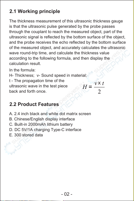
2.2 Product Features
A. 2.4 inch black and white dot matrix screen
B. Chinese/English display interface
C. Built-in 2000mAh lithium battery
D. DC 5V/1A charging Type-C interface
E. 300 stored data
2.1 Working principle
The thickness measurement of this ultrasonic thickness gauge
is that the ultrasonic pulse generated by the probe passes
through the couplant to reach the measured object, part of the
ultrasonic signal is reflected by the bottom surface of the object,
and the probe receives the echo reflected by the bottom surface
of the measured object, and accurately calculates the ultrasonic
wave round-trip time, and calculate the thickness value
according to the following formula, and then display the
calculation result.
In the formula:
H- Thickness; v- Sound speed in material;
t - The propagation time of the
ultrasonic wave in the test piece
back and forth once.

- 03 -
2.3 Technical Parameter
Note: 1) The standard probe of the instrument cannot use oily
couplant, otherwise the probe will be damaged! After using
the probe, wipe off any residual couplant on the probe to
prolong the life of the probe.
2) Please try to avoid using it in an oily environment. If it is
unavoidable, try to reduce the contact time with oily substances
as much as possible, and after use, dry the probe surface with
oil-absorbing paper.
300 sets, each set including current material,
Velocity of Sound, Unit, Measuring Value, the
MAX value, the MIN value and Average Value
Display 2.4 inch black and white dot matrix screen
Sound Velocity (1000~9999) m/s
Lower limit of pipe
measurement Ф20*3mm(steel)
Battery Built-in 3.7V 2000mAh Li-ion battery
Battery life
(fully charged) About 16 hours
Charging
specification DC5V 1A Type-C interface
Working Temperature
& Humidity 0°C~40°C, 10%RH~80%RH
Storage Temperature
& Humidity -10°C~+50°C, 10%RH~70%RH
Dimension 140x66x28.5mm
Unit 0.1mm / 0.01mm / 0.01in
Language Chinese / English
Measuring Range 1.00~300.00mm(the steel)
Main Functions
Single Measurement, Continuous
Measurement, Alarm Measurement,
Sound Velocity Measurement, Calibration
Accuracy H<10mm, ±0.1mm; H≥10mm, ±(1%H+0.1)mm
H is the thickness of the object
Storage capacity
ITEMS SW-6510S

- 04 -
3 Structure and appearance
1. Housing 2. Buttons 3. Display
4. Transmitter socket 5. Receiver socket
6. Thickness calibration block 7. Nameplate
8. Ultrasonic thickness probe (probe for short)
7
mm
20.00
Scan
Mat:
5920Steel
mmMax
mmMin
mmAvg
3
2
1
8
45
6

- 05 -
4 Charging and maintenance of lithium battery
3.1 Main Display Interface
After the instrument is turned on, it will automatically enter the
main display interface, as shown in the following figure:
1) Coupling state: the coupling state between the probe and
the workpiece to be measured
2) Measurement mode: display the current measurement mode
3) Unit system: mm (in metric system), or in (in imperial system)
4) Battery power: Display of remaining battery power
5) Sound indication: alarm sound switch display
6) Information display: display thickness measurement value,
measurement material, sound speed, maximum, minimum,
average;
The product is powered by a built-in 3.7V 2000mAh lithium
battery, which is not removable. When the product cannot be
turned on or the battery is empty after turning on, please
charge it in time. Please use a DC5V, more than 1A charging
adapter to charge the product, and the charging port is Type-C.
While charging, the battery symbol scrolls to display.
When fully charged, the battery symbol becomes full.
mm4.42
Scan
Mat:
5920Custom 1
4.50mmMax
4.42mmMin
4.43mmAvg
1
5
4
3
6
2

- 06 -
A. Prepare the tested workpiece, refer to "6.1 Surface
Treatment of Measured Workpiece".
B. Insert the probe into the instrument and turn it on.
C. Instrument calibration. Refer to "7.5 Instrument Calibration".
D. Inversely measure the speed of sound. The sound speed of
the workpiece is uncertain, and the sound speed must be
measured back to obtain the correct sound speed of the
workpiece. Refer to "7.6 Reverse Measurement of Sound
Velocity".
E. Measure the thickness. Use the inversely measured sound
velocity value to measure the thickness of the workpiece of
the same material.
Note: When not in use for a long time, fully charge the product
first, and recharge it every six months to avoid battery damage.
6 Preparation before measurement
5 The general measurement process of the
instrument
6.1 Surface treatment of the workpiece to
be tested
If the surface of the object to be measured is rough or severely
corroded, please use the following methods:
● Use couplant on the surface of the measured object;
● Use rust remover, wire brush or sandpaper to treat the
surface of the measured object
● Multiple measurements around the same point

- 07 -
7 Instrument use
7.1 Turning the instrument on and off
Power on: Insert the probe into the instrument, short press the
key to power on.
Power off: long press the key to power off.
Automatic shutdown: the instrument will automatically shut
down if there is no operation, and the default time is 5 minutes.
Users can change the automatic shutdown time, refer to
"7.18 Shutdown Settings".
Forced shutdown: long press the power button for more than
10 seconds to force shutdown.
Apply the couplant evenly to the tested area, tightly couple the
probe to the surface of the tested material, and the screen will
display the thickness of the tested area. When the probe and
the material to be tested are well coupled, the screen will display
the coupling mark . If the coupling mark flashes or there is no
coupling mark, it means that the coupling is not good and needs
to be added with couplant. When the probe is removed, the
coupling symbol disappears and the thickness value remains.
7.2 single measurement
Figure 1. Add couplant.

- 08 -
Figure 2. Smear the couplant evenly, and tightly couple the
probe to the surface of the material to be tested.
Apply the couplant evenly to the measured area, then couple
the probe to the workpiece and move it along the surface of the
workpiece. The instrument will display the current value,
maximum value, minimum value and average value of the
measurement in real time.
7.3 Continuous measurement
7.4 Alarm measurement
The user can monitor the material with poor quality through the
alarm function. Press and hold to turn the alarm on or off.
The displayed on the screen means to open the alarm
measurement, and the displayed on the screen means to
close the alarm measurement.
For example:
Alarm setting: Standard value: 4.00mm
Tolerance limit: ±0.1mm (Refer to "7.19 Alarm Setting" for alarm
setting) When the measured thickness is less than 3.90mm or
greater than 4.10mm, the instrument will continuously issue a

- 09 -
7.5 Instrument calibration
Note: Probe calibration should be performed every time the
probe is replaced, the ambient temperature changes greatly, or
the measurement deviates.
When the instrument is used for the first time or has not been
used for a long time, please calibrate it first. Calibration must
use the calibration thickness block provided by the manufacturer.
After calibration, the material automatically becomes steel, and
the speed of sound becomes 5920m/s (0.233in/us).
"Beep beep beep" alarm sound, at this time, the thickness of
the object is detected to be unqualified. After the alarm, the user
can press any key to exit the alarm, or continue to measure.
1) Press and hold to enter the calibration mode, and the
screen displays "Please measure the calibration thickness
block" .
2) Referring to Figure 1 and Figure 2 in "7.2 Single
Measurement", apply the couplant evenly to the surface of
the standard thickness block on the case, and press the
probe on the couplant to make it in close and uniform contact
with the surface of the thickness block ; (Note: Do not apply
the couplant too thick, otherwise the instrument will record
the thickness of the couplant, resulting in a calibration error).
3) After the measured value is stable, press again to save
the calibration data. (Note: Before pressing , the displayed
value may not be 4mm. Please press again when the
value is stable. After calibration, the displayed value should
be within the range of 4±0.04mm, otherwise re-calibrate).
The calibration operation is as follows:
- 10 -
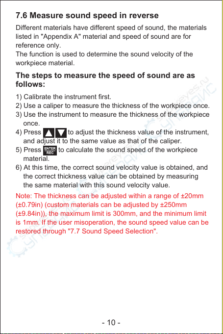
Different materials have different speed of sound, the materials
listed in "Appendix A" material and speed of sound are for
reference only.
The function is used to determine the sound velocity of the
workpiece material.
The steps to measure the speed of sound are as
follows:
1) Calibrate the instrument first.
2) Use a caliper to measure the thickness of the workpiece once.
3) Use the instrument to measure the thickness of the workpiece
once.
4) Press to adjust the thickness value of the instrument,
and adjust it to the same value as that of the caliper.
5) Press to calculate the sound speed of the workpiece
material.
6) At this time, the correct sound velocity value is obtained, and
the correct thickness value can be obtained by measuring
the same material with this sound velocity value.
Note: The thickness can be adjusted within a range of ±20mm
(±0.79in) (custom materials can be adjusted by ±250mm
(±9.84in)), the maximum limit is 300mm, and the minimum limit
is 1mm. If the user misoperation, the sound speed value can be
restored through "7.7 Sound Speed Selection".
7.6 Measure sound speed in reverse
- 11 -
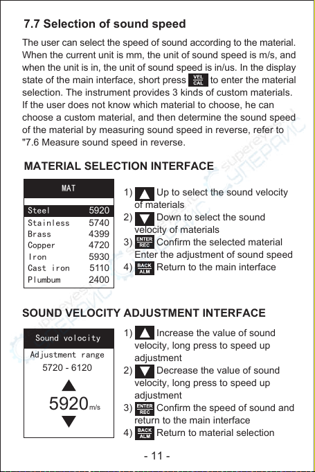
1) Up to select the sound velocity
of materials
2) Down to select the sound
velocity of materials
3) Confirm the selected material
Enter the adjustment of sound speed
4) Return to the main interface
Sound volocity
5920m/s
5720 - 6120
Adjustment range
1) Increase the value of sound
velocity, long press to speed up
adjustment
2) Decrease the value of sound
velocity, long press to speed up
adjustment
3) Confirm the speed of sound and
return to the main interface
4) Return to material selection
The user can select the speed of sound according to the material.
When the current unit is mm, the unit of sound speed is m/s, and
when the unit is in, the unit of sound speed is in/us. In the display
state of the main interface, short press to enter the material
selection. The instrument provides 3 kinds of custom materials.
If the user does not know which material to choose, he can
choose a custom material, and then determine the sound speed
of the material by measuring sound speed in reverse, refer to
"7.6 Measure sound speed in reverse.
7.7 Selection of sound speed
MATERIAL SELECTION INTERFACE
SOUND VELOCITY ADJUSTMENT INTERFACE
MAT
Stainless
Brass
Copper
Iron
Cast iron
Plumbum
5740
4399
4720
5930
5110
2400
Steel 5920
- 12 -
In single measurement and continuous measurement, long
press to save records, each record includes current
measurement value, maximum value, minimum value, average
value, and material sound velocity. The instrument can store up
to 300 sets of records. For viewing and deleting records, please
refer to "7.14 Recording Operation". Results of continuous
measurement cannot be saved until the probe is removed.
During measurement, measurement results cannot be saved to
prevent unstable data from being stored.
In single measurement and continuous measurement, short
press to clear the current measurement result (including
maximum value, minimum value and average value).
Continuous measurements do not clear the measurement until
the probe is removed.
7.8 CLEAR MEASUREMENT RESULT
7.9 Storage function

- 13 -
7.11 MATERIAL SELECTION
1) Select the previous option
2) Select the next option
3) Enter the selected option
4) Exit the menu and return to the
main interface
7.10 MENU
The menu includes: material selection, sound speed adjustment,
unit, recording operation, system setting, about, and factory
reset. Long press to enter the menu, the operation is as
follows:
Select from the menu.
1) Up to select material
2) Down to select material
3) Confirm the selected material
and return to the menu
4) Return to menu
Menu
Speed
Unit
Records
Setting
About
Reset
Material
Mat
Custom 1 5920
Custom 2
Custom 3
Aluminum
Steel
Stainless
Brass
5920
5900
6370
5920
5740
4399
Material

- 14-
Unit
0.1mm
0.01mm
0.01in
Select in the menu to adjust the range of sound speed
settings: The default value is ±200m/s (0.008in/us), and the
adjustable range of custom materials is: 1000m/s to 9999m/s
(0.039in/us to 0.394in/us).
1) Increase the value of sound
velocity, long press to speed up
adjustment
2) Decrease the value of sound
velocity,long press to speed up
adjustment
3) Save and return to menu
4) Return to menu
7.13 UNIT SETTINGS
7.12 THE ADJUSTMENT OF SOUND VELOCITY
Select in the menu.
Unit
1) Up to select units
2) Down to select units
3) Save and return to menu
4) Return to menu
Spd
5920m/s
Speed

- 15 -
DATA
002 4.44mm
003 4.42mm
001 4.50mm
Select the "Browse from the first page" function in the record
operation interface, the instrument will display the record list
from the first page of records, and display the record number
and current value of each record.
1) Page up
2) Page down
3) Enter the selected page
4) Return to the record interface
1) Up to choose functions
2) Down to choose functions
3) Enter the selected functions
4) Return to the menu
Select in the menu. When the instrument has no
record, it will prompt "no stored value" and cannot enter the
record operation.
7.14 RECORD
7.14.1 Browse from the first page
Records
first page
last page
selected item
Delete the item
Delete all
Records

- 16 -
In the record operation interface, select the "Browse from
selected group" function, the user selects the record to be
browsed, the instrument displays the record list from the page
where the record is located, and displays the record number
and current value of each record.
In the record list and record details functions, the user can long
press to delete the currently browsed record. Short press
to view the previous or next record details.
View record details: Enter the selected page, press
to select the record number, and press to view the details
(details include record number, current value, maximum value,
minimum value, and current value). After viewing details, short
press to return to the record list.
Select the "Browse from the last page" function in the record
operation interface, the instrument will display the record list
from the last page of records, and display the record number
and current value of each record. Please refer to 7.14.1. for
the operation.
7.14.2 Browse from the last page
7.14.3 Browse from selected groups
Data
001
4.50mm
Mat:
Custom 1 5920
Max: 4.50mm
Min: 4.50mm
Avg: 4.50mm

- 17 -
Select group
Select group
From 001 to 009
001
Del Group
group range
(001--009)
From to 001
001
1) Adjust the record number
2) Confirm the number of digits
currently modified (hundreds/tens/
units of record number), When the
units digit is confirmed, enter the
selected record number
3) Return to the record operation
interface
7.14.4 Deleted selected groups
In the record operation interface, select the "Delete Selected
Group" function, and the user can select the record to be deleted.
Deletion prompt: In this interface, the user can confirm whether
to delete. Use to select "Yes/No", select Yes, press
to delete; select No, press to return to the interface to
delete the selected group. Press to directly return to the
delete selected group interface.
It will take a while to delete the record,
and the instrument will prompt that it is
being deleted.
1) Adjust the record number
2) Confirm the number of digits
currently modified (Hundreds digit of
start record/end record/tens/units),
when the unit of the record is
terminated, enter the deletion prompt
3) Return to the record operation
interface
Deletion
Yes No
Delete
001-001

- 18-
Setting
Back light
Power off
Alarm
Language
Sound
Del
Do you confirm
to Delete all
saved data?
Yes No
7.15 system settings
Select in the menu.
Setting
1) Up to select functions
2) Down to select the function
3) Enter the selected function
4) Return to menu
Select the "Delete All" function in the record operation interface,
the user can choose to delete all records. Use to select
"Yes/No", select Yes, press to delete all records; select No,
press to return to the record operation interface. Press
to directly return to the record operation interface.
7.14.5 Delete all records
Table of contents


