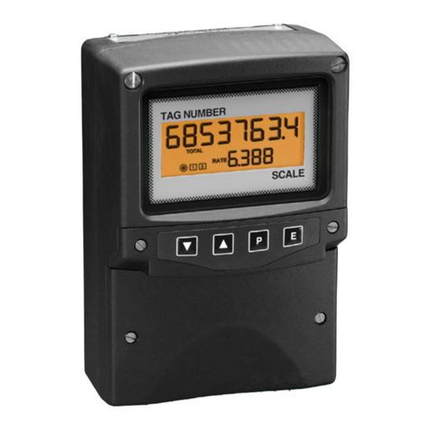
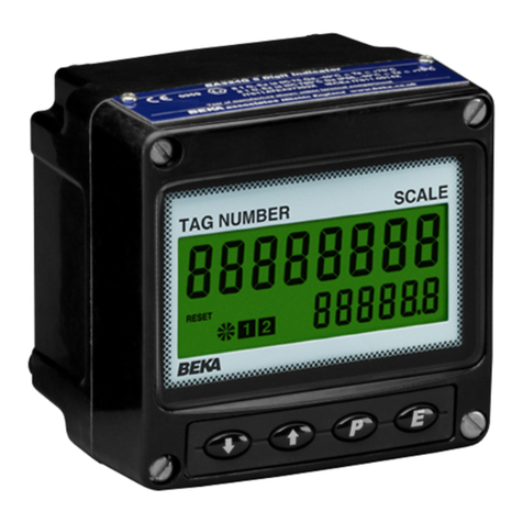
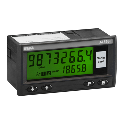
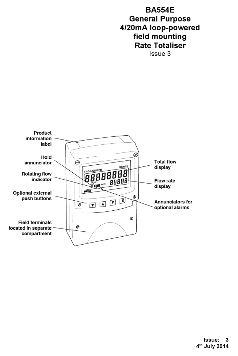
BEKA Advisor A90-SS User manual

Issue: 2
13th April 2017
Advisor A90-SS
Rugged universal process
panel meter with
multicolour display
Issue 2

1. Description
2. Operation
2.1 Controls
3. Applications
3.1 Power supply
3.1.1 Mains powered version
3.1.2 DC powered version
3.2 Signal inputs
3.2.1 Current input
3.2.2 Voltage input
3.2.3 Resistance thermometer input
4. Installation
4.1 Location
4.2 A90-SS earthing
4.3 EMC
4.4 Installation procedure
4.5 Scale card
5. Configuration and Calibration
5.1 Summary of configuration
functions.
5.2 Input type: input
5.3 Meter function: func
5.4 Units of temperature: deg
5.5 Display resolution: re5n
5.6 Decimal point: dp
5.7 Calibration of digital display using
external source: cal
5.8 Calibration of digital display using
internal reference: 5et
5.9 Trim temperature display: tri
5.10 Bargraph format and calibration: bar
5.11 Function of ( push button: u--p
5.12 Tare function: tare
5.13 Maximum andminimum hold
function: hold
5.14 Select meter display colour: color
5.15 Security code: code
5.16 Reset to factory defaults: r5et
5.17 Under and overrange
6. Maintenance
6.1 Fault finding during commissioning
6.2 Fault finding after commissioning
6.3 Servicing
6.4 Routine maintenance
6.5 Guarantee
6.6 Customer comments
7. Accessories
7.1 Scale card
7.2 Tag information
7.3 Alarms
7.3.1 Alarm relay contacts
7.3.2 Configuration and adjustment
7.3.3 Alarm enable: enbl
7.3.4 Setpoint adjustment: 5p1
7.3.5 Alarm function: hi.lo
7.3.6 Alarm relay energised or
de-energised in alarm
condition: nd.ne
7.3.7 Hysteresis: h5tr
7.3.8 Alarm delay: dela
7.3.9 Alarm silence time: 5il
7.3.10 Flash display when alarm
occurs: fla5h
7.3.11 Latch alarm output: latch
7.3.12 Display colour in alarm
condition: color
7.3.13 Access setpoint in display
mode: ac5p
7.3.14 Adjusting alarm setpoint from
the display mode
7.3.15 Display setpoints on the
bargraph.
7.4 4/20mA output and transmitter supply
7.4.1 4/20mA loop design
7.4.2 System design for powering a
transmitter.
7.4.3 Configuration and calibration
7.4.4 4/20mA enable: enbl
7.4.5 Display which corresponds to
4mA output: 4.000
7.4.6 Display which corresponds to
20mA output: 20.000
7.4.7 RTD fault detection: fault
22222222222
The A90-SS process panel meter is CE marked to show compliance with the European EMC
Directive 2014/30/EU and the Low Voltage Directive 2014/35/EU.
CONTENTS

1. DESCRIPTION
The Advisor A90-SS Rugged Universal Panel
Meter is a multicolour five digit instrument,
primarily intended for displaying a current, voltage
or resistance analogue process signal in
engineering units. The instrument can also display
temperature directly from a resistance
thermometer. The A90-SS is configurable on-site
using the four front panel push buttons and an
intuitive menu that can be protected by a security
code to prevent accidental adjustment.
Housed in a rugged stainless steel case with a
toughened glass window providing IP66 front of
panel ingress protection, the A90-SS is ideal for
installion in environments where it is liable to be
impacted.
The A90-SS Process Panel Meter employs a novel
technique that enables the display to be in any
colour on a black background, readable in all
conditions from total darkness to bright sunlight.
The display intensity is fully adjustable to match
other instruments and preserve operator's night
time vision.
When fitted with optional alarms the display colour
can be linked to the alarm status. For example, a
green display could indicate normal operation, the
display colour changing to red when a high alarm
occurs and to blue when a low alarm occurs.
The instrument input type and range are selectable
on-site and the meter display can be calibrated to
show the engineering variable represented by the
analogue input. The engineering units of
measurement such as kg, gallons/hour or ºC, can
be printed on the slide-in scalecard.
One of the following input ranges may be selected:
Voltage input
0 to 100mV
0 to 1V
0 to 10V
Current input
4 to 20mA
0 to 50mA
Resistance thermometer input
2 or 3 wire connected PT100 resistance
thermometer, or differential output from two
PT100 resistance thermometers.
-200 to 850ºC
There are two versions of the A90-SS Process
Panel Meter, one powered by a low voltage dc
supply and the other by a mains ac supply. The
instrument power supply type is shown on the label
adjacent to the power supply terminals 7 and 8.
dc powered model 10 to 36V
ac powered model 90 to 264V 47 - 63Hz
2. OPERATION
Fig 1 shows a simplified block diagram of the
A90-SS Process Panel Meter. Field wiring
terminals are the same for the low voltage dc
powered version and for the mains ac powered
version.
Terminals for the optional factory fitted alarms and
4/20mA output plus 24V transmitter supply are only
fitted when the option is included.
Each time power is applied to the meter
initialisation is performed during which all
segments of the display are activated, after a few
seconds the instrument enters the display mode
using the calibration information stored in the
instrument memory.
Fig 1 A90-SS panel meter block diagram
3

2.1 Controls
The Advisor A90-SS panel meter is controlled and
calibrated via the four front panel push buttons
located below the display. In the display mode i.e.
when the meter is displaying a process variable,
these push buttons have the following functions:
(While this button is pushed the meter
will display the input as a percentage of
the instrument span or, depending
upon configuration, the analogue input
in milliamps, volts or ohms.
When optional alarms are fitted and the
latch function latch is enabled,
pressing this button will de-latch the
alarm output.
When the alarm silence time 5il is set
to any value other than zero, operating
this button clears the alarm for the
configured silence time.
&While this button is pushed the meter
will display the numerical value and
analogue bargraph the meter has been
calibrated to display with a minimum
input I.e. 4mA or 0V. When released
the normal display in engineering units
will return.
If the hold function hold is enabled,
operating this button will cause the
meter to display the lowest value since
the hold function was last reset by
operating the &and * buttons
simultaneously.
*While this button is pushed the meter
will display the numerical value and
analogue bargraph the meter has been
calibrated to display with a maximum
input I.e. 20mA or 1V. When released
the normal display in engineering units
will return.
If the hold function hold is enabled,
operating this button will cause the
meter to display the highest value since
the hold function was last reset by
operating the &and * buttons
simultaneously.
)Unused unless tare function tare is
enabled. When tare function is
enabled operating this button for less
than 3 seconds toggles the meter
display between the gross and net
values. The ‘T’ annunciator is
activated when the net display is
shown. Operating the
)button for
more than 3 seconds tares the display
by setting it to zero.
) + &When both buttons are operated
simultaneously for more than 3
seconds slowly decreases display
brilliance.
) + *When both buttons are operated
simultaneously for more than 3
seconds slowly increases display
brilliance.
(+ &Shows firmware number followed by
version.
( + *Direct access to the alarm setpoints
when optional alarms are fitted to the
meter and the ac5p access setpoints
in display mode function has been
enabled.
& + *Resets the maximum and minimum
hold memories when the hold
function is enabled.
(+ )Access to configuration menu via
optional security code.
4

3. APPLICATIONS
3.1 Power supply
3.1.1 Mains powered version
The mains powered version of the A90-SS panel
mounting meter will operate from a wide range of
voltage and frequency ac supplies.
Voltage 90 to 264V rms ac
Frequency 47 to 63Hz
Power 2.5W
The supply should be well regulated and free from
transients.
3.1.2 DC powered version
The DC powered version of the A90-SS panel
mounting meter is designed to be operated from a
nominal 24V dc instrument power supply but, as
shown below, will function with a wide range
supply voltages.
Voltage 10 to 36V dc
Current 200mA at 10V
56mA at 36V
3.2 Signal inputs
The A90-SS panel meter can measure current and
voltage process signals and display them in
meaningful engineering units. The meter can also
display temperature in a variety of formats from a
Pt100 resistance thermometer primary element.
Selection of the input type is made within the
configuration menu which is described in section 5
of this manual. Input terminals also vary for
different inputs as shown in Fig 6.
3.2.1 Current input
The A90-SS panel meter can measure and display
in engineering units any process signal
represented by an analogue linear or square law
current such as a 4/20mA process signal. The
A90-SS has two current input ranges 4-20mA and
0-50mA dc.
The current input terminals 13 and 14 are
galvanically isolated from the A90-SS meter power
supply and all other outputs which allows the A90-
SS meter to measure the current in any process
loop without affecting the accuracy of the loop.
When connected in series with a current loop the
A90-SS panel meter introduces the following
voltage drops:
At 20mA 1.0V
At 50mA 1.5V
Fig 2 shows how the A90-SS panel meter should
be connected to measure a process current.
Fig 2 A90-SS Process panel meter measuring
current.
3.2.2 Voltage input
The A90-SS panel meter can measure and display
in engineering units any linear process signal
represented by an analogue voltage such as a 0 to
1V signal. The voltage input terminals 11, 12 and
13 are galvanically isolated from the A90-SS meter
power supply and all other outputs. There are
three dc voltage input ranges:
Input
Terminals resistance
0 to 0.1V 13 (0V) and 12 (+ve) 5MΩ
0 to 1.0V 13 (0V) and 12 (+ve) 5MΩ
0 to 10V 13 (0V) and 11 (+ve) 1MΩ
The input resistance of all the voltage inputs is high
allowing the A90-SS meter to measure any
process voltage signal without loading it and
changing the value. Fig 3 shows how the A90-SS
panel meter should be connected to measure a
process voltage.
Fig 3 A90-SS Process panel meter measuring
voltage.
3.2.3 Resistance thermometer input
The A90-SS panel meter can measure the
resistance of a single Pt100 BS EN 60751 platinum
resistance thermometer and display the
corresponding temperature in a variety of units
including ºC and ºF. The resistance thermometer
may be connected to the meter via two or three
wires. The differential output of two resistance
thermometers can also be measured and
displayed.
5

Fig 4 shows the connections for two and three wire
resistance thermometers and Fig 5 the
connections for differential measurements.
Fig 4 Connections for a 2 or 3 wire resistance
thermometer.
Fig 5 Connections for differential resistance
thermometer measurements.
6

4. INSTALLATION
4.1 Location
The A90-SS panel meter has a rugged stainless
steel case with a 10mm thick toughened glass
window. The case provides 7J and the window 4J
front of panel impact protection. The captive
silicone gasket, which seals the joint between the
instrument and the panel enclosure, ensures IP66
front of panel ingress protection. The instrument
has IP20 rear protection.
Although the front of the meter has IP66 protection,
it should be shielded from continuous direct
sunlight and severe weather conditions
The meter may be installed in any panel providing
that the operating temperature is between –40ºC
and +55ºC.
Fig 6 shows the overall dimensions of the
instrument together with the recommended panel
cut-out dimensions to achieve an IP66 seal
between the instrument enclosure and the
instrument panel.
4.2 A90-SS earthing
The A90-SS panel meter complies with the Low
Voltage Directive 2014/35/EU and has the
following isolation between circuits:
AC powered model supply input 3kV rms
DC powered model supply input 1.5kV
Alarm contacts 4kV rms
All other circuits 500V rms
The A90-SS stainless steel enclosure is totally
isolated from the meter circuits but for personnel
safety should be earthed. This can be achieved
via the earth terminal on the meter power supply
plug, or via the M4 earth stud on the rear panel of
the meter.
Fig 6 show the overall dimensions of the indicators
together with the recommended panel enclosure
cut-out dimensions.
Fig 6 A90-SS meter dimensions and terminals
Panel wiring should be supported to prevent
vibration causing damage to the wiring or
terminals.
4.3 EMC
The A90-SS panel meter complies with the
requirements of the European EMC Directive
2014/30/EU. For specified immunity all signal
wiring should be screened with the screens
earthed at one point. Voltage and current input
wiring should be in twisted pairs.
7

4.4 Installation Procedure
a. Cut the aperture specified in Fig 6 in the
panel enclosure. Ensure that the edges of
aperture are de-burred.
b. Inspect the meter's captive gasket and
ensure that it is not damaged before inserting
the meter into the panel enclosure aperture.
c. If the enclosure panel is less than 1.0mm
thick, or is non-metallic, an optional BEKA
stainless steel support plate should be slid
over the rear of the indicator before the panel
clamps are fitted to evenly distribute the
clamping force and prevent the enclosure
panel being distorted or creeping.
d. Slide a panel clamp into the two grooves at
each corner of the indicator housing with the
M3 stud protruding through the hole at the
rear of the clamp. Fit the stainless steel
spring washer over the stud and secure
with the stainless steel wing nut.
e. Evenly tighten the four clamps to secure the
instrument. The recommended minimum
tightening torque for each wing nut is 22cNm
(1.95 lbf in).
f. Connect the panel enclosure wiring to the
rear terminal blocks. The terminals may be
removed from the instrument by pulling.
Fig 7 Fitting panel mounting clamps
4.5 Scale card
The meter’s units of measurement may be shown
on a scale card visible through a window at the
right hand end of the display. The scale card is
mounted on a flexible strip that is inserted into a
slot at the rear of the instrument as shown in Fig 8.
Thus the scale card can easily be changed without
removing the meter from the panel or opening the
instrument enclosure.
New meters are supplied with a printed scale card
showing the requested units of measurement. If
this information is not supplied when the meter is
ordered a blank card will be fitted.
A pack of self-adhesive scale cards printed with
common units of measurement is available as an
accessory from BEKA associates. Custom printed
scale cards can also be supplied.
To change a scale card, unclip the protruding end
of the flexible strip by gently pushing it upwards
and pulling it out of the enclosure. Peel the
existing scale card from the flexible strip and
replace it with a new printed card, which should be
aligned as shown below. Do not fit a new scale
card on top of an existing card.
Install the new scale card by gently pushing the
flexible strip into the slot at the rear of the indicator,
when it reaches the internal end-stop secure it by
pushing the end of the flexible strip downwards so
that the tapered section is held by the rear panel.
Align the self-adhesive
printed scale card onto the
flexible strip and insert the
strip into the indicator as
shown below.
Fig 8 Inserting flexible strip carrying scale card
into slot at the rear of the A90-SS meter.
8

5. CONFIGURATION AND CALIBRATION
The A90-SS process panel meter is configured and
calibrated via the four front panel push buttons. All
the configuration functions are contained in an
easy to use intuitive menu that is shown
diagrammatically in Fig 9.
Each menu function is summarised in section 5.1
and includes a reference to more detailed
information. When the meter is fitted with alarms
additional functions are added to the menu which
are described in section 7.3. Similarly when a
4/20mA output is fitted, additional functions appear
in the configuration menu which are described in
section 7.4.
Throughout this manual push buttons are shown
as (,), &and *and legends displayed by
the meter are shown in a seven segment font
exactly as displayed e.g. CAL and ALr2.
Access to the configuration menu is obtained by
operating the (and )push buttons
simultaneously. If the meter security code is set to
the default 0000 the first parameter input will be
displayed. If a security code other than the default
code 0000 has already been entered, the meter will
display CodE. Pressing the (button will clear this
prompt allowing each digit of the code to be
entered using the *or &push button to adjust
the flashing digit and the (button to move control
to the next digit. When the correct four digit code
has been entered, pressing ) will cause the first
parameter input to be displayed. If the code is
incorrect, or a button is not pressed within twenty
seconds, the meter will automatically return to the
display mode.
Once within the configuration menu the required
parameter can be reached by scrolling through the
menu using the *or &push button as shown in
Fig 9. When returning to the display mode
following reconfiguration or recalibration, the meter
will display dAtA followed by 5AVE while the new
information is stored in permanent memory.
CAUTION
When making adjustments in the configuration
menu, if the interval between pressing any
button exceeds one minute, the A90-SS meter
will automatically return to its display mode
and any configuration changes will not be
saved.
All new meters are supplied configured and
calibrated as requested at the time of ordering. If
calibration is not requested, meters will be
configured as follows:
Input input 4-20
Function FunC 5td
Resolution rE5n 1
Decimal point dp 000.00
Display at 4mA 2ero 0.00
Display at 20mA 5PAn 100.00
Bargraph type left
Bargraph start BarLo 0.00
Bargraph finish BarHi 100.00
(button in display mode u--p PC
Tare tArE Off
Max and min hold hold off
Display colour color green p5et ..4
Access code CodE 0000
Default configuration can easily be changed
on-site.
9

Fig 9 Configuration menu
E
P E P E
Security Code
Enter code by
pressing
* or & and (
to move to next
digit. Code 0000
allows direct
access to
the menu
Function
or
to select
5td function
Root extractor
E
P E
E
P E
Resolution
or
to select
resolution
of least
significant
digit
Decimal point
or
to select
position of
displayed
decimal point
P E
P E P E
Only appears when
voltage or current
inputs are selected
Only appears when
voltage or current
inputs are selected
E
Calibration using
external analogue source
(Preferred method)
With accurate
analogue input
set required zero display by
pressing or and
to move to the next digit
or decimal point.
Similarly, using accurate
analogue input set required
full scale display
* Required input must be
adjusted before the zero or
span function is operated.
Any analogue input within
the input range may be used
providing difference is > 25%
*
E
P
P
P E
P E P E
E
Calibration using
internal references
(Analogue input may be any value)
Using 2Ero function set required
display at the minimum of
the selected range by
pressing or and
to move to the next digit.
Similarly, using 5PAn function set
required display at the maximum
analogue input of the selected range.
E
P
PE
Only appears when
RTD inputs
are selected
Only appears
when RTD
inputs are
selected
P E
P E P E
E
Trim temperature display
With an accurate input trim meter 2ero display
by pressing or and to move to the
next digit. Similary with an accurate input trim
meter 5pan display.
To clear the trim corrections, press in clr.t
function press or to select ye5. Press
to action the clear. A confirmation t. clrd
will be displayed for 3 seconds.
E
P
E
P E
P
Display
mode
EE
P
E E
P E
Function
or
to select
Standard
function
Root extractor
Lineariser
P
Display
mode
EE
P
E E
P E
Input type
or
to select
4-20
0-50
d-rtd
2rtd
3rtd
0.1u
1u
10u
Confirm
selection by
entering 5ure
by pressing
or &
to move to
next digit.
input
4-20
E
P E
E
P E
E
P E
E
P E
Units of Display
or
to select
units of
display.
°C
h
°F
r
re5s
deg
°c
°o
Only appears
when current
inputs are
selected
tri
P
E
clrclr.t
no
P
E
°o
°o
*
DISPLAY
10

When fitted optional alarm
functions appear here
P E
P E P E
E
Select type of bargraph display and define
start and finish relative to digital display
Using the tYPE function select required bargraph
justification by pressing or to select
left
centr
right
alr5p
off
Using the bArLo function set the digital display
at which the bargraph is required to start by
pressing or and to move to the
next digit or decimal point. Similarly using the
bArHi function set digital display at which the
bargraph is required to finish
E
P E
E
P
P E P E P E
EEE
Function of P
button in
display mode
Press
or
to toggle
between
analogue
input units
and% of span
U--PSs
P E P E
EE
Tare Function
Press
or
to turn tArE
on or oFF
P E P E
EE
Define
Security Code
Enter by
pressing
&
to move to
next digit
Reset indicator
configuration
Confirm selection
by entering 5urE
by pressing
or
and
to move to
next digit
P
P
P E
E
Define
Security Code
Enter by
pressing
or
and
to move to
next digit
P
pcs
U--PSs
holds
Hold Function
Press
or
to turn Hold
on or oFF
When fitted optional
4/20mA current output
appears here
Only appears
when voltage
or current
inputs are
selected
P E
P E P E
E
E
P E
E
colorSs
5elSs editSs
p5et.1s s nos
r5etSs
1. Lrgbs
Edit preset
colours
Press
or
to select
preset.
Press
to select
l
Brightness
r
Red content
g
Green content
b
Blue content
Press
or
to adjust
selected
content
Select meter
display colour
Press
or
to select
one of seven
preset
colours
p5et
.
1to
p5et
.
7
Reset preset
colours to
factory defaults
To reset
colours to
factory defaults
press
or
to select ye5
and press .
A confirmation
c. r5t will be
displayed for
3 seconds
E
P
11

5.1 Summary of configuration functions
This section summarises each of the main
configuration functions and includes a cross
reference to a more detailed description. Fig 9
illustrates the location of each function within the
configuration menu. The optional factory fitted
alarms and 4/20mA output are described
separately in sections 7.3 and 7.4 of this manual.
Display Summary of function
input Input type
Defines the A90-SS meter’s input type
and range. One of eight inputs may be
selected. To prevent accidental use the
selection must be confirmed by entering
5urE before it will be executed.
See section 5.2
FunC Meter function only for current inputs
Defines the relationship between the
input current and the meter display. May
be set to:
5td Standard linear relationship
root Square root extraction
See section 5.3
deg Units of temperature only for RTD
inputs.
Defines the units of display when a
resistance thermometer input is selected
in the input function. One of five units
may be selected.
See section 5.4
rE5n Display resolution
Defines the resolution of the least
significant display digit. May be set to
1, 2, 5or 10 digits.
See section 5.5
dP Decimal point
Positions a fixed decimal point between
any of the digits in the A90-SS meter
display, or activates automatic decimal
point positioning to provide maximum
display resolution. Alternatively the
meter display may be shown without a
decimal point.
The position of the displayed decimal
point does not affect the position of the
decimal point in any of the other
configuration menus. Therefore when
adjusting the CAL, 5et or bar functions,
the decimal point position within the
function should normally be set to the
same as that selected for the dp
function.
See section 5.6
Display Summary of function
CAL Calibration of the digital display using
an external source only for current or
voltage inputs.
Enables the zero and span of the meter
to be adjusted using an external current
or voltage source such as a calibrator.
When used with an accurate traceable
source this is the preferred method of
calibration.
See section 5.7
5Et Calibration of digital display using
internal reference only for current or
voltage inputs.
Enables the zero and span of the meter
to be adjusted without the need for an
accurate input current or disconnection
from the current loop or voltage input.
See section 5.8
tri Trim temperature display only for RTD
inputs.
Enables the displayed temperature to be
trimmed to compensate for inaccuracies
resulting from unbalanced cable
resistance and primary element
inaccuracies.
See section 5.9
bAr Bargraph format and calibration
The bargraph may be configured to start
from left, right or centre of the display, or
it may be disabled. When optional
alarms are fitted it can also display both
alarm setpoints and the measured value.
The bargraph may be calibrated to start
and finish at any value within the meter’s
calibrated digital display.
See section 5.10
u - - p Function of (push button in display
mode.
The meter may be configured to display
the analogue input signal, or the
analogue input as a percentage of the
meter span when the (push button is
operated in the display mode.
When optional alarms are fitted the
(push button is also used for the
control of the silence and latching
functions.
See section 5.11
tArE Tare function
When enabled the tare function sets the
meter display to zero when the )push
button is operated in the display mode.
See section 5.12
12

Display Summary of function
hold Maximum and minimum hold function
When enabled, the A90-SS meter will
store the maximum and minimum
readings which can then be accessed
from the display mode by pressing the
&or * button respectively. Operating
the &and * buttons simultaneously
in the display mode resets both the
minimum and maximum hold values.
See section 5.13
Display Summary of function
color Set meter display colour
Contains three sub-functions which
enable the colour of the meter display
to be selected.
5el Select one of 7 preset colours
edit Adjust preset colours
r5et Reset presets to factory defaults
See section 5.14
CodE Security code
Defines a four digit alphanumeric code
that must be entered to gain access to
the configuration menu. Default code
0000 disables this security function and
allows unrestricted access to all
configuration functions.
See section 5.15
r5Et Reset to factory defaults
Returns the A90-SS panel meter to the
factory defaults shown in section 5.
which vary depending on the
configured type of input. To prevent
accidental use the request must be
confirmed by entering 5urE before the
reset will be executed.
See section 5.16
13

5.2 Input type: input
This configuration function defines the A90-SS
panel meter’s input type and range. One of eight
inputs may be selected.
Display Input
4-20 4/20mA
0-50 0/50mA
d-rtd Differential RTD
2-rtd 2 wire RTD
3-rtd 3 wire RTD
0.1u 0 to 0.1V
1u 0 to 1v
10u 0 to 10V
To prevent the input being changed accidentally,
after selection the change must be confirmed by
entering 5urE before the change will be executed.
To reveal the existing meter input select input
from the configuration menu and press (. If the
input type and range is set as required, press )
to return to the configuration menu, or press the
&or *button to select the required input.
When the required input has been selected
pressing ( will result in 0000 being displayed with
the first digit flashing. To confirm the instruction
5urE should be entered. Using the &or *
button set the first flashing digit to 5and press (
which will transfer control to the second digit which
should be set to u. When 5urE has been entered
pressing the ) button will change the input
configuration and return the meter to the input
prompt in the configuration menu.
5.3 Meter Function: func
This configuration function only appears in the
menu when the A90-SS panel meter is configured
for a current input. It enables a square root
extractor which allows the meter to display the
output from a differential pressure flowmeter in
linear engineering units. One of two options may
be selected:
5td Standard linear relationship
root Square root extraction
To reveal the existing setting select func from the
configuration menu and press (. If set as
required, press )to return to the configuration
menu, or press the &or *button to toggle the
display to the required configuration followed by
the )button to return to the configuration menu.
5.4 Units of temperature: deg
This configuration function only appears in menu
when the A90-SS panel meter is configured for a
resistance thermometer input. One of the following
five may be selected:
Display Units of display
ºCDegree Celsius
HKelvin
ºFDegree Fahrenheit
rDegree Rankine
re5 Resistance in ohms
To reveal the existing units of display select deg
from the configuration menu and press (. If set
as required, press )to return to the configuration
menu, or press the &or *button to select the
required units followed by the )button to return
to the configuration menu.
5.5 Display resolution: re5n
This function defines the resolution of the least
significant display digit. Decreasing the display
resolution can improve the readability of a noisy
signal. One of 4 resolutions may be selected:
1, 2, 5or 10 digits
To check or adjust the resolution select rE5n from
the configuration menu and press (which will
reveal the current setting. To change the
resolution press the &or *button to select the
required number of digits, followed by the )
button to enter the selection and return to the
configuration menu.
5.6 Decimal point: dp
This function enables a fixed decimal point to be
positioned between any of the five display digits, or
for the decimal point to be automatically positioned
to provide maximum display resolution.
Alternatively the display may be without a decimal
point.
To position the decimal point select dP from the
configuration menu and press (. The decimal
point can be moved by pressing the &or *push
button. If a decimal point is not required it should
be positioned beyond the most or least significant
digit. If maximum display resolution is required
auto should be selected by repeatedly operating
the &or *button until auto is displayed.
When the decimal point has been positioned as
required or auto has been selected, press the )
button to enter the selection and return to the
configuration menu.
14

The position of the displayed decimal point does
not affect the position of the decimal point in any of
the other configuration menus. Therefore when
adjusting the CAL, 5et or bar functions, the
decimal point position within the function should
normally be set to the same as that selected in this
dp function.
5.7 Calibration of the digital display using an
external source: CAL
This function, which is only included in the
configuration menu when the meter has been
configured for a current or voltage input, enables
the zero and span of the A90-SS panel meter to be
adjusted using an external calibrated voltage or
current source. When used with an accurate
traceable source, such as a calibrator, this is the
preferred method of calibration.
Input range Zero Span
4-20mA 4mA 20mA
0-50mA 0mA 50mA
0.1V 0V 0.1V
1V 0V 1v
10V 0V 10V
To calibrate the meter select CAL from the
configuration menu and press (.The meter will
display 2Ero which is a request for the zero input
current or voltage. Adjust the external calibrator to
the zero input current or voltage and again press
(which will reveal the current zero A90-SS
meter display with one digit flashing. The flashing
digit of the meter display can be changed by
pressing the &or * button. When set as
required pressing (will transfer control to the
next digit. When all the digits have been adjusted,
pressing (will transfer control to the decimal
point which should normally be positioned in the
same place defined in the dp function. Finally
press )to enter the new meter zero display and
return to the 2Ero prompt.
Pressing the *button will cause the meter to
display 5PAn which is a request for the span input
current or voltage. Adjust the external calibrator to
span input and again press (which will reveal
the existing span meter display with one digit
flashing. The flashing digit can be changed by
pressing the &or * button. When set as
required pressing (will transfer control to the
next digit. When all the digits have been adjusted,
pressing (will transfer control to the decimal
point which should normally be positioned in the
same place defined in the dp function. When set
as required press )to enter the new span and
return to the 5PAn prompt. Finally press ) again
to return to the configuration menu.
Notes:
a. The A90-SS meter input current or voltage must
be adjusted to the required value before the
2ero and 5pan functions are entered by
pressing the (button.
b. Meters may be calibrated at current and voltage
inputs other than the values shown above,
providing the difference between the two is
greater than 25% of the meter input range. If
these conditions are not complied with, the
meter will display FaiL and the calibration will
be terminated.If the zero input is greater than
the span input the meter will be reverse acting
i.e. an increasing input will cause the display to
decrease.
5.8 Calibration of the digital display using
an internal reference: 5Et
This function, which is only included in the
configuration menu when the meter is configured
for a current or voltage input, enables the meter to
be calibrated without the need for an accurate
external current source and without the meter input
terminals being disconnected.
The meter’s internal reference is used to simulate
calibration inputs, therefore the actual meter input
does not have to be known during calibration.
Although not traceable or as accurate as the CAL
function, this method of calibration is acceptable
for many industrial applications. The Zero and
Span calibration inputs are shown below.
Input range Zero Span
4-20mA 4mA 20mA
0-50mA 0mA 50mA
0.1V 0V 0.1V
1V 0V 1v
10V 0V 10V
To calibrate the A90-SS panel meter display select
5Et from the configuration menu and press (.
The meter will display 2Ero, pressing (again will
reveal the current display at zero input with one
digit flashing. The flashing digit can be adjusted
by pressing the &or * button. When set as
required pressing
(will transfer control to the
next digit. When all the digits have been adjusted,
pressing (will transfer control to the decimal
point which should normally be positioned in the
same place defined in the dp function. Finally
press )to enter the new meter zero display and
return to the 2Ero prompt.
15

To adjust the display at the span input, press the
*button which will cause the meter to display
5PAn pressing
(will then reveal the meter’s
existing span display with one digit flashing. The
flashing digit can be adjusted by pressing the &
or * button, when the flashing digit is correct
pressing (will transfer control to the next digit.
When all the digits have been adjusted, pressing
(will transfer control to the decimal point which
should normally be positioned in the same place
defined in the dp function. When set as required
press ) twice to return to the 5Et prompt in the
configuration menu.
5.9 Trim temperature display: tri
This function only appears in the configuration
menu when the A90-SS meter has been
configured for a resistance thermometer input.
The trim function enables the zero and span of the
temperature display to be adjusted to compensate
for the cable resistance of a two wire connected
RTD and the cable imbalance of a three wire
connected RTD. Compensation can also be
applied for primary element interchangeability
errors. .The tri function also contains a clear trim
function clr.t which removes any zero and span
trim that has been applied and returns the A90-SS
meter’s temperature display calibration to the
Pt100 figures specified in IEC 60751.
To compensate for cable imbalance connect a
calibrator with resistance equivalent to the required
lower A90-SS meter temperature reading in place
of the resistance thermometer. Please see caution
at the end of this section. Select tri from the
meter configuration menu and press the (button
which will result in the meter displaying 2ero.
Pressing(again will cause the lower meter
reading to be displayed with one digit flashing.
The A90-SS meter can now be trimmed to display
the correct temperature equivalent to the calibrator
resistance. Pressing the &or * button will
adjust the flashing digit and the (button will
transfer control to the next digit. When the A90-SS
meter display is correct, press )to return to the
2ero prompt.
To trim the upper A90-SS meter reading first set
the calibrator to the resistance equivalent to the
required upper A90-SS meter temperature reading.
Please see caution at the end of this section.
Select 5pan by pressing the &or * button
followed by (. The upper reading can then be
trimmed in the same way as the lower reading.
When the A90-SS meter upper display is correct
press )to return to the 5pan prompt.
The sub-function clr.t removes any zero and span
trim that has been applied and returns the A90-SS
meter’s temperature display calibration to the
Pt100 figures specified in IEC 60751. To clear
trim select tri from the A90-SS meter
configuration menu and press the (button which
results in the meter displaying 2ero. Using the &
or * button select clr.t and press (which will
result in no being displayed, change this to ye5
using the &or * button and press ). The
meter will display t.clrd while the trim is being
removed and will then return to the display mode.
Note: The calibrator connected to the A90-SS
input must be set to the required input temperature
or resistance before the 2ero or 5pan functions are
entered by operating the (button. Failure to do
this will result in trim errors.
5.10 Bargraph format and calibration: bAr
In addition to the five digit numerical display the
A90-SS panel meter has a 31 segment analogue
bargraph which may be configured to start from the
left, centre or right hand end and to represent any
part of the meter’s numerical display range.
To configure the bargraph select bar from the
configuration menu and press the (button. The
meter will display tYPE, pressing (again will
reveal the existing bargraph justification which can
be changed to one of the following four or five
options using the &or * button:
Bargraph starts from
LEFt Left end of display
CEntr Centre of display
riGHT Right end of display
Alr5P Only with alarms – see section 7.3.15
oFF Bargraph disabled
When set as required press )to return to the
tYPE sub-function prompt.
The panel meter’s digital display at which the
bargraph starts is defined by the bArLo sub-
function which is accessed from the tYPE prompt
by pressing &or * buttons. When bArLo is
displayed operating the (button will reveal the
current meter display at which the bargraph starts.
The flashing digit can be adjusted by pressing the
&or * button, when set as required pressing
(will transfer control to the next digit. When all
the digits have been adjusted, pressing (will
transfer control to the decimal point which should
normally be positioned in the same place defined
in the dp function. When set as requied press )
to return to the bArLo prompt from which bArHi
which defines the finishing point of the bargraph
can be selected by pressing the &or * buttons.
bArHi is adjusted in the same way as bArLo.
16

When both are set as required, pressing )twice
will return the display to the bAr prompt in the
configuration menu.
Note: bArLo must be set lower than bArHi,
incorrect setting is indicated by the bargraph scale
flashing with all the bargraph segments activated.
5.11 Function of the (push button: u - - P
The A90-SS panel meter can be configured to
display the meter's analogue input, or the
displayed value as a percentage of the difference
between the zero and span displayed values when
the (button is operated in the display mode.
The analogue meter input is displayed in volts,
milliamps or ohms depending upon how the meter
input has been configured.
To check or change the function of the (push
button select u - - P from the configuration menu
and press ( to reveal the current setting.
Pressing the &or * button will toggle the setting
between the analogue input unit5 and the
percentage display PC. When set as required
press )to return to the u - - P prompt in the
configuration menu.
When optional alarms are fitted the
(push
button is also used for the control of the silence
and latching functions.
5.12 Tare function: tArE
The Tare function, which is only included in the
configuration menu when the meter is configured
for a current or voltage input, is primarily intended
for use with a weighing system. When the panel
meter is in the display mode and the tare function
is activated, pressing the )button for more than
three seconds will cause the meter to briefly
display tare,zero the meter’s digital display and
activate the tare annunciator ‘T’. The bargraph
remains linked to the digital display when the tare
function is activated. Subsequent operation of the
)push button for less than 3 seconds will return
the panel meter to the gross display and deactivate
the tare annunciator.
To check or change the tare function select tARE
in the configuration menu and press (to reveal
the current setting. Pressing the &or *button
will toggle the setting between on and oFF. When
set as required press )to return to the tARE
prompt in the configuration menu.
5.13 Maximum and minimum hold function: hold
When enabled, the panel meter will store the
maximum and minimum display readings since the
maximum and minimum stores were last reset
which is accomplished by operating the &and
*buttons simultaneously in the display mode.
The minimum and maximum values can be viewed
at any time when the meter is in the display mode
by operating the &or *push buttons
respectively.
To reveal the existing setting select hold from the
configuration menu and press (. If set as
required, press )to return to the configuration
menu, or press the &or *button to toggle the
display to the required configuration on or off
followed by the )button to return to the
configuration menu.
5.14 Select meter display colour: color
The digital display, bargraph and the display
annunciators can be shown in any colour. To
simplify configuration the red, green and blue
content of seven preset colours identified p5et.1 to
p5et.7. can be independently adjusted in this
function allowing the meter display colour to be
matched to other instruments or annunciators
mounted on the same panel.
A sub-function included within the function resets
all the preset colours to the factory defaults which
are:
p5et.1Red
p5et.2Orange
p5et.3Light green
p5et.4Green
p5et.5Blue
p5et.6Purple
p5et.7White
To select one of the factory default display colours
select color from the configuration menu and
press (. The meter will display 5el, pressing
(again will reveal the existing preset display
colour which can be changed to one of the other
six presets colours using the &or * button.
When set as required, press)twice to return to
the color prompt in the configuration menu.
17

If none of the default colours is suitable, each
preset can be adjusted in the edit sub-function
which enables the red, green and blue content and
the overall brilliance of each preset to be adjusted.
To adjust a preset colour select color from the
configuration menu and press (. The meter will
display 5el. Using the &or *button select the
edit sub-menu edit and press (which will reveal
the current selected preset colour as shown below.
5.lrgb
with the preset number flashing.
The preset colour to be adjusted can be selected
using the &or *button. When selected
pressing (will move control between the four
variables, each of which can be increased with the
*button and decreased with the &button.
When set as required, press )twice to return to
the color prompt in the configuration menu.
The color function contains a reset sub-function
which returns all of the seven preset to their factory
preset colours without changing any of the other
meter configurations. To reset the preset colours
to the factory defaults select color from the
configuration menu and press (. The meter will
display 5el.Using the &or *button select the
reset sub-menu r5et and press
(. The meter
will show no which should be changed to ye5 using
the &or *button followed by )which will
reset all the preset colours. The meter will display
c.r5t while resetting and then return to the color
prompt in the configuration menu.
The configuration menu for the optional alarms
allows any of the seven preset colours to be
selected to indicate that an alarm condition has
occurred. For example, the display could be
green in normal operation changing to red to
indicate that a high alarm has occurred and to blue
if a low alarm has occurred. See section 7.3.12
5.15 Security code: CodE
Access to the meter configuration menu may be
protected by a four digit security code which must
be entered to gain access. New instruments are
configured with the default security code 0000
which allows unrestricted access to all
configuration functions.
To enter a new security code select CodE from the
configuration menu and press Pwhich will cause
the meter to display the existing security code with
one digit flashing. The flashing digit can be
adjusted using the &or *button, when set as
required operating the
(button will transfer
control to the next digit. When all the digits have
been adjusted press )to return to the CodE
prompt in the configuration menu. The revised
security code will be activated when the meter is
returned to the display mode. Please contact
BEKA associates sales department if the security
code is lost.
5.16 Reset to factory defaults: r5Et
This function enables the A90-SS panel meter to
be quickly returned to the factory default
configurations shown in sections 5. Factory
defaults vary depending on how the A90-SS
meter’s type of input has been configured .
To reset the meter select r5Et from the
configuration menu and press (,the meter will
display 0000 with one digit flashing which is a
request to confirm the instruction by entering 5urE.
Using the &or *button adjust the flashing digit
to 5and press (to transfer control to the second
digit which should be set to u. When 5urE has
been entered pressing the )button will reset the
meter configuration to the factory defaults and
return the instrument to the display mode.
5.17 Under and over-range
If the digital display range is exceeded, all the
decimal points will flash as shown below:
Underrange - 9.9.9.9.9
Overrange 9.9.9.9.9
Under or overrange of the bargraph is indicated by
a flashing arrow at the appropriate end of the
bargraph.
18

6. MAINTENANCE
CAUTION
The mains powered model will have 230V ac
on rear terminals. Isolate power supply
before starting maintenance.
Optional alarms on both the mains powered
and the dc powered model may have 230V ac
on optional alarm contacts. Isolate supply to
alarm contacts before starting maintenance.
6.1 Fault finding during commissioning
If a meter fails to function during commissioning
the following procedure should be followed:
Symptom Cause Solution
No display Incorrect power
supply wiring
Brightness
reduced too far.
Check wiring
Press )plus *
to increase display
brightness.
Meter has a
display but
readings are
incorrect.
Input connected
to wrong
terminals.
Meter configured
for the wrong
input.
Check input is
connected to
correct terminals &
polarity is correct.
Check meter input
configuration.
All decimal points
flashing.
Underrange if
–ve sign
displayed or
overrange.
Recalibrate the
meter.
Unstable display Noisy input
signal..
Eliminate source
of noise and/or
decrease meter
resolution.
Turn off auto in
the decimal point
position funct dp.
Unable to enter
configuration
menu.
Incorrect
security code
entered.
Enter correct
security code, or
contact BEKA if
the code has been
lost.
6.2 Fault finding after commissioning
ENSURE PLANT SAFETY BEFORE
STARTING MAINTENANCE
If an A90-SS panel meter fails after it has been
functioning correctly follow the procedure shown in
section 6.1. If this does not reveal the cause of the
fault, please contact one of our technical
application engineers for advice,
6.3 Servicing
All A90-SS meters are interchangeable providing
the replacement has the same supply voltage and
optional factory fitted accessories. A single spare
instrument may quickly be recalibrated to replace
any instrument that is damaged or fails. No
attempt should be made to repair instruments at
component level.
We recommend that faulty instruments are
returned to BEKA associates or to your local
BEKA agent for repair.
6.4 Routine maintenance
The mechanical condition of the instrument and
electrical calibration should be regularly checked.
The interval between inspections depends upon
environmental conditions.
6.5 Guarantee
A90-SS panel meters which fail within the
guarantee period should be returned to BEKA
associates or our local agent. It is helpful if a brief
description of the fault symptoms is provided.
6.6 Customer comments
BEKA associates is always pleased to receive
comments from customers about our products and
services. All communications are acknowledged
and whenever possible, suggestions are
implemented.
19

7. ACCESSORIES
7.1 Scale card
The A90-SS panel meter has a window on the right
hand side of the display through which to view a
scale card showing the units of measurement such
as oC, mbar or rpm. New meters are fitted with a
scale card showing the units of measurement
specified when the meter was ordered, if the units
are not specified a blank scale card will be fitted.
A pack of scale cards pre-printed with common
units of measurement is available as an accessory.
These can easily be fitted to the A90-SS meter
without opening the instrument enclosure or
removing it from the panel, See section 4.4 of this
instruction manual.
Custom scale cards for applications requiring less
common units of measurement are also available.
7.2 Tag information
New meters can be supplied with tag or application
information printed onto the rear panel adjacent to
the terminals, This tag information is not visible
from the front of the instrument after installation.
7.3 Alarms
CAUTION
These alarm outputs should not be used for
critical safety applications such as an
emergency shut down system.
The A90-SS panel meter can be supplied with
factory fitted dual alarms each having a single pole
changeover relay contact output. Each alarm may
be independently conditioned as a high or low
alarm.
When the A90-SS panel meter power supply is
removed both alarm outputs will be de-energised.
This condition should be chosen as the alarm
condition when designing an alarm system.
When an alarm occurs an alarm annunciator on
the A90-SS front panel is activated and if required
the numerical display can alternate between the
measured value and the alarm channel
identification ALr1 or ALr2.
CAUTION
The alarms are activated by the meter’s
numerical display. Use of the Tare Function
tArE will change the numerical display, the
alarms will continue to function at the original
displayed value, but this will correspond to a
different input.
Configurable functions for each alarm include
adjustable setpoint, hysteresis, alarm delay and
alarm accept.
7.3.1 Alarm relay contacts
Each alarm has a single pole change over relay
output which as shown in Fig 10.
Fig 10 Alarm contact outputs
The contact rating are:
ac 250V 5A
dc 30V 5A
Inductive loads should be suppressed to ensure
that the relay contact ratings are not exceeded.
20
Table of contents
Other BEKA Measuring Instrument manuals
BEKA
BEKA BA354E User manual

BEKA
BEKA BA534D User manual

BEKA
BEKA BA354NE User manual

BEKA
BEKA BA304SG User manual

BEKA
BEKA BA384G User manual

BEKA
BEKA BA444NDF-P Installation and operating instructions

BEKA
BEKA FOUNDATION BA444NDF-F User manual

BEKA
BEKA BA304ND User manual

BEKA
BEKA BA507E Installation and operating instructions

BEKA
BEKA BA314NG User manual