Snelflight Hoverfly Instructions for use

1nstructions1nstructions
Maintenance
Manual
Maintenance
Manual

CONTENTS
SeCtiOn
1. Introduction
2. Packinglist
3. Additional items required.
4. Handling the Hovertly.
5. Connectionsand setting up.
6. Channel assignment.
7. Setting up with a non-standard
tEUWllitt~.
8. Setting control trims.
9. Before your first flight
Accessoriesfor beginners
Section
10. Pre-flight checks.
11. Your first flight.
12. Helicopter principles.
13. Overview of the Hoverfly.
14. Maintenance.
15. Applying finishing touches
16. Patchtables.
17. Spares.
IMPORTANT NOTICE
Hoverfly is not a toy. It is an engineered model which although light in weight is
capable of causing damage or injury if operated irresponsibly, primarily due to
contact with the three thrust propellers. Avoid flying close to people or pets.
It may start up violently if the instructions contained in this manual are not
followed, or if a fault occurs. To be sure of avoiding damage or injury always hold
the centre of the rotor (keeping clear of the propellers) when switching on the
mains power.
The motors become hot in use; to avoid injury do not touch until cool.
Unplug from the mains supply when not in use. Do not use in the wet.
Note: Hoverfly is dksignedfor trouble freeflying, but its useful life will be
consi&rably extended if a little roufine maintenance is carried out from time to
tima Seesection
14
for &aik
1. INTRODUCTlON
Congratulations on purchasingyour Hoverfly.
Pleasetake the time to read at least as far as and including section 11,
Your First
Flight,
before you do anything else.
The Hoverfly is a new concept in model helicopters, and works differently from all
previous products whilst retaining all the flying and handling characteristics of
conventional models. It is primarily intended for flying indoors. Choose the largest
space available to you which is free from obstructions. Flying out of doors is not
recommended until the pilot has gained some experience, and then only on a dry,
completely windless day.
2

2. PACKING LiST
This Manual:
Pleaseread it carefully before attempting to fly the model.
The Helicopter:
It comeswith its thin command line alreadyattached.
Power supply:
This isthe unit with the moulded mains plug attached.It convertspower
from the mains into 36V d.c. to power the model.
Electrocyclic Control Processor (ECP)
(otherwise knuwn as Control Zntefice Unit):
Signal leads (2):
This is the smaller black box, with three electrical connectors. It
connectsto the trainer socketof aradio control transmitter, and converts
its signal into a form suitable for the Hoverlly.
These are used to comiect the ECP to a suitable R/C transmitter. One
lead is fitted with a 3.5mm jack, and is suitable for JR and Sanwa
transmitters. The other lead has a DIN plug, and is suitable for Futaba
and Hitec transmitters.
Decals and stripes:
For you to customiseyour Hoverfly.
Trainer undercarrige:
Two lightweight tubes to attach to the skidswhilst learning to fly.
Large tailfin
(Model HlOO only): Recommended for beginners. Fits in place of the normal
fm and reducesrandom tail movements.
Pull-through:
Hook for threading the tail drive belt during maintenance.
Patch module J:
Required for usewith JR and Sanwatransmitters.
Patch links (4):
Required when using non-standard transmitter.
Deflector vanes (3):
Rotor attachments to optimise handling characteristics for learner
pilots.
3. ADDlTlONAL ITEMS REQUIRED.
The only additional item required is a control unit of the type normally used for radio
control of models. The radio frequency sectionisdisabled when usedwith the Hovertly.
If you are intending to move on to larger helicopters when you have qualified using the
Hovertly you may decideto invest in a transmitter with more featuresthan the minimum
listed below.
Minimum transmitter specification.
0
Four control channelswith two twin-axis (gimballed) joysticks.
0 Fitted with a trainer (buddy box) socket,using PPM (pulse position modu-
lation) signalling.
0 Reversing switcheson at least the fast four channels.
0 The transmitter should preferably useeither the Futaba, JR,Hitec or Sanwa
systems.Hoverfly will work with many others but the set-up procedure is
more complicated.

4. HANDLlNG THE HOVERFLY.
The Hovertly itself should alwaysbe held by the centre of the rotor, grasping it
from
aboveby the green printed circuit disc immediately below the rotor hub. Do not lift by
the black dome, which pulls off easily.Alternatively, it canbe held by the black plastic
chassisframe, immediately abovethe undercarriage. On no accountshould it be held by
the body or tail boom.
Carefully lift the helicopter out of
the box and place it on the floor.
HOLD HERE& \
Lay out the control line, taking
careto avoid kinking it, guiding it
away from the model rearward to
ensure it will not foul the under- gJp+---q
g’ --,/ l<
-z 0
carriage or tail. Do not U&W the v..
line to become kinked Sharp 0 Fig. 4-l
bends will weaken it and must be
avoided (SeeaLsosection 14L).
If you
are
a
newcomer to model helicopters, we suggest you read section I2 entitled
‘Helicopter Principles ’ before car@ng on.
5. CONNECTIONS & SETTING UP
In order to ensurethat the Hoverfly controlswill work correctlywith the particular type
of transmitter being used, both the Electrocyclic Control Processor
(ECP)
and the
transmitter itself have to be set up correctly. This processis simplified if one of these
standard transmitter types is used:
FUTABA HITEC JR SANWA
Most other typeswill alsowork; the full set-upprocedure is included here.
Connecting the transmitter to the Hovertly system.
The transmitter com-
municates with the
Hoverfly by
way
of an
interface unit, the
Electrocyclic Control
Processor (ECP),
which is the small
black box with electri-
cal sockets at each
end. This unit inter-
prets the signal from
the transmitter and
usesit to control the amount of power sentto each of the motors on the
Hoverfly. By varying the power levels in the right combinations, all the flight control
functions of a conventional helicopter arecreated.
4

The transmitter connectsto the ECP by means of a signal lead, of which two typesare
supplied with the Hovertly. Theseleads allow connectionof the four standard typesof
transmitter. The lead is used to connect the transmitter trainer socket to the Signal
socketon the ECP.For Futaba andI-&c transmitters, usethe lead with the six-pm DIN
plug; for JR and Sanwatransmitters, usethe lead with the 3Smm jack plug.
NOTE ON SANWA TRANSMITTERS: A number of Sanwatransmitters usea six-pin DIN
socket, instead of a 3.5mm jack socket. These will NOT work using the apparently
matching lead supplied, because Sanwa needs different wiring in the DIN plug. A
suitable lead is available asan option; pleaseaskyour dealer.
NOTE ON NON-STANDARD TRANSMITTERS: Most other types of transmitter can be
used. If your transmitter hasa 3Smm jack socketfor trainer cord connection, it is likely
that it will work with the matching lead included with the HoverfIy. However, if your
transmitter hasa six-pm DIN socket,we recommend that you do not attempt to usethe
matching lead supplied. This is becausesomeof the pins are connected together inside
the DIN plug, and the transmitter may be damaged if these pins happen to carry
electrical signals which conflict. If your transmitter has a trainer cord connector other
than a 3Smm jack, we recommend that you contact Snelflight for advice. We can
arrange to supply a suitable lead in most cases.
Once a suitable lead has been obtained, the equipment should be connectedup as in
Fig. 5-1,
with the exception of the Hoverfly itself, which should not be connected at
this time.
Because the transmitter connects directly to the ECP, no radio communication is
necessary.This greatly increasesthe transmitter’s battery life, and eliminates frequency
conflicts and interference problems. It is therefore important to make sure that the
transmitter’s radiofresuency sectionis shut off while it is usedwith the Hoverfly. With
some transmitters, the act of plugging in the trainer cord automatically switcheson the
transmitter, whilst simultaneously turning off the radiofrequency circuitry. If this
happens, the main power switch should be left in the off position. With other units, the
power switch must be turned on, but the radiofrequency sectionshould be disabled by
removing the crystal.
The following settingsand checksshould now be made.
a) Signal Mode Selection: If your transmitter offers PCM as well as PPM signalling,
switch it to PPM. PCM-only
transmitters cannot be used with the
Hoverfly.
b) Servo Travel: If your transmitter has adjustable servotravels, setthe first four channels
to 100% in both directions of throw.
c) Switch on the mains supply: The red Power light should illuminate on the ECP.
d) Switch on the transmitter (if not automatic): The green Signallight should illuminate on
the ECP after approximately 2 secondsdelay.
Now switch everything
off. (Remember that some transmitters remain on until the
trainer plug is removed).
5
6 CHANNEL ASSGNMENT
WARNING NEVER SWITCH ON THE POWER WHILST THE HOVERFLY IS
CONNECTED UNLESSYOU ARE SURETHAT THE CHANNELS ARE PROPERLY
CONNECTED AT THE PATCH SOCKET.ESPECIALLY, DO NOT SWITCH ON OR
ATTEMPT TO FLY WITH SOME CHANNELS UNCONNECTED. UNCONNECTED
CONTROL FUNCTIONS WILL HAVE UNDEFINED VALUES, AND WILL BE-
HAVE UNPREDICTABLY. THE HOVERFLY MAY START UNEXPECTEDLY. BE
CAREFUL!
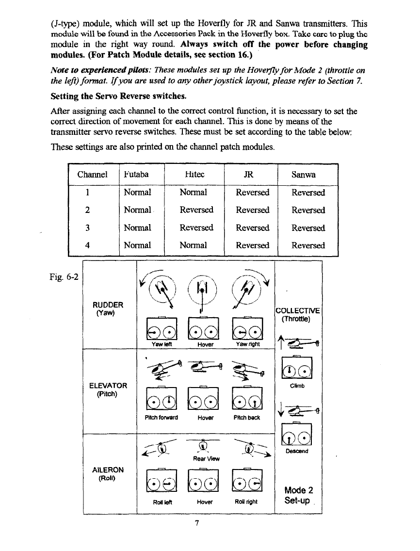
The Hoverfly has four flight control functions, Collective, Elevator, Aileron and
Rudder. Eachof thesewill be associatedwith one of the four axesof joystick movement
provided on the transmitter (Fig 6-2). The position of eachjoystick at any moment is
sent to the ECP by means of four seperatetransmitter channels, one for each flight
control function. On any transmitter, these will always be the first four channels,
regardless of the total number of channels the transmitter has. In a traditional
radio-controlled helicopter, these channelsemerge from the radio receiver on separate
sockets,to which the control servosare connected.It is of courseimportant to connect
each servoto the correct channel, sothat eachaircraft control surfaceis moved by the
correctjoystick.
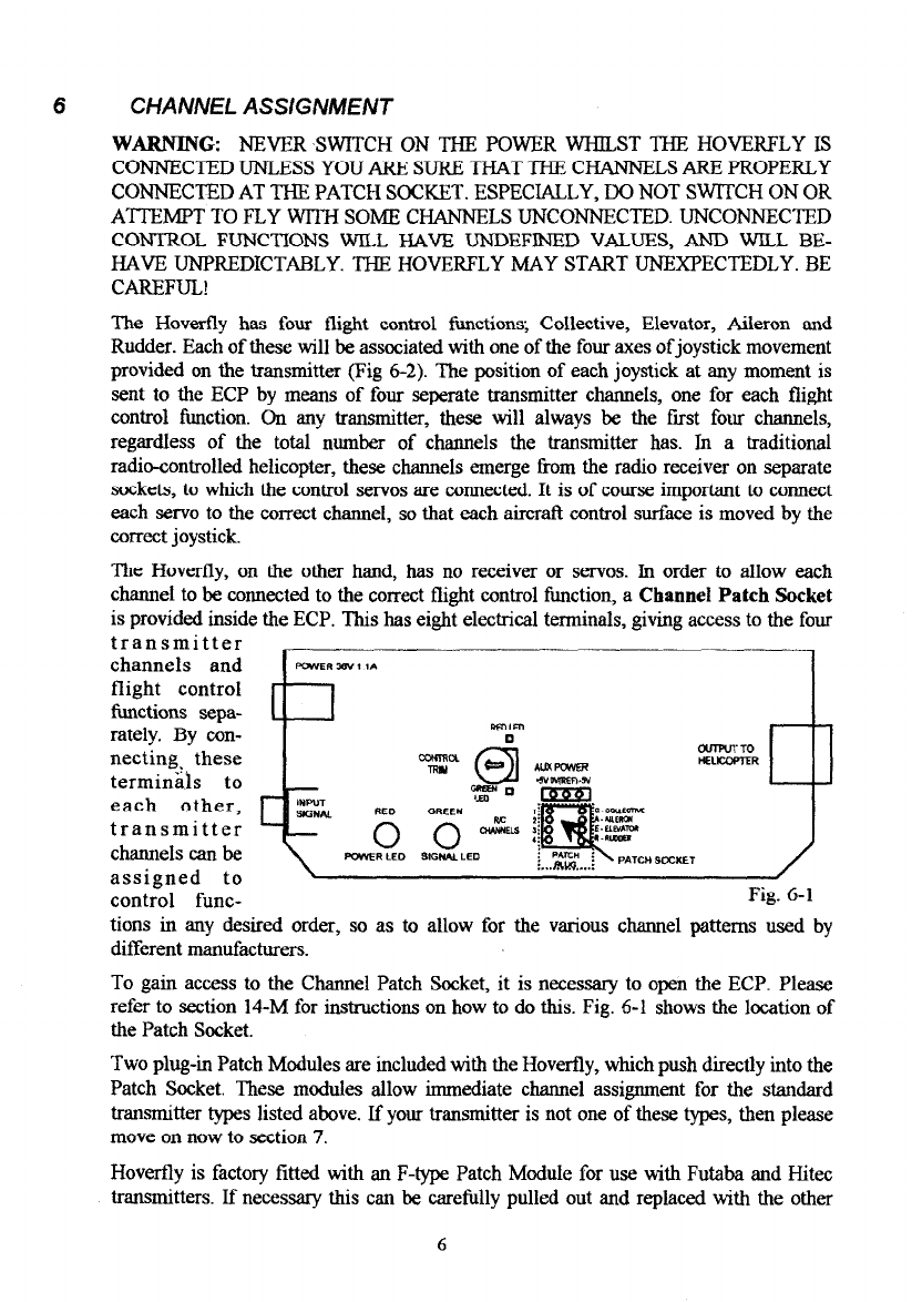
The Hovertly, on the other hand, has no receiver or servos. In order to allow each
charmeito be connected to the correctflight control function, a
Channel Patch Socket
is provided inside the ECP.This haseight electrical terminals, giving accessto the four
transmitter
channels and
flight control
functions sepa-
rately. By con-
necting. these
terminals to
each other,
transmitter
channelscanbe
assigned to
control func- Fig. 6-l
tions in any desired order, so as to allow for the various channel patterns used by
different manufacturers.
To gain accessto the Channel Patch Socket,it is necessaryto open the ECP. Please
refer to section 14-M for instructions on how to do this. Fig. 6-l showsthe location of
the PatchSocket.
Two plug-in PatchModules areincluded with the Hoverfly, which pushdirectly into the
Patch Socket. These modules allow immediate channel assigmnent for the standard
transmitter typeslisted above. If your transmitter is not one of thesetypes, then please
move on now to section7.
Hoverfly is factory fitted with an F-type PatchModule for use with Futaba and Hitec
transmitters. If necessarythis can be carefully pulled out and replaced with the other
6
(J-type) module, which will set up the Hoverfly for JR and Sanwa transmitters. This
module will be found in the AccessoriesPackin the Hoverfly box. Take careto plug the
module in
the
right way round.
Always switch off the power before changing
modules. (For Patch Module details, see section 16.)
Note to experienced pilo& These modules set up the Hovefly for Mode 2 (throttle on
the lef,) format.
If
you are used to any other joystick iayout, please refer to section 7.
Setting the Servo Reverse switches.
After assigning eachchannelto the correct control function, it isnecessaryto setthe
correctdirection of movement for eachchannel. This is doneby meansof the
transmitter servoreverseswitches.Thesemust be setaccordingto the table below:
These settingsare alsoprinted on the channel patch modules.
Channel
Futaba H&c JR Sanwa
1 Normal Normal Reversed Reversed
2
Normal Reversed Reversed Reversed
3
Normal Reversed Reversed Reversed
4 Normal Normal Reversed Reversed
Fig. 6-Z
RUDDER
(Yaw)

7. NON-STANDARD TRANSMITTERS
ASSIGNING CHANNELS
SETTING THE TRANSMITTER SERVO REVERSE SWITCHES
(You may skipthis section if you areusing a standardtransmitter.)
If your transmitter is not one of the standard typesfor which the PatchModules can be
used, it will be necessaryto determine the correct channel assignmentsand to patch
them manually. Fortunately, the ECP has facilities which make this process fairly
straightforward. In addition, if you wish to useajoystick layout other than Mode 2, then
this procedurewill allow you to set up the Hoverfly in the manner you wish.
The AccessoriesPackcontains four short lengths of black wire, which will be used to
connect the PatchSocketterminals in the required combination for correct operation.
They will be usedto link the transmitter channel terminals, which are in a row on the
left sideof the PatchSocket(Fig 6-l), to the flight control function terminals, which are
on the right sideof the PatchSocket.The wires canbe crossedover oneanother, sothat
anychannel canbe connectedto any flight control function.
To help determine which channel to assignto each flight control function, there are two
small indicator LEDs, one located on eachside of the Control Trim Adjuster (Fig 6-l).
TheseLEDs areconnectedto the Rudder (R) terminal, and light up to indicate when the
rudder control is moved. When the rudder is driven to the left, the red LED will light.
When the rudder isdriven to the right, the green LED will light.
Using theseLEDs, it iseasyto determine which transmitter channelis associatedwith a
particular joystick axis of movement. Having done so, this channel can then be
connected to the desired flight control function terminal, so that this function will be
controlled by the chosenjoystick axis.The procedure is asfollows:
(ALWAYS SWITCH OFF THE POWER WHILST CHANGING PATCH SOCKET
CONNECTIONS. TAKE GREAT CARE WHEN THE POWER IS ON, BECAUSE
DAMAGE TO THE ELECTRONICS CAN EASILY OCCUR IF ANYTHING METAL
TOUCHES THE CIRCUIT BOARD OR COMPONENTS.)
Channel patching and reversing switch setting.
Remove the factory fitted patch module from the patch socket.
Connect up asshown
in
Fig 5-1.
Do not connect the Hoverfly command lead yet. Do
not switch on yet.
Centre the ECPcontrol trim adjuster.
A. Patch channel 1 to the rudder terminal (R). Switch on.
B. Move eachjoystick in turn from end to end and note which axis operatesthe LEDs.
C. Use the table below to determine the correctsetting for the transmitter reversingswitch.
Switch off.
D. Re-patchchannel 1to the desiredfunction for thisjoystick (i.e from 1,to C,A,E or R).
Note: if R isthe desiredfunction for channel 1, removethe patch link sothat the rudder
function is available for the remainder of the tests. Fit this link at the end of the
procedure.
8

Repeat stepsA to D for channels2,3 and 4.
All thejoysticks are now connectedto the desiredcontrols on the helicopter,
Once the correct settings
have beendetermined, you
should record them for f&
ture reference. Blank
patch diagrams are in-
cluded in section 16 for
this purpose.
Stick Direction Function LED
Collective Forward Increase Red
Backward Decrease Green
Aileron Left Left Red
Right Right
Elevator Forward Nose down Red
1 Back 1 Nose up ) Green
Rudder Left
Right Lefl
Right Red
Green
8. Seffjng Control Prims (Neutral Positions).
The fmal adjustment required is to set the control trim, so that each function is at
neutral when the joysticks are centred. There is a single adjustment inside the ECPfor
this purpose, which setsthe trim coarselyfor all four channelsat the sametime.
To set this control, the equipment should
be
connected up
as in
Fig 5-1,
with the
exception of the Hovertly itself which should not be connected at this time. When
everything is connectedup, switch on the transmitter and the power to the ECP.After a
couple of seconds,both indicator lights should be lit. Extra careshould be taken from
now on, becausethe ECP isopen, and its electronics caneasilybe damaged if anything
metal touchesthe circuit board whilst the power
is
on.
The trim control is locatedcloseto the Channel PatchSocket(Fig 6-l). Next to it on the
circuit board are two small indicator LEDs, one of which will probably be lit. Before
setting the control, ensure that all the transmitter joysticks and trim adjusters are
centred, including the collective control, which doesnot self-centre.Now, using asmall
screwdriver, slowly tnrn the ECP trim control in the direction of the indicator light that
is lit. While turning the control, at somepoint the light will goout. The other light will
come on if the control is turned forther still. At the correct setting, both lights will be
off. (If there isno resonseTom the control, checkthat the transmitter is switchedon and
properly connected).
At this stage,the whole set-up can be checkedby moving the rudder control (left hand
joystick) from sideto side.As it ismoved left, the red trimmer LED should comeon. As
the stick is moved right, the green LED should come on. If this test fails, then all the
connections should be checkedcarefully, and the set-upprocedure done again.
If all is well, unplug the power from the ECP and stitch off the transmitter. Sinceali
settings arenow complete, the ECPcovershould becarefully replaced(Section 14-M).
9
9. BEFORE YOUR FIRST FLIGHT
Before attempting to fly the Hoveffly for the first time, it is veryimportant to familiatise
yourself with its controls and general behaviour. If you are an experienced pilot, we
suggestthat you do run through this section,in order to get to know the featuresunique
to the Hoverfly. This section also allows you to check that the Hoverfly is operating
properly before attempting a flight. New pilots should examine Fig 6-2 carefully, to
familiarise themselveswith the controls.
Connect up the equipment asin Fig 5-1. Turn on the transmitter, and set all the trim
tabs to their central positions. Setthe collective stickto zero,which will normally be in
the fully backposition. Plug in the power supply, but DO NOT turn on the mains yet.
Now pick up the Hoverfly, holding it by the green rotor hub disc,just below the central
dome. Your grip should feel firm but comfortable. Ensurethat nothing liesin the path of
the propellers, then switch on the mains.
The red light will illuminate on the ECP, followed by the green light afier about 2
seconds.The Hoverfly may give a momentary twitch, but if it doesmore than this, then
something iswrong. For example, the collective channel reverseswitch could be set the
wrong way, in which casethe Hoverfly would start up at full power! This is the reason
for caution the first time it is turned on. If the motors do start up, switch off the power
again and checkyour set-upscarefully.
NOTE: K&n switching 08 the Hovefly, AL, WAYS turn ofl the ECP power before the
transmitter. Some transmitters, especially older types, generate a random
signal
during
tim-ofl This signal can make the Hoverjly start up momentan’ly ifits power supply is
still
connected, possibly causing damage.
Ifall seemsto be well, it is time to try out the controls a little. While still holding the
Hoverfly, slowly advancethe collective stick. The main propellers should start to spin,
and the tail rotor may also turn. Adjust the rudder trim tab (below the left joystick) to
stop the tail rotor for the moment. DO NOT ALLOW THE TAIL ROTOR TO TURN
FAST FOR MORE THAN A FEW SECONDS OR MOTOR DAMAGE MAY
RESULT. Now keep advancingthe collective stick, and notice how the propellers speed
up. As they get faster, you will begin to feel their thrust. Advance the collective all the
way, listening to the sound created at different settings. You should not, however, let
the motors run at @ll power for longer than about 15 seconds.
Now back off the collective until the motors are running slowly. Hold the Hoveffly
horizontally, sothat the fuselage is free to steerbelow the rotor. Now move the rudder
trim tab to the left a couple of clicks, so that the tail rotor turns slowly. It should be
turning counter-clockwise when viewed from the left of the aircraft, and will now be
roughly trimmed for flight.
Now you cantry out the rudder control. Move the rudder stick slowlyto the let?.The tail
rotor will speedup, and the Hoverfly will start to steerto the left. If you pushthe stick
further to the left, the rate of steerwill increase, all the way to a rapid pirouette. Now
centre the stick again. Pushing the stick to the right will have a similar effect, except
that the tail rotor will reversedirection, steering the Hoverfly to the right.
If you have a gyro fitted try it out now to see how it works. With the main motors
running slowly, gently push the tail boom with one fmger, soasthe steerthe Hoverfly to
the right. The gyro will respond, speedingup the tail rotor in an attempt to prevent the
aircraft from turning. Pushingthe tail the other way will have a similar effect. Pushit a
little harder, and you will notice quite a firm effort against you. This is how the gyro
10

preventsrandom tail movements during flight. The aircraft will tend to remain pointing
in the samedirection, exceptwhen steeredby a pilot joystick command.
Having familiarised yourself with these controls, bring the collective back to zero. All
the propellers will stop, and the gyro will stop responding. Stand the Hovertly on the
floor in front of you. Advancethe collective stickjust alittle, until the propellers startto
rotate. Move it forwards a couplemore clicks,and the rotor should start to revolve. Do
not advancethe collective any further at the moment. The rotor should turn easily,and
will freewheel a little after the motors stop.Now try moving the rudder stick while the
Hoverfly is standing on the ground, main motors running slowly. If you have a gyro
fitted, you will notice that a verysmall amount of stick movement causesthe tail rotor
to run at full speed.This is becausethe stick movement acts as a
demand signal,
a
request to the gyro to make the aircraft steerat the selectedrate. The gyrothen attempts
to provide the requested rate of steer, by driving the tail rotor. Becausethe aircraft is
standing on the ground, it cannot move, and hence the gyro tries its best without
success!if you haveno gyro, the responseon the ground will be much like its response
in flight; the tail rotor will simply go faster the further you push the joystick.
You are now almost ready to attempt your first flight. However, in accordancewith
good flying practice, it is important to carryout a few pre-flight checks(Section 10).
ACCESSORIES FOR BEGINNERS
Large Fin
(appliesto model HlOOHoverfly, without gyro, only).
Hoverfly is difficult to control when fitted with the standard fin unless a yaw gyro is
installed (standard on model HlOl). A large fm is supplied to use instead of the
standard fin.
Preparethe fm by cutting round the printed outline and folded as illustrated alongside.
Fit it in placeof the standardfin - seesection 14-Jfor details of fm titting.
Trainer Undercarriage
To aid the stability at take-off and landing two black tubes are
supplied for forming a wide undercarriage.
Passone tube through the hole in the other to form a cross.Attach
this to the standardskidsusing adhesivetape.
Deflector Vanes
Three small vanes are supplied for attachment to the main
motors. The effect is to increasethe rotor speedand hence the
stability of the Hoverfly, making flying much easier for
beginners.
Cut out the vanesand attach them to the motors asshown:
Tuck the vanebetween the top of the motor andthe blackplastic
moulding asshown. Bend it down approximately 30 degrees(all
vanesshould be at the sameangle).
11
10 PRE-FLIGHT CHECKS
Before any flight, you should do the following:
a) Checkthat canopy,undercarriageandtailboom areall seatedsecurelyin place, and that
the tailfm is vertical. The boom canbe gently twisted to correct the latter.
b) Check that the Hovertly stands up straight on the ground. If not, gently adjust the
undercarriage. If the aircraft standscrooked, it will tend to topple over during take-off.
c) Check that the collective stick is fully back, then turn on the transmitter, then the
power. Bring up the collective slightly, checkthat all the motors run, and that the rotor
revolvesfreely. Move the rudder stickto ensurethat the tail rotor is operating.
In addition, after maintenance, a crash or a heavy landing, do the following:
d) Inspect the main motors to ensurethey are properly seated.
e) Checkthat the command line (inside the body) is securelyplugged in.
t) Check that the tail rotor retainer boss(the small plastic plug that holds the tail rotor
onto the drive pulley) is pushed fully home. This often comes loose in a crash,
preventing the tail rotor from being driven properly.
g) Hold the Hoverfly by the rotor hub, and advancethe collective a little. Move the rudder
stick, and check that the aircraft steers in the correct direction. Zncorred steering
liirection con be caused by incorrect bet%
f&g,
or by plugging in the tail motor
electrical connector the wrong way round Zf a gyro is
ftied,
a rapid pirouette will
result, because the gyro response will reinforce rather than counteract toil
movements.
It
is important tofind out about this before &tempting tofry?
Tip: Beginners frequently crash. To facilitate frequent pre-flight checks you may prefer to
fly without the canopy fitted. This is satisfactory if the tailboom is pushed 25mm
forward in its grommets to correct the balance
of
the Hovefly. (Remove the tailboom
completely from the chassis before attempting to move the grommets.)
11. YOUR FIRST FLIGHT
If you are a beginner, we strongly recommend that you read the whole of this section
before actually flying. If you are an experienced pilot, please read through the next’
couple of paragraphs,which outline take-off technique for the Hoverfly.
For your first flights, choosea room with asmuch unobstructed spaceaspossible. Do
not attempt to fly outdoors. Placethe Hoverfly on the floor, about 1.5 - 2 metres (say6
feet) from the ECPand facingaway from you. Positionyourselfjust behind the ECPand
make yourself comfortable. After a fina checkto ensurethe command line will not snag
on the undercarriage or foul the tail, advancethe collective about one quarter. Wait
while the rotor gets up speed,then continue to advancethe collective slowly, to just
12

below the half-way position. Allow time for the rotor to speedup while doing this. THIS
IS VITAL. The Hoverfly will blast off instantly if you advancethe collectivefar enough,
but it will be unstable and impossible to control until the rotor is up to speed.
When rewed-up and ready,advancethe collectivesmartly to achievelift-off. With most
transmitters, the Hovertly will leave the ground when the collective isjust abovethe
central position. It will be tempting to linger at this point, trying to hover an inchoff the
floor so asto prevent damage if you crash.Even experienced helicopter pilots do this!
Unfortunately, the Hoverfly is
much
harder to control when this closeto the ground,
becauseof ground effect. It will tend to skitter acrossthe floor at high speed,until it
bumps into something. Be bolder, and give the collective a burst at take-off to get the
aircraft about 18 inches off the floor straight away. Be ready to reduce the collective
almost immediately to prevent the Hoverfly hitting the ceiling! Learning how to do this,
so as to leave to the ground, reach a safe height, and then to hold it there requires
practice. Fortunately, the Hoverfly is robust,and will withstand alot of bumping about.
Once in the air, it will immediately become apparent that the Hovertly does not stay
there by itself In addition to controlhng the height, you must learn how to use the
rudder control to keep it pointing in the direction you want, which will generally be
away from you. At the sametime, you also haveto learn to use the all-important cyclic
controls, which allow you to guide the aircraft in the air or to keep it hovering in one
place. The cycliccontrolsare operated by the right handjoystick (mode 2). Moving this
stick will causethe Hovertly to tilt in the direction of stick movement, which in turn
will causeit to move in that direction, quickly! To keep it hovering, you must learn to
use this joystick to compensate for the aircraft’srandom movements. It is a little like
balancing a broom handle on your hand, though unfortunately, rather harder to learn.
The most common problem is one of over-control, followed by over-compensation,and
so on. The result is a furious oscillation, ending in a crash.Be gentle on the controls.
Small movements are all that are required to hover.
The cycliccontrols operate in relation to the aircraft itself. This meansthat the aircraft
will tilt towards
its
lefi when the cyclicjoystick ispushed to the left, etc.This gets very
confusing when the Hovefiy is facing you, or nose-in. This is why it is important to
learn to keep the aircraft pointing awayffom you asearly aspossible.Nose-in flying can
wait until you have learned the basics.
Learning to fly will be much easierat the start if you canhavean experiencedpilot help
you. In particular, your helper will be able to trim the Hoverfly accurately,sothat the
controls are all truly at neutral when the joysticks are centred. The set-up procedure
trims the aircraft well enough to fly, but it is only approximate. A well-trimmed aircraft
is easierto learn on.
Now practice, practice, and practice. Have fun, and Good Luck!
Note: Balance the rotorfor smootherjlight - see section 14F.
Care of the command line - section 14L, and routine maintenance - section 14G.
13

12. HELICOPTER PtWCIPLES
Conventional helicopters generatelift bymeans of the rapidly moving rotor blades. The blades
are shaped asaerofoils, and give the machine it’s name; ‘helico’, meaning rotary, and ‘pter’,
meaning wing. The bladesare setat an angleto the horizontal, sothat they createthrust asthey
turn, like a giant propeller. The angle of inclination of the blades is referred to astheir pitch,
and canbe changed by the pilot using the helicopter’s flight controls. Overall lift is controlled
by changing the pitch of all the blades simultaneously.This is referred to ascollective control,
and allows the pilot to causethe aircraft to climb or descend.
Directional control is achieved by varying the pitch of each blade as it travels around its
circularpath, sothat more lift isprovided on onesideof the rotor discthan on the other. This is
referred to ascycliccontrol, and allows the pilot to tilt the aircraft in any desired direction. For
example, in order to make the helicopter tilt forwards (as if to dive), the pitch of each blade
will be reduced asit enters the front semicircle,and increasedasit enters the rear semicircle.
More lift will then be generated at the rearthan at the front, causing an imbalance which tilts
the whole aircraft. As this happens, the aircraft will begin to move forwards, because the
overall lit? force is no longer acting straightupwards, but is inclined towards the front. This is
how a helicopter achievesforward flight. The controls of a helicopter allow the pilot to tilt the
aircraft from sideto side(roll) aswell asfrom front to back(pitch), and any combination of the
two, giving total freedom of movement. Constant adjustment of thesecontrols allows the pilot
to keep the machine exactly horizontal, andthus to hover. The mechanism that achievesthese
control functions is complex, and involves numerous mechanical linkages and push-rods, as
well as a special.tiltable bearing called the swash-plate. In the case of models, servosare
needed in addition, to provide physicalactuation of the control mechanisms.
It isimportant to realize that ahelicopter doesnot hover or fly by itself, but requirescontinuous
adjustment of the controls to keep it in a stable attitude in the air, and at the desiredheight.
The skill required to do this has to be learned, and is hnnlamental to helicopter flying.
However, a helicopter derivesa good deal of stability Tom the rotating blades, which act asa
giant gyroscope.This slowsdown its rate of responseto a speedat which a human pilot can
control it, with practice!
The rotor of a helicopter isgenerally driven by an engine mounted in the fuselage,by meansof
a large central drive-shaft. In order to make the rotor turn, the engine has to push against its
mountings. This means that the engine isactually trying to turn the helicopter fuselagejust as
hard as it is turning the rotor itself. This unwanted turning force is referred to as a ‘torque
reaction’. In order to prevent the fuselagefrom spinning, a helicopter is fitted with a tail rotor,
which is simply a propeller mounted sidewayson the tip of the tail, which pulls against the
tnming force from the engine. The tail rotor thrust can be changed, by varying the pitch of its
blades. This control allows the pilot to steer the aircraft in the horizontal plane, an action
referred to as ‘yaw’. It has a similar effect asthe rudder on a ship, except that it works even
when the aircraft is stationary in the air.
Learning to use this control to keep the helicopter pointing in a desired direction is a further
challenge for a new pilot. It hasto be done whilst at the sametime keeping control over the
other axesof movement, which requiresgreat concentrationfor a beginner. Becausethe pilot of
a model is not actually inside the aircratt, contusion tends to result when the machine is
pointing towards him/her. The aircratt’s left hand sidebecomesthe pilot’s right hand side, and
vice versa.The pilot hasto be constantlyaware of this in order to remain in control.
14
13. OVERVIEW OF THE HOVERFLY
The Hovertly usesa radically new approachto generate litt and control,
to achievea flight performance which closelyresemblesreal helicopters
and conventional radio controlled models. It is very lightweight, and
employs an extremely slow rotor speed,making it verysafe,and ideal for
indoor operation.
Unlike a conventional helicopter, the Hovertly uses small rotor-tip
propellers to generate its lift. Each propeller is driven by a separate
motor, and the main rotor turns only for the sakeof stability, driven by
the propellers. This approach has a number of advantages over
conventional designs:
1) The propeller speeds can respond very rapidly to changes in the
electrical supply. This allows cyclic control to be provided by changing
the propeller speedsat the appropriate moments during eachrevoluton of
the main rotor. This is a purely electrical function, not requiring any
mechanics;the need for a swashplate and servosis entirely eliminated.
The result is an extremely small, lightweight and mechanically simple
aircraft.
2) A large proportion of the aircraft massis in the 3 motors, mounted at
the rotor tips. This large rotating mass makes the aircraft very stable,
even at low rotor speeds. The stability mimics much larger models
effectively, while the low rotor speed makes the model comparatively
safe, and gives arealistic ‘scale’ appearancein flight.
3) The drive that turns the main rotor is provided by the tip mounted
propellers, rather than from within the fuselage. There is consequently
no torque reaction created, which allows the tail rotor to be very simple
and low-powered. The tail rotor provided on the Hoverfly isa fixed-pitch
propeller and is needed only for yaw control (steering). It turns in either
direction, to allow for both directions of yaw.
15

74. MAINTENANCE
Note: Tail rotor maintenance should be done after everytwo hoursflying - see14G.
A. DISASSEMBLY
1. Pull off the plastic dome Tom the rotor shaft.
2. Slide the rotor retaining spring off the rotor shaft. This may be quite tight, but it canbc
levered up from the rotor hub by straddling the shaftjust below it with the blades of a
small pair of scissors.Twisting the spring against the direction of the coils will also
loosen it during withdrawal. Be careful not to lose it!
3. Carefully lift off the rotor.
4. The bottom lip of the canopyis pulled in at the front by a plastic strap. This preventsthe
canopy from lifting off at the front. To remove the canopy, pull it gently off its foam
mounting at the top of the mainframe. Lift it over the shaft, and slideit forwards to clear
the yaw motor.
5. Remove the m&marriage by pulling it downwards out of the mainframe. The command
line passesthrough the undercarriage,so it has to be passedalong to the end in order to
free it.
6. Unplug the lead to the yaw motor (at the top of the mainframe).
7.
Push the boom downwards until the two mounting grommets are released from the
mainframe clips. Withdraw the boom carefully, guiding the yaw motor through the
main&me.
8. Unplug the command line connectorinside the mainframe.
B. BEASSEMBLY
This is basicallysteps 1to 8 above,in reverseorder. Payattention to the following:-
Step 8. One limb of the command line plug has a flat end. This carries a white spot,
which aligns to the white spot on the alignment lug at the edge of the socket.
Step
7. Before fitting the boom assembly,ensurethe grommets are correctly positioned.
They should lie just outside the white rings on the boom. The command line should pass
on the right hand sideof the boom. Ensurethe fm and yaw motor are upright (motor on
top of the boom, tail propeller on the left).
Step6. The yaw motor connectorplug carriesawhite spot,which aligns to the white spot
on the socket.
Step5. When fitting the undercarriage,passthe command line through the loop between
the crosswiresand the right hand skid.
Step 4.
When fitting the canopy, engagethe front first, then easethe top over the shaft
and onto the mainframe foam mounting.
Step
3. Fitting the rotor requires somecareto ensurethat the commutator brushesdo not
get damaged. Slide the rotor onto the shaft, manoeuvring it sothat the three brushes lie
against the shaft symmetrically. Ensurethat the upper brush is on the correct side of the
16

shaft asthe rotor is lowered. Do not allow the rotor to seatfully until the three brushes
have been litled on to the commutator. Use a small hook (the head of an ordinary pin
will do) to lift eachbrush on to the commutator. (Do not over-bend the brush wires in
doing this.) When all the brushesare in place, allow the rotor to fall fully into place.
C.
1.
2.
3.
4.
D.
1.
2.
3.
E.
F.
Step 2. Lift the upper brush onto the retaining spring as it is fitted. Do not push the
retaining spring too hard onto the top of the rotor. The rotor must rotate freely. We
recommend leaving about 0.25mm clearance.
MAIN MOTOR REPLACEMENT
Do not attempt to do this unlessyou areconfident of your solderingability.
Unsolder the two wires from the motor terminals using an iron with a small tip.
Pull off the push-fit propeller. (Seesection E below)
Lift the top of the plastic bracket off the upper motor boss,and easeit over the shaft.
Gently prise the baseof the motor free from the bracket, and withdraw it upwards.
Fitting the motor is the reverseof the above. The outer plastic retaining band can be
bent out of the way during motor fitting, then replaced squarely round the side of the
motor afterwards. Ensure that the electrical terminal marked ‘MABUCHI’ is located
towards the centre of the rotor. The blue wire connects to this terminal. Carefully
re-solder both wires and dressthem against the rotor. .
ROTOR REPAIR
If the rotor isdamaged it isrecommended that the complete rotor assemblyis replaced.
However if a repair is attempted pay particular attention to the following, to minimise
aircraft wobble during flight.
The lateral tilt of the motor must be 5 degreescounter-clockwise when viewed towards
the centreof the rotor. Theradial tilt shouldbe minimal, but equal for all threemotors.
Ensure the integrity of the rotor plane ismaintained accurately.
Ensure that the length of eacharm (measured from the centreof the rotor to the motor
shaft) is identical for all three arms.
PROPELLER REMOVAL AND RE-FITTING
The propellers are a tight push-fit onto the motor shafts. To remove, the motor should
be.grasped at the sides between thumb and forefingers, so asto clamp the armature,
preventing the motor from turning. The propeller can now be twisted back and forth
whilst pulling it in order to remove it. Re-fitting is done in much the sameway, taking
care to offer it up to the motor shah assquarely aspossible.
WARNING: THE MOTORS MAY BE HOT AFTER RUNNING FOR SOME TIME.
BALANCING
Although the Hoverfly comesready to fly, flight performance can be improved by fine
balancing of the rotor and propellers. Balancing the rotor will reduce the amount of
aircraft ‘wobble’ experienced during flight, especially at hover. Balancing the
propellers will reduce noise and sympathetic buzzing from the airframe. It can also
17

increaseclimbout performance. A truly well balanced Hovertly will fly silky smooth,
and is a delight to watch. Balancing is straightforward, and is largely a matter of trial
and error. One of the great featuresof the Hovertly is its ability to fly when badly out of
balanceand trim, this allows for safeexperimentation.
Propeller Balancing: This is best done first, sinceit will have an influence on the rotor
balancing process.The propellers will bebalancedby applying small piecesof adhesive
1.
2.
3.
4.
5.
6.
tape to the blades. Theprocedure is asfollows:
Setup the Hovertly sothat it is readyto fly.
With the Hoverfly resting on the floor, hold it fnmly by one of the rotor arms, taking,
care to keep your fingers out of the way of the propeller. Now gently bring up the
collective to around hover speed.Listen to the sound, and note the amount of vibration
felt in the rotor arm. Now lower the collectiveto zero.
Using leftover tape from the decalstripes,cut apiece about 6mm squareand stick it to
one of the propeller blades on the arm you were holding. Position it centrally acrossthe
blade, about Smm from the tip.
Now repeat the above vibration test. It will generally be obvious straight away whether
you have improved or worsenedthe balance.
If the vibration hasincreased,simplymove the tapeto the other blade and try again. If it
has lessened ou should experiment a little with the position and sizeof the piece of
tape, to get ;il e best result. Moving the tape inwards will reduce.its effect, whilst
making it larger will increase the effect. A well balanced propeller will feel quite
smooth, and will not ‘buzz’ asit speedsup. Remember that somevibration will be felt
from the other, unbalanced propellers.Havin
you may want to move it to the undersideof t.ifound the right sizeandposition of tape,
e blade, out of sight.
This processcan be repeated for the other two propellers. Sincepropellers in the same
batch tend to be very similar, it is often good enough just to copy the first balance
solution.
NOTE: The tape supplied for the stripes is ideal, because it won ‘t ‘creep ’ when exposed
to the centrzfugal force
of
spinning. Other tapes will work, but many will gradually
move with use.
Rotor Balancing: If the Hoverfly wobbles in flight, this can be corrected b the careful
balancingof the rotor. The rotor will bebalancedbyadding small pieceso6 Blu Tat’ to
the endsof the arms.on atrial and errorbasis.The correctsolution is usuallvone of two
a>
b)
a>
b)
c>
d)
possibilities: ’
If one of the armsis a bit light, adding weight to it will fix the wobble.
If one of the arms is a bit heavy, adding weight to the other two arms will fix the
wobble.
Somepoints to note:
You will neverneed to add weight to all three arms.
When two weights are needed, they canusually be roughly equal.
The level of precision required is not very great. It really isn’t hard to make a big
difference!
Wobble is actually caused by several interrelated factors, which create a composite
effect which is addressed by adding weights. Dynamic imbalance is one of them.
However, wobble will also be caused by slight inaccuracies in motor alignment
(especially radial slant), distorted rotor geometry (don’t let the rotor get wet), and
chipped propellers. A wobble sometimesoccursafter a rebuild, due to imperfect carbon
18

brush contact.This will generally cureitself after a minute or two in the air.
If you are a beginner, or if you fly wild and crasha lot, it really isn’t worth being too
fussy. You could buy a secondrotor, for specialoccasions!
The balancingprocedure is asfollows:
With apencil, number eachof the rotor arms for easyidentification.
Fly the Hovertly, and note the amount of wobble present.
Roll out a small ball of ‘Blu Tat’, 5-6mm in diameter. Stick it to the outer edge of
motor 1.
Fly the Hoverfly again. Note if the wobble hasimproved or worsened.
If the wobble hasworsened,try moving the ‘Blu Tat’ to motor 2 and try again, etc.
Once you’ve found the right motor, you can try adding weight to a secondmotor for
further improvement. It is otten best to divide the first weight in half between the two
motors.
You can also try different amounts of weight. 5-6mm diameter is a good start, but do
experiment.
When you arehappy with the balance,you canmove the ‘Blu Tat’ to the inside edgeof
the motor. The plastic bracket hasa convenient recessunder the rotor arm where it can
be hidden.
TAIL MAINTENANCE
Although robust, the tail mechanismdoes require regular maintenance in order to keep
it working well. It will experience heavy use and rapid speedchanges?especiallyif a
gyro is used.In particular, the belt isprone to wear. In-flight tail rotor farlureswill often
lead to a crash; therefore, we recommend the following after every two hours flying
time:
Remove the undercarriage, unplug the yaw motor (this canbe reached with the canopy
in place,just!), and unclip the tailboom from the mainframe. Remove it completely.
Using a pointed tool, unhook the belt from the motor pulley, and remove it fiorn the
other end.
Check that both rear pulleys turn freely, and apply a tiny amount of light vegetable oil
to the bearing area, between eachpulley and the bracket. Use a scalpelblade or similar
tool. Remove the tail propeller by prising out its retaining plug. Apply a small drop of
oil next to the top of the bearing pin inside the
care not to get oil in the pulley grooves,and caret!l
ropeller mounting turret. Take great
Ily remove anythat does.
The belt can be re-used once. Before replacement, it should be thoroughly powdered
with talc. Sprinkle some into a dish, and rub the belt around in it. At every second
overhaul, the belt should be renewed.
Re-insert the belt (seeH below).
Re-assemblethe Hoverfly, and test the tail before flying. Especially, ensure that the
direction is correct.(SeeFig 14-I)
e>
1.
2.
3.
4.
5.
6.
7.
8.
6.
1.
2.
3.
4.
5.
6.
Note: Never run the tail motor unloaded (without the belt and propeller fitted).
Over-revving and damage may result.
Tip: After a while, especial& in warm conditions, the tailboom may droop. This can be
cured by twisting it through 180 degrees. Having done so, turn the end
fittings
around
19
also, so that the whole tail unit becomes inverted. Take care to rotate the ends the same
way, to avoid twisting the belt.
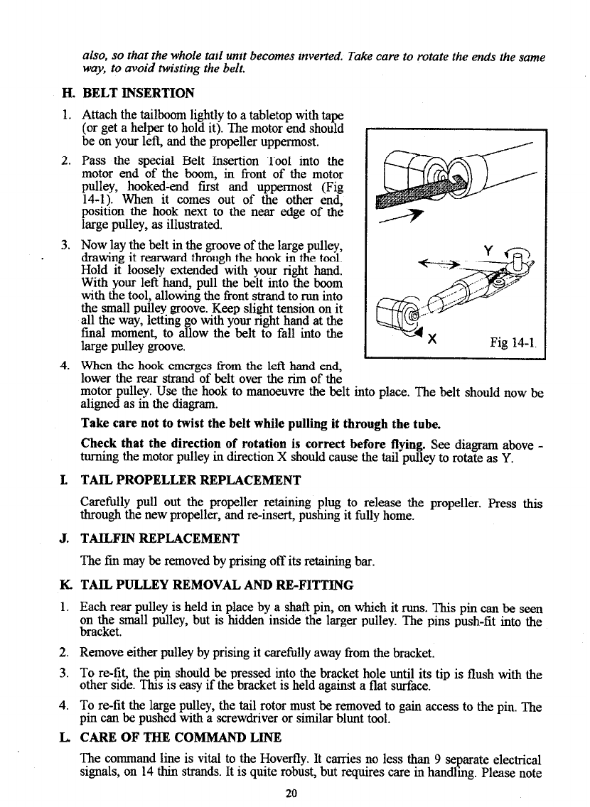
H. BELT INSERTION
1. Attach the tailboom lightly to atabletop with tape
(or get a helper to hold it). The motor end should
be on your left, and the propeller uppermost.
2. Pass the special Belt Insertion Tool into the
motor end of the boom, in front of the motor
pulley, hooked-end first and uppermost (Fig
14-1). When it comes out of the other end,
position the hook next to the near edge of the
large pulley, asillustrated.
3. Now laythe belt in the grooveof the large pulley,
drawing it rearward through the hook in the tool.
Hold it loosely extended with your right hand.
With your left hand, pull the belt into the boom
with the tool, allowmg the front strand to run into
the small pulley groove. Keep slight tension on it
all the way, letting
final moment, to P
o with your right hand at the
alow the belt to fall into the
large pulley groove.
4. When the hook emergesfrom the lett hand end,
_.
lower the rear strand of belt over the rim of the
motor pulley. Use the hook to manoeuvre the belt into place. The belt should now be
aligned asin the diagram.
Take care not to twist the belt while pulling it through the tube.
Check that the direction of rotation is correct before flying.
See diagram above -
turning the motor pulley in direction X should causethe tail pulley to rotate asY.
L TAIL PROPELLER REPLACEMENT
Carefully pull out the propeller retaining plug to release the propeller. Pressthis
through the new propeller, and re-insert, pushing it fully home.
J. TAILFIN REPLACEMENT
The fm may be removed by prising off its retaining bar.
K. TAIL PULLEY REMOVAL AND RI&FITTING
1. Each rear pulley is held in place by a shat?pin, on which it runs. This pm canbe seen
on the small pulley, but is hidden inside the larger pulley. The pins push-fit into the
bracket.
2. Remove either pulley by prising it carefully away from the bracket.
3. To re-tit, the pin should be pressedinto the bracket hole until its tip is flush with the
other side. This is easyif the bracket isheld against a flat surface.
4. To re-tit the large pulley, the tail rotor must be removed to gain accessto the pm. The
pin can be pushedwith a screwdriveror similar blunt tool.
L CARE OF THE COMMAND LINE
The command line is vital to the Hoverfly. It carries no lessthan 9 separateelectrical
signals,on 14tbm strands.It isquite robust, but requires carein handlmg. Pleasenote
20
Other manuals for Hoverfly
1
Table of contents
Other Snelflight Toy manuals


Popular Toy manuals by other brands

Our Generation
Our Generation Let it Roll! Bowling Alley instructions

Oliver Flugmodellbau
Oliver Flugmodellbau FRESH Construction manual

AquaCraft
AquaCraft Rescue17 instruction manual

Goldwing RC
Goldwing RC Electric Extreme YAK55M 70E manual

REVELL
REVELL HMMWV M966 TOW Missile Carrier Assembly manual

General Hobby
General Hobby Ultimate manual

Phoenix Model
Phoenix Model YAK54 YAKOVLEV instruction manual

NOCH
NOCH 14620 manual

Carson
Carson Sea Shark FD instruction manual

Mega Construx
Mega Construx PRO BUILDERS HALO GLB56 quick start guide

Fisher-Price
Fisher-Price T6339 instruction sheet

Mattel
Mattel Disney Pixar TS3 BUZZ SAVES TRAIN instructions


