Snelflight chinook Instructions for use
1

INTRODUCTION
Congratulations on purchasing your Snelflight Chinook helicopter. The
model is the smallest twin rotor model helicopter produced, yet it has a
realistic appearance and sound during flight.
Our unique and patented Electrocyclic control system gives the model an
unmatched combination of performance and mechanical simplicity. Since
it is mains powered it can fly continuously and, best of all, it comes ready to
fly, right out of the box.
The only setting up needed is the adjustment of your transmitter's settings,
where required. Although not strictly a beginner's model, the Snelflight
Chinook is surprisingly rugged and easy to fly. However we strongly
suggest that you take the time to read this manual carefully before your
first flight, as the aircraft behaves a little differently from other model
helicopters.
IMPORTANT NOTICE
This product is not a toy. It is an engineered model which
although light in weight is capable of causing damage or injury
if operated irresponsibly, primarily due to contact with the six
thrust propellers. Avoid flying close to people or pets.
It may start up violently if the instructions contained in this
manual are not followed, or if a fault occurs. To be sure of
avoiding damage or injury always hold the aircraft firmly by
grasping the sides of the rear rotor tower (keeping clear of the
propellers) when switching on the mains power.
The motors become hot in use; to avoid injury do not touch
until cool.
Unplug from the mains supply when not in use. Do not use in
the wet.
2

CONTENTS
1. Introduction
2. Packing List
3. Transmitter Requirement
4. Handling the Model
5. Transmitter Set-Up
6. Preparing for Flight
7. Your First Flight
8. Principles of Operation
9. Maintenance
10. Specifications
2. PACKING LIST
This Manual:
The Helicopter:
Power Adapter (with
detachable cord):
Signal Lead:
Decals:
Transmitter (if supplied):
Pencil:
Please read it carefully before flying the
model.
It comes with its thin command line already
attached.
This converts power from the wall into 36V
d.c. to power the model.
This is used to connect the model to a
suitable R/C transmitter. It is suitable for JR
transmitters, as well as the transmitter sup-
plied with the model (if applicable). Leads for
other transmitter types are available from
Snelflight.
For you to customise your model.
Handset to control the model. It requires 8
AA batteries.
For applying graphite lubricant to the rotor
brush slip-rings.
3. TRANSMITTER REQUIREMENT
Unless you purchased your model with transmitter included, you will need
your own transmitter to fly the Chinook helicopter. The model is designed
to operate with the following types:
FUTABA JR HITEC MULTIPLEX
3

Some Sanwa transmitters will also work, but please note that the newer
types with 5-pin trainer socket are not at present supported. The
transmitter you use will need to meet the following minimum features:
Minimum transmitter specification
zFour control channels with two twin-axis joysticks.
zFitted with a trainer (buddy box) socket, using PPM (pulse
position modulation) signalling.
zReversing switches on at least the first four channels.
Since the transmitter connects to the model by wire, frequency and
transmission type (AM or FM) do not matter.
The signal lead included with the model is suitable for JR transmitters only.
Please see your dealer or contact Snelflight to obtain leads for the other
types.
4. HANDLING THE MODEL
The Chinook should be held by the rotor centres, grasping them from
above by the green printed circuit discs immediately below the hubs (Photo
1). Alternatively, it can be held by firmly grasping the sides of the rear rotor
tower (Photo 2). On no account should it be picked up by the body.
Carefully lift the helicopter out of the box and place it on the floor.
Uncoil the command line, guiding it away from the model rearwards,
ensuring that it doesn't get hung up on the wheel axles.
Photos 1 and 2: How to hold the Model
1 2
4

5. TRANSMITTER SET-UP
If you are using the transmitter included with the model, it will have been
preset ready for use and you may skip this section. If you are using your
own transmitter, you should follow these steps carefully.
a) Switch your transmitter into training (buddy box) mode: In this mode, your
transmitter will send a signal to the trainer socket, but will not transmit from the
antenna. This greatly extends transmitter battery life, and eliminates interfer-
ence problems. On some radios, training mode is selected simply by inserting
the training plug into the socket. JR transmitters typically work this way. If this
is the case, the main power switch must be left in the OFF position. On other
units the power switch must be set to ON, but the crystal should be removed to
prevent radio transmission.
b) Signal Mode Selection: The Chinook requires PPM signalling, so if your
transmitter offers PCM as well, it must be switched to PPM. Most inexpensive
non-computer radios are PPM only, so this setting is not necessary. PCM-only
transmitters cannot be used, but these are fortunately very rare.
c) Servo Reverse Switches: These should be set according to the table below:
d) Servo Travel: If your transmitter has adjustable servo travels (endpoint
adjustments), set the first four channels to 100% in both directions of throw.
Exponential joystick response can be selected if you wish.
e) Channel Centres: If your transmitter has channel centre adjustments, these
should be set to zero (centred) on the first four channels. The external trim tabs
should also be centred.
f) Mixing Functions: If your transmitter has mixing functions such as Throttle to
Rudder mixing, these should be switched off, or set to zero.
g) Throttle Curve: If your transmitter has a throttle curve feature, it should be set
up to give a full range, linear throttle response. Make sure that the Throttle Hold
switch is turned off. Some transmitters have an Aeroplane mode, in which
these functions are omitted. It is usually easier to use this mode with the
Chinook.
1 2 3 4
Futaba
Hitec
JR
Multiplex
Normal
Normal
Reversed
Reversed
Normal
Reversed
Reversed
Reversed
Normal
Reversed
Reversed
Reversed
Normal
Normal
Reversed
Reversed
Channel >>
5

6. PREPARING FOR FLIGHT
Before flying the model, you should carry out the following procedure:
a) Stand the helicopter on the floor, facing away from you. Feed the command
line rearwards, ensuring that it doesn't catch on the wheel axles.
b) Connect the power adapter to the wall, and plug its 2.1mm output jack into the
matching socket at the bottom end of the command line. The helicopter's white
searchlight should illuminate, under the nose. You should now wait about 3
seconds before touching the aircraft, to allow the onboard heading-lock gyro to
self-calibrate.
c) Connect the signal cord to the transmitter and switch on (if necessary). Ensure
that the throttle stick is set to minimum.
d) Now connect the other end of the signal cord to the matching phono socket on
the command line. WHILST DOING THIS, HOLD THE AIRCRAFT FIRMLY BY
THE SIDES OF THE REAR ROTOR TOWER (PHOTO 2) IN CASE IT STARTS
SUDDENLY. KEEP CLEAR OF THE PROPELLERS!
e) During the next two seconds, the helicopter will configure itself to the type of
transmitter being used. The correct channel order will be set (this varies
between brands), and each control's zero position will be set to match the state
of the relevant channel. It is important not to move the joysticks during this
process.
f) If all is well, the helicopter's red & green navigation lights will start to blink. If
they don't, please read the suggestions in the panel below.
After maintenance, a crash or a heavy landing, please check the following:
g) Check that the aircraft canopy is properly seated below each rotor.
h) Inspect the motors to ensure they are properly seated in their plastic brackets.
If the navigation lights don't start to blink: Something is wrong. The
problem will usually be caused by one of the following:
1) No signal from transmitter: Ensure that the lead is properly connected at each end,
and that the power switch is in the required position (Section 5a).
2) Transmitter in PCM mode: The transmitter must be set to PPM mode.
3) Throttle not at zero: To prevent accidents, the helicopter won't start if the throttle
stick is above minimum. This will be the case if the reverse switch is set incorrectly
(see table in Section 5). On computer radios, incorrect setting of throttle travel or the
throttle curve can also cause this problem. The throttle needs to be set to give a
linear, +/-100% output, as on a basic transmitter.
4) Wrong type of transmitter: Please see Section 3 for supported brands.
6

7. YOUR FIRST FLIGHT
If you are new to helicopters, we recommend that you gain experience on a
single rotor trainer such as the HoverflyHoverfly before flying the Chinook. Although
quite easy to fly, the Chinook is not intended for beginners. Experienced
pilots should read this section, since the Chinook behaves slightly
differently from other models.
For your first flights, choose a room with as much unobstructed space as
possible. Do not attempt to fly outdoors. Place the helicopter on the floor in
the centre of the available flying area, facing away from you. Position
yourself about a metre behind it. After a final check to ensure that the
command line will not snag on either wheel axle, begin to advance the
throttle (collective) gradually, allowing the rotors time to rev-up as you do
so. The motors will not all start simultaneously (please see the next section
for an explanation of why this is so), and as a result the helicopter will
shake slightly (just like the real thing!) whilst revving up. Keep raising the
throttle until the aircraft starts to seem light on its wheels; at this point the
throttle will be at roughly mid-stick. It should not take less than 5
seconds to reach this stage. Please note that it is crucial to give the
rotors time to speed up prior to take-off.
Once revved-up and ready, advance the throttle smartly for a decisive
lift-off. This is the easiest way to begin the first few flights. Once in the air
you will find that the aircraft is docile, with good heading-hold. Controls
should be made smoothly and early, since twin-rotor helicopters respond
more slowly than single-rotor types.
Very occasionally, you may wish to make small adjustments to aircraft trim
during flight, using the transmitter trim controls. If you do so, please be sure
to return the trims to centre before connecting the transmitter next time,
otherwise the helicopter will self-calibrate to the new trim settings, treating
these as the centre positions. You will then need to add even more trim to
restore correct flight. Most trim issues can be resolved without use of the
transmitter trims and this is preferable: Please see the Maintenance
section.
8. PRINCIPLES OF OPERATION
The Chinook generates the lift necessary for flight by means of the six
small, rapidly spinning rotor-tip propellers. The rotors themselves do not
provide any lift. The outboard positioning of the motors gives each rotor a
large moment of inertia, thereby imparting a high degree of gyroscopic
7

stability to the aircraft. At the same time, the rapid movement of the motors
through the air keeps them comparatively cool during operation.
Cyclic control is provided by varying the speeds of the motors as they
move around their circular path. For example, to provide a left-hand roll
force, the motors slow down as they enter the left-hand semicircle, and
speed up as they enter the right hand semicircle. This patented control
method requires no actuation servos and few moving parts, resulting in an
extremely small, lightweight and mechanically simple aircraft.
Uniquely, both the aircraft's rotors turn in the same direction. This is
possible because the rotors are driven by their on-board motors, rather
than by an engine mounted within the fuselage. There are therefore no
torque reactions produced. Furthermore the rotors have no mechanism for
tilting independently of each another; their gyroscopic behaviours are
therefore combined. If the rotors turned in opposite directions these
behaviours would cancel each other out, making the aircraft very unstable.
Owing to the large combined gyroscopic reaction from the two rotors, the
helicopter's attitude control inputs get shifted a full 90 degrees clockwise
during actuation. To make the aircraft pitch (forwards or backwards), a roll
force must be applied. This is done by operating the two rotors' roll cyclics
in unison. To make the aircraft roll, a pitch force must be applied. This is
done by changing the front and rear collective controls in opposition, i.e.
the overall lift of one rotor is increased while that of the other is reduced.
To make the aircraft yaw, the two rotors' roll cyclics are operated in
opposition. The two gyroscopic reactions try to pitch the aircraft in both
directions at once and as a result, the aircraft as a whole doesn't tilt.
Instead, the front rolls one way and the back rolls the other way! This
causes the fuselage to twist along its length; the airframe is designed to
allow this. In the twisted state, the two ends of the aircraft are pulled
sideways in opposite directions, resulting in a yaw motion.
Although there are no torque reactions from driving the rotors, bearing
friction does tend to turn the fuselage in a clockwise direction. To prevent
this, a continuous anticlockwise yaw input is required. This is provided by
the cyclic controls as described above, and is the reason why the aircraft's
propellers start at different instants as the throttle is raised from minimum.
8
9. MAINTENANCE
A. DISASSEMBLY
1) Remove the rotors. To remove a rotor:
a) Unplug the power cord from the command line.
b) Pull the black plastic dome off the shaft.
c) Carefully lift the rotor off, taking care not to bend the brushes on the underside
of the hub. Don't mix up the two rotors!
2) Lift off the helicopter body, carefully easing it over the slip-ring panels at
the base of each rotor shaft. The interior parts will now be fully revealed.
3) To remove the electronic circuit board, first unplug the two connectors.
Next, detach the board by cutting through the double-sided foam adhesive
along the top edge, using a sharp knife. The foam can then be peeled off.
B. REASSEMBLY
Reassembly is the reverse of disassembly. Please note the following:
a) When replacing the
body, take care to
position the navigation
lights.
b) When replacing each
black plastic dome, it
should push the rotor
down against spring
pressure from the
brushes. The correct
position is reached when
there is about 0.5mm of
clear shaft visible below
the circuit board disc
(Photo 3)
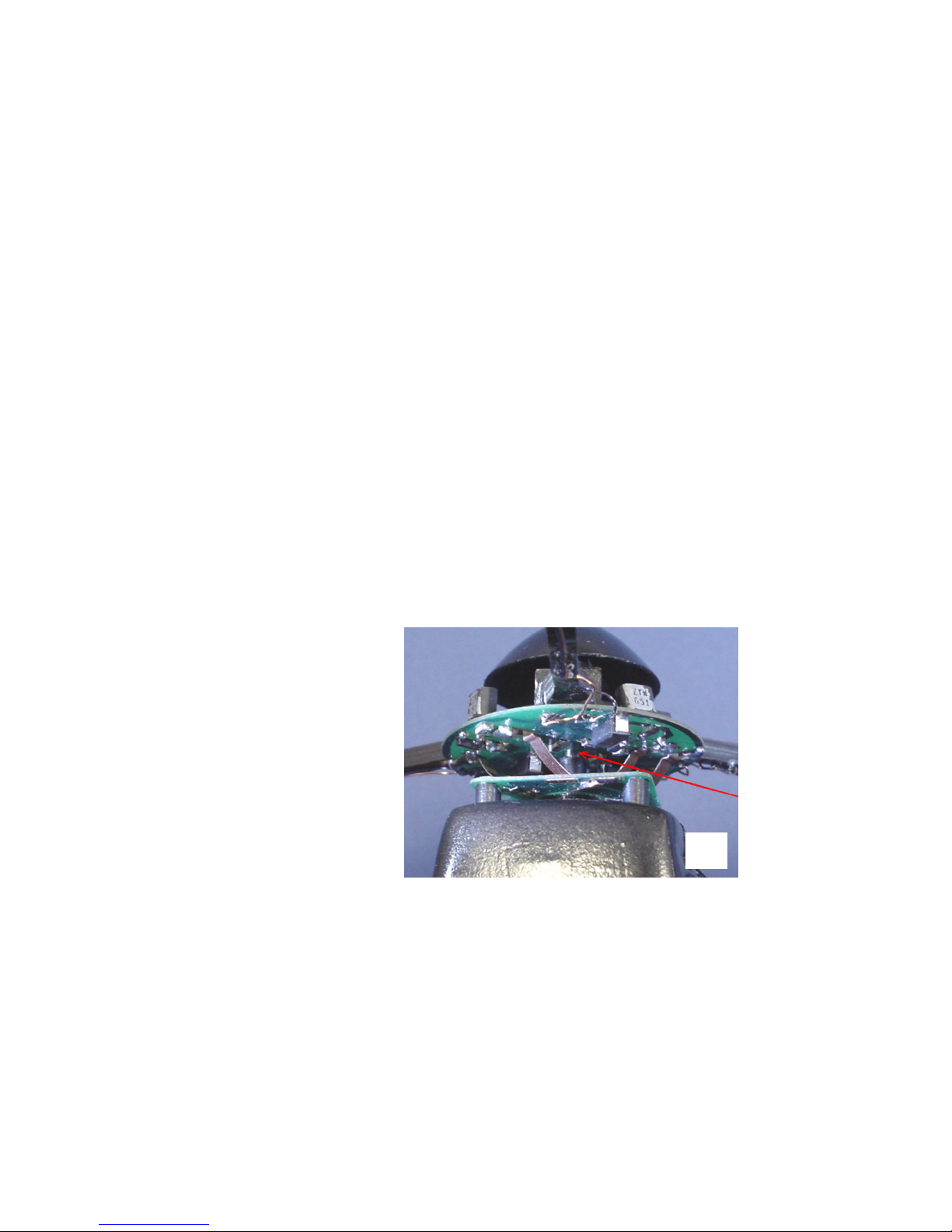
C: SLIP-RING LUBRICATION
Each rotor receives power to drive its motors via a system of slip-rings
etched onto a small circuit board at the base of the shaft. Brushes on the
rotor hub run on the slip-rings, and from time to time they need lubrication.
This is done by applying graphite (a good electrically conductive lubricant)
using an ordinary pencil. Please note the following:
Photo 3: Rotor Clearance
3
0.5mm
clearance
9

a) Always disconnect the power before lubrication.
b) The path of the brush contacts on each slip-ring can be clearly seen (Photo 4).
Apply graphite sparingly to these areas.
c) Take great care to avoid getting
graphite between the slip rings, as
it will create a short circuit.
Remove any that does get in the
cracks, using a cotton tip
dampened with alcohol or nail
polish remover. An eraser is also
quite effective!
d) Apply graphite very sparingly to
the innermost slip-ring.
e) Lubrication should be carried out
after every 3-4 hours of flight, or if
brush running noise increases
(spin the rotor by hand and listen).
D. AIRCRAFT TRIM
When the control signal is connected to the Chinook, the aircraft
automatically configures itself to suit the particular transmitter being used.
This process includes precise adjustment of electrical control trims, making
further trimming of the aircraft unnecessary most of the time. There are two
exceptions when it becomes necessary to make manual adjustments:
1) Yaw Trim: In order to prevent rotor bearing friction from causing an
unwanted yaw movement, the helicopter has a continuous anticlockwise
bias built into its yaw control electronics. This is generally successful in
producing a "neutral" yaw trim, but the electonics are unable to completely
compensate for variations in bearing friction caused by wear, and by
changes in atmospheric temperature and humidity. If the aircraft has a
tendency to drift either clockwise or anticlockwise, this can often be cured
by taking steps to alter the bearing friction deliberately:
a) If the aircraft is drifting clockwise (right-hand yaw), then there is too much
bearing friction. Friction can be reduced by lubricating the slip-rings, or
lubricating the rotor bearings with a tiny amount of light oil. Increasing the rotor
clearance (up to 1mm, see Photo 3) by lifting the black dome slightly, will also
reduce friction.
b) If the aircraft is drifting anticlockwise, then there is too little bearing friction.
This is rare. However friction can be increased if necessary by reducing the
rotor clearance.
Photo 4: Slip-ring Lubrication
4
10

2) Roll Trim: Owing to the large combined gyroscopic reaction from the
two rotors, the helicopter is very sensitive to any difference in lift between
the two rotors. Some difference is inevitable due to motor and propeller
performance tolerances, and if uncorrected it will give rise to a roll trim
error. Correction is done simply by adding a small weight to either the front
or the back of the aircraft body. The weight needed will generally be under
two grams, and a small ball of Blu-Tack is ideal. A new Chinook will often
have this correction applied during factory testing:- the weight will be just
inside the body at either the front or rear end of the underbelly opening.
This weight may need to be modified after propeller replacement, or if the
two rotors are interchanged. In the latter instance it is usually enough just to
transfer the weight from one end of the aircraft to the other.
1) If the aircraft rolls to the left: It is tail heavy. Add weight to the front, or
remove it from the back.
2) If the aircraft rolls to the right: It is nose heavy. Add weight to the back, or
remove it from the front.
E. PROPELLER REMOVAL AND RE-FITTING
The propellers are a tight push-fit onto the motor shafts. To remove, the
motor should be grasped at the sides between thumb and forefingers, so as
to clamp the armature, preventing it from turning. The propeller can then
be twisted back and forth whilst pulling in order to remove it. Re-fitting is
done in much the same way, taking care to offer the propeller up to the
motor shaft as squarely as
possible. Take extra care when
fitting a new propeller, to hold the
motor armature very firmly,
otherwise the downward force of
fitting can dislodge the lower motor
bearing, damaging the motor's
plastic back-plate (Photo 5).
Propellers are grouped for thrust, because it
is important that they perform equally. The
packaging carries a thrust group letter, and all
three propellers fitted to a rotor should match. Photo 5: Propeller Removal/Refitting
5
11

For spares please
contact your supplier,
or apply direct to
Snelflight at:-
Snelflight Ltd
Churchill House
57 Jubilee Road
Waterlooville
Hants
PO7 7RF
Tel:- 023 92 258999
Fax:- 023 92 251333
Email
Web
www.snelflight.co.uk
Aircraft weight
Rotor diameter
Rotor speed at hover
Tip propeller speed at hover
Power consumption at hover
Aircraft supply voltage
Signalling system
156 grams
284mm measured to motor shafts
250rpm
22,000 rpm
70W
36V
4-channel PPM, 1.52ms centre
10. SPECIFICATIONS
Approximate ratings
12
Table of contents
Other Snelflight Toy manuals


Popular Toy manuals by other brands

FUTABA
FUTABA GY470 instruction manual

LEGO
LEGO 41116 manual

Fisher-Price
Fisher-Price ColorMe Flowerz Bouquet Maker P9692 instruction sheet

Little Tikes
Little Tikes LITTLE HANDIWORKER 0920 Assembly instructions

Eduard
Eduard EF-2000 Two-seater exterior Assembly instructions

USA Trains
USA Trains EXTENDED VISION CABOOSE instructions


