Snell Advanced Media Vega 200 User manual

www.s-a-m.com
Vega 100
Series Routers
Quick Setup Guide
Vega 100 Series Routers Quick Setup Guide
Issue 4 Rev 3 Page2
In this Quick Setup guide, we’ll cover the basic steps to get your Vega 100 Series router ‘up
and running’ and controlling signal routes.
For full configuration and operational details, please refer to the user manual which
accompanies the product.
What’s Inside
Introduction 3
Safety and EMC 4
Unpacking 7
Power & Status Check 9
Browser Login 11
XY Panel 14
External Control 15
Updating Vega 15

Introduction
Page3 © 2016 SAM
Introduction
Vega is a new concept in signal routing with key additional benefits:
• Asymmetric router configurations
• Coaxial copper or fiber connectivity
• Extensive redundancy options
• Ultra compact frame
•Comprehensive set of ‘soft’ and/or ‘hard’ control options
This Quick Setup guide takes you through the simple steps to enable control of signal
routing in a Vega 100 Series router using a PC. After unpacking the Vega router, you’ll be
up and running within minutes.
Please refer to the Vega 100 Series user manual for advanced setup and configuration.
Vega 100 Series Routers
The Vega 100 Series offers the following router models:
• Vega 200 (up to 96 ports).
• Vega 400 (up to 192 ports).
• Vega 700 (up to 432 ports).
Vega 400 Vega 700
Vega 200

Vega 100 Series Routers Quick Setup Guide
Issue 4 Rev 3 Page4
Safety and EMC
For comprehensive safety information please see the Vega 100 Series user manual.
Safety Standards
This equipment complies with the following standards:
EN60950-1: 2006
Safety of Information Technology Equipment Including Electrical Business Equipment.
UL1419 (3rd Edition) - UL File E193966
Standard for Safety Professional Video and Audio equipment.
EMC Standards
This unit conforms to the following standards:
EN55103-1:2009 (Environment E4)
Electromagnetic Compatibility, Product family standard for audio, video, audio-visual and
entertainment lighting control apparatus for professional use. Part 1. Emission
EN55103-2:2009 (Environment E2)
Electromagnetic Compatibility, Product family standard for audio, video, audio-visual and
entertainment lighting control apparatus for professional use. Part 2. Immunity
Federal Communications Commission Rules, 47 CFR: 2009, Part 15, Subpart B (Class A)

Safety and EMC
Page5 © 2016 SAM
Mains Safety
• Caution: Double Pole/Neutral Fusing (Vega 200 and 400 models).
• This equipment has more than one power supply cord. To reduce the risk of
electrical shock, disconnect all the power supply cords before servicing.
• Isolate the unit from other product outputs before servicing.
• The IEC power inlets are the mains disconnection devices for this unit.
• To reduce the risk of electric shock, plug each power supply cord into separate
branch circuits employing separate service grounds.
• Ensure that all of the router modules and cards are correctly installed and firmly
seated before powering on the Vega router.
Laser Safety EN60825-1 (2001)
• Caution: use of controls or adjustments or performance of procedures other than
those specified herein may result in hazardous radiation exposure. Viewing the
laser diode with the optical fiber removed and with the aid of optical magnifiers
may be hazardous.
• This product is a Class 1 laser product
(output power <15mW) at 1270 nm to 1610 nm with a beam divergence >30mrad.

Vega 100 Series Routers Quick Setup Guide
Issue 4 Rev 3 Page6
C
Figure 2: Vega 200 & 400 Transit bracket screws (Vega 400 shown)
B
Turn Right to lock
Turn Left to unlock
Figure 3: Vega 700 front door fastener
Figure 1: Vega 200 & 400 front door (Vega 200 shown)
A
(1 of 2)
F
E
G
Figure 6: Vega 700 Transit Bracket storage on back of Vega 700 front door
Figure 4: Vega 700 PSU Bracket storage
Figure 5: Vega 700 Transit Bracket screws
H
D

Unpacking
Page7 © 2016 SAM
Unpacking
Vega’s shipping carton includes:
•An Information Pack (Including this printed Quick Setup Guide and Vega 100 Series
manuals on the CD)
•The Vega 100 Series Router
• Up to two IEC mains cords
•Up to two USB ‘memory sticks’ (Including ‘reboot’ program for lost IP address’. One
per controller. Please refer to user manual)
Unpack the Vega router chassis. Place it on a suitable flat surface for testing.
Vega 200 & 400 Transit Brackets:
Loosen the two captive fasteners on the Vega 200/400 front door (A).
Open the Vega front door by pulling the door out and swinging it down.
Loosen the four transit bracket screws (B) and slide bracket to the right and remove it.
Re-tighten the four screws.
Unscrew the single transit bracket screw (C) and remove the bracket.
Put both transit brackets, the single screw and the packing in the Vega shipping carton, in
case subsequent transportation is required.
Close the Vega 200/400 front door and re-tighten the fasteners.
Vega 700 Transit Brackets:
Unlock the Vega 700 quarter-turn door fastener (D). Open the door.
Unscrew the PSU Transit Bracket screw (F) and remove Bracket. Rotate the bracket 90
degrees and screw it into its storage position (E in Figure 4).
Unscrew the two Vega Card Transit Bracket screws (G) and remove the bracket. Secure
the bracket in its storage position on back of door (H).
Put Vega 700 packing in its shipping carton, in case subsequent transportation is required.
Close the Vega 700 front door and lock the quarter-turn door fastener.
Vega 100 Series Routers Quick Setup Guide
Issue 4 Rev 3 Page8
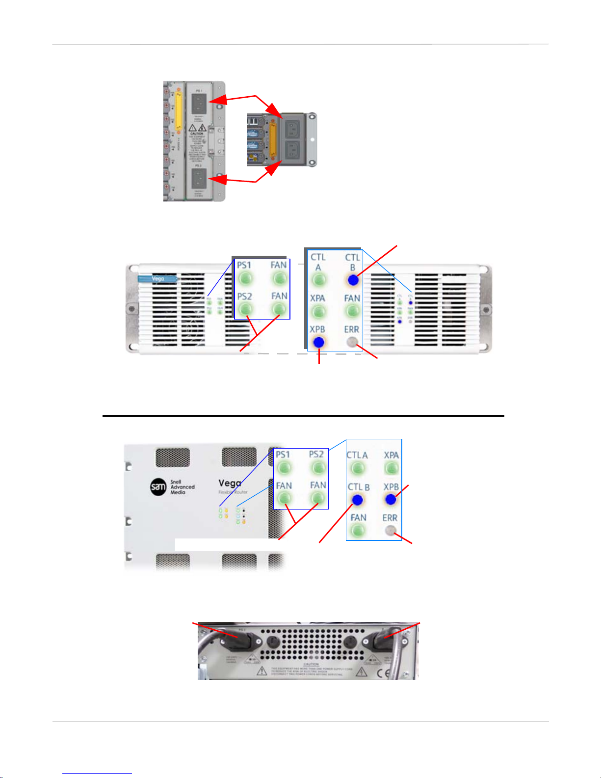
Figure 7: Vega 200 & 400 Rear IEC Power Inlets
Figure 10: Vega 700 Rear IEC Power Supply Inlets
PSU 2, rear lower inlet (for Dual PSUs only)
PSU 2
left-hand rear
inlet.
(for Dual PSUs
only)
if no PSU 2 fitted, “Off”
Figure 8: Vega 200 & 400 Front LEDs (Vega 200 shown)
“Off”
“Off”, if no second Crosspoint fitted
“Off”, if no second
Controller fitted
PSU 1
right-hand
rear inlet.
(for Single &
Dual PSUs)
“Off”
“Off”,
if no second
Controller fitted
“Off”,
if no second
Crosspoint fitted
if no PSU 2 fitted, “Off”
Figure 9: Vega 700 Front LEDs
PSU 1, rear upper inlet (for Single & Dual PSUs)
Power & Status Check
Page9 © 2016 SAM
Power & Status Check
Power
A Vega 100 Series router is supplied with either one or two Power Supply Units (PSUs).
Connect the supplied IEC mains cord to the PSU 1 rear inlet.
If a second PSU is fitted,
connect a second IEC mains cord to the PSU 2 rear inlet.
Connect the IEC cord(s) to a live mains source; the Vega will power up.
Front LED Status
Check the status of the front LED indicators after power up.
See Figures 8 (Vega 200 and 400) and Figure 9 (Vega 700).
Check the LEDs are correct for the PSU, Controller (CTL) and Crosspoint (XP) redundancy
router options fitted.
Troubleshooting
If the LED colors displayed are not as shown in the figures, please ensure that:
1. The mains supply is on and the power cord(s) are connected securely.
2. The PSU(s) and cards are all firmly seated.
If further support is required contact your local SAM representative. Contact details can be
found by visiting www.s-a-m.com/support/247-support-contact-detailsand clicking on
the Support tab. and clicking on the Support tab.
Note:
For Vega 200 & 400 - see Figure 7 and Figure 8.
For Vega 700 - see Figure 9 and Figure 10.

Vega 100 Series Routers Quick Setup Guide
Issue 4 Rev 3 Page10
CAT5 Cable Assembly
To Network Hub,
Switch or PC.
Vega 200
Vega 400
Vega 700
Figure 11: Rear Ethernet Network ports
Figure 12: Browse to the Vega home page
Enter default IP address
http://172.19.39.150/
and press Return.
Vega unit home page
loads
For information only
subnet mask:
255.255.224.0
Click Connect
Browser Login
Page11 © 2016 SAM
Browser Login
Network Connection
The Vega 100 Series router is supplied with either one or two controllers, depending on the
redundant options purchased. For the purpose of checking signal routing functionality, it is
only necessary to connect to Controller A.
1. Connect a standard CAT5 cable to port ETH 1 on the rear of the Vega router (see
Figure 11).
2. Connect the other end to your local network or PC.
3. Open a web browser on your PC.
4. Enter the default IP address of Controller A (see Figure 12).
The Vega home page displays.
5. Click on the Connect button at the bottom of the Vega home page to connect
to the Vega router.
Vega Controller Default IP Address
Controller A 172.19.39.150
Controller B 172.19.39.151
Note:
Java is required to connect to the Vega router. If Java is not installed on
your PC, click Download on the Vega home page to install Java.
Note:
To connect directly to Vega, you will need to set the IP address of your
PC manually.
Ensure the IP address you choose does not conflict with the Vega
default address.
Note:
Older PCs may require the use of a crossover CAT5 cable.
Vega 100 Series Routers Quick Setup Guide
Issue 4 Rev 3 Page12
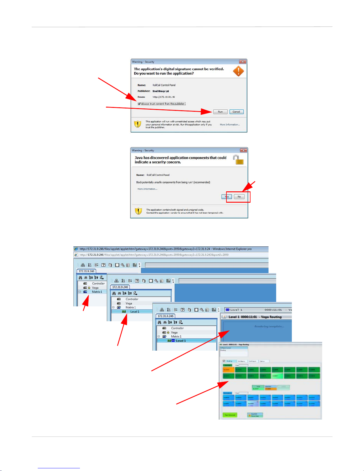
Figure 13: Digital Signature message
Figure 14: Java Security message
Check box ..
Click No
Figure 15: Network tree panel in Vega screens and displaying XY Panel.
• Click the
‘Matrix 1’
expand box
• ‘Rendering template’ displays for
a short time
before the XY Panel
.. and then
click Run
• RollCall Control Panel’s XY Panel
• Double-Click on ‘Level 1’
Page13 © 2016 SAM
Browser Login(Continued)
The browser connects to the Vega unit and a Network tree panel displays on your PC
screen. Figure 15 explains how to expand the network tree and display the XY Panel
screen.
Change the Controller IP Address details (Optional)
Required if you need to change the Vega IP address to suit your network.
• Double-click on the Controller in the Network tree panel (see Figure 16).
•ClickontheComs Setup option in the Controller window to view the current
network settings.
• Change the network settings to suit your network.
•ClickontheRestart Unit button to apply the changes.
The Vega router will restart and you will need to connect to it using the new IP address.
Note:
If an application digital signature message displays (see Figure 13)
check the Always trust content from this publisher check box and then
click Run.
Note:
If a Java security message displays (see Figure 14), click the No button.

Vega 100 Series Routers Quick Setup Guide
Issue 4 Rev 3 Page14
Figure 16: XY Panel
Enabled Sources and Destinations
Edit default names in
Edit Names tab
Corresponding Vega port number
Default names for:
source keys Srcxxxx
destination keys Destxxxx
XY Panel
The RollCall Control Panel’s XY panel (Figure 16) displays all the currently ‘enabled’ sources
and destinations. The example XY panel shown is for a router configured with 16 sources
and 16 destinations (32 ports).
Make your signal connections and use the XY panel to test your router functionality.
External Control
Page15 © 2016 SAM
External Control
Vega serial and IP ports are set by default to allow external system controllers to be directly
connected, to control the router.
Video source and destination numbers are as labelled on the router rear panels. Please
refer to the Vega User Manual for audio offsets and mapping of audio inputs and outputs.
Redundant Internal Controller (Controller B if fitted)
If the main internal controller (Controller A) fails, control is automatically transferred to the
redundant internal controller (Controller B).
Controller B is on the second ethernet port and has default IP address 172.19.39.151.
Finally
Once testing has been successfully completed, power off the Vega 100 Series router by
removing the mains leads from the live power source.
The router can now be installed where required. See the Vega 100 Series User Manual for
rack mounting details.
Updating Vega
The software and firmware of both Vega controllers can be updated remotely using the IP
network link (via the SAM RollCall control panel screen).
It is also possible to update the firmware of the input/output cards and the crosspoint
cards.
Please refer to the Vega 100 Series user manual for the recommended update procedure.
Vega Control Ports Configured Protocol Comment
Serial ports 1-4 SW-P-02 in
IP interface ports SW-P-02 in (IP port 2008)
Note:
A RollCall Control Panel will always connect to the active controller. By
default this is Controller A with two functioning internal controllers.

Notes:
Company policy is one of
continuous product improvement.
Specifications are subject to
change without notice.
www.s-a-m.com
SAM
Turnpike Road, Newbury,
Berkshire, RG14 2NX, UK.
Vega 100 Series Routers Quick Setup Guide Issue 4 Rev 3
RMY3 VEGA100QSG
www.s-a-m.com
© 2016 SAM
All rights reserved.
Other manuals for Vega 200
1
This manual suits for next models
2
Table of contents
Other Snell Advanced Media Network Router manuals


