Snell & Wilcox IQBRT8 User manual

IQBRT8 SECTION 41b
IQBRT8OPS 020403 Version 1 Issue 7 41b.1
IQBRT8 Digital Audio Router
Module Description
The IQBRT is a range of professional quality
Synchronous Digital Audio Routers, and are
capable of routing up to 8x8 AES/EBU pairs. The
IQBRT can accept PCM digital audio at sampling
rates of 16 kHz to 96 kHz and will automatically
detect the recognised standards of 32, 44.1 and 48
kHz. The IQBRT accepts both AES/EBU and
SPDIF (-B versions only) inputs, and outputs
professional AES/EBU digital audio. The Router
also has an AES/EBU monitoring output for
previewing input material. The IQBRT sample rate
converts all PCM audio inputs to 48 kHz with no
loss of audio quality. The outputs are then
synchronised to either 525 or 625 line video, or a
48 kHz AES Reference, and are frame aligned in
accordance to the AES11 specification. In the
absence of a reference the inputs can be re-
sampled to an internal 48 kHz reference of 10ppm
or Input 1. The IQBRT also accepts 48 kHz non-
PCM audio bitstreams but must be synchronous to
the IQBRT synchronising source.
All switching of PCM audio is done via v-fading, to
give seamless glitch-free routing. Non-PCM audio
bitstreams are switched (with no data processing)
on data packet boundaries.
The IQBRT Programme level on any of the inputs
(AES pair) can be adjusted from + 6dB to – 18dB
in 0.1dB steps, each input can also be polarity
inverted or muted. A built-in test tone generator is
also included and can be assigned to any number
of outputs for ease of system set-up.
The IQBRT’s digital audio interface is available in
either transformer coupled balanced (-D) or
unbalanced (-B) type.
Full remote control via RollCallTM is included as
standard, which will enables complete control over
the IQBRT.
REAR PANEL VIEWS
2
IQBRT8-3-B
AES AUDIO OUTPUTS
2
1
5
4
MON
AES
/
SPDIF INPUTS
REF
3
13
2
46
2
8
7
65
78
IQBRT8-3-B IQBRT8 8x8 Digital Audio Router Unbalanced I/O
C

IQBRT8 SECTION 41b
IQBRT8OPS 020403 Version 1 Issue 7 41b.2
IQBRT8-2-D
REFAES AUDIO INPUTS
AES AUDIO OUTPUTS AES REF IN/MON OUT
IQBRT8-2-D IQBRT8 8x8 Digital Audio Router Balanced I/O
2
IQBRT6-2-B
AES OUTPUTS
2
1
4
3MON
AES
/
SPDIF INPUTS
REF
1
24
3
56
IQBRT6-2-B IQBRT6 6x4 Digital Audio Router Unbalanced I/O
IQBRT6-2A-B IQBRT6 6 x 4 Digital Audio Router Unbalanced I/O

IQBRT8 SECTION 41b
IQBRT8OPS 020403 Version 1 Issue 7 41b.3
Versions of the module cards available are:
IQBRT8-2-D IQBRT8 8 x 8 Digital Audio Router Balanced Double width module
IQBRT8-3-B IQBRT8 8 x 8 Digital Audio Router Unbalanced Triple width module
IQBRT6-2-B IQBRT6 6 x 4 Digital Audio Router Unbalanced Double width module
IQBRT6-2A-B IQBRT6 6 x 4 Digital Audio Router Unbalanced Double width module
Note that there are two styles of rear panels available. They are not interchangeable between the two
styles of enclosures. However, the cards may be fitted into any style of enclosure.
‘A’ Style Enclosure
Rear panels with the suffix A may only be fitted
into the ‘A’ style enclosure shown below.
IQ
(Enclosure order codes IQH3A-E-O, IQH3A-E-P,
IQH3A-N-O, IQH3A-N-P)
‘O’ Style Enclosures
Rear panels without the suffix A may only be fitted
into the ‘O’ style enclosures shown below.
setup
lock save
rec al l
modules help
adjust
scro ll
power previous
return
home
cont rol
information
display
sele ct
power
(Enclosure order codes IQH1S-RC-O, IQH1S-RC-
AP, IQH1U-RC-O, IQH1U-RC-AP, Kudos Plus
Products)
power
OPEN
(Enclosure order codes IQH3N-O, IQH3N-P)

IQBRT8 SECTION 41b
IQBRT8OPS 020403 Version 1 Issue 7 41b.4
BLOCK DIAGRAM
Data packet
boundary
& Cross -
fader
switcher
Ch 1
Ch 2
CS Editor
&
Encoder
Tx AES Out 1
Ch 3
Ch 4
CS E d ito r
&
Encoder
Tx AES O ut 2
Ch 13
Ch 14
CS Editor
&
Encoder
Tx AES Out 7
Ch 15
Ch 16
CS Editor
&
Encoder
Tx AES Out 8
Test Tone
Generator
SPG
Rx
Sync
Separator
48 kHz
AES Ref
Video Ref
uProc
RollCall
Rx Re-sampler
Selector
Re-framer
AES In 1
Rx Re-sampler
Selector
Re-framer
AES In 2
Rx Re-sampler
Selector
Re-framer
AES In 7
Rx Re-sampler
Selector
Re-framer
AES In 8
To uProc
To uProc
To uProc
To uProc
To Receivers
17
Tx
Encoder AES MON
Data packet
boundary
& Cross -
fader
switcher
Data packet
boundary
& Cross -
fad er
switcher
Data packet
boundary
& Cross -
fad er
switcher
Proc-Amp
Proc-Amp
Proc-Amp
Proc-Amp
Features
•Up to 8x8 AES/EBU Router for PCM and non-PCM audio , plus an AES Preview output
•24 bit sampling rate converters on all inputs required to synchronize asynchronous digital audio to either
525 or 625 video, an AES Reference or freerun.
•Automatic 32, 44.1 and 48 kHz detection
•Professional AES/EBU 48 kHz output
•Unbalanced version is Dolby E compatible
•Glitch-free switching of digital audio.
•Input error detection indicator and reporting
•Independent phase reversal on any input subframe
•Support for non-PCM data, with automatic detection
•Data packet boundary switching for non-PCM audio bitstreams (no audio processing performed)
•Framing error correction of up to one sample
•Programme level adjust on each input channel from + 6 dB to –18 dB in 0.1 dB steps
•Built-in Test tone generator to ensure ease of system set-up
•Channel status monitoring of AES receivers and transmitters
•Channel status editor
•Remote Peak Programme Meter with adjustable 0 dB reference
•Eight memory locations for storage and recall of selectable parameters
•RollCall remote control and reporting/logging

IQBRT8 SECTION 41b
IQBRT8OPS 020403 Version 1 Issue 7 41b.5
TECHNICAL PROFILE
Features
Signal Inputs
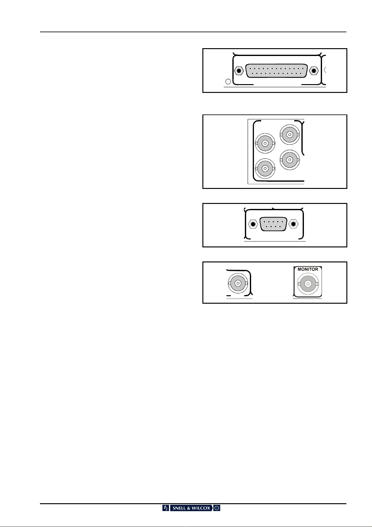
Digital Audio Input (Balanced –D versions)
8 Channel Pairs AES/EBU
via 25 way D Connector
Digital Audio Input (Unbalanced –B versions)
8/6 Channel Pairs AES/EBU
via BNC Connectors
AES Reference Input (Balanced –D versions)
Sample Frequency 48 kHz via 9
way D Connector or via BNC
connector
Reference Input (Balanced –D versions)
525/625 line Black Burst via BNC
connector
Reference Input (Unbalanced –B versions)
525/625 line Black Burst, or
unbalanced AES/EBU sample
frequency 48 kHz via BNC
connector
Signal Outputs
Digital Audio (Balanced –D versions)
8 channel pairs AES/EBU
via 25 way D Connector
Digital Audio (Unbalanced –B versions)
8/4 channel pairs AES/EBU
via BNC Connectors
Digital Audio Monitor (Balanced –D versions)
1 channel pair AES/EBU
via 9 way D Connector
Digital Audio Monitor (Unbalanced –B versions)
1 channel pair AES/EBU
via BNC Connector
Card Edge Controls (also available via RollCall)
Router Mode only, Configure output channels
Independently configure the 8
outputs to any of the 8 inputs
Take Button ....................... Initiates routing
Indicators
AES Input error .................. Illuminates when there is an error
on the AES inputs
Sync Loss .......................... Illuminates when locking source is
lost
Take LED........................... Flashes when routing assignment
has changed and requires initiating
via take button
Power OK .......................... +5 V, -5 V
Functions Available via RollCall™ Only
Input Sample rate detection Automatic 32, 44.1, 48 kHz
detection
Input programme level adjust
Adjusts input programme level for
each input channel from
+ 6 dB to -18 dB in 0.1 dB steps
Test tone insertion ............. Insert test tone or silence into any
output sub-frame
Test tone frequency ........... Select test tone frequency from
250 Hz to 16 kHz in 250 Hz steps
Lock select......................... Selects synchronizing source, from
either:- Video, AES Reference,
Input 1 or freerun
AES Input status monitor ... Displays AES format and status
Channel Status Monitor...... Displays input or output channel
status for any subframe
Channel Status Editor ........ Enables user to edit Channel
status information
Peak Programme Meter for any input
Scale of 0 - 7, 4 dB steps,
adjustable 0 dBu reference (‘4’) –
10 dBFS to
-24 dBFS
Phase reversal ................... Independent phase reversal for any
input subframe
Eight memory stores .......... Storage and recall of selected
parameters

IQBRT8 SECTION 41b
IQBRT8OPS 020403 Version 1 Issue 7 41b.6
Specifications
Input Impedance ................ Balanced 110 Ohm
Unbalanced 75 Ohm
Cable Length ..................... Balanced, > 150 m of AES3 Cable
Unbalanced, up to 500 m of RG59
or Equivalent
Input Sample Frequency .... 16 – 96 kHz, Input ‘1’ 48 kHz ±2 Hz
if selected as the locking reference
Output Impedance ............. Balanced 110 Ohm
Unbalanced 75 Ohm
Output Signal level............. Balanced 3 V pk to pk typical
Unbalanced 1 V pk to pk typical
Output Return Loss (-B)..... 33 dB at 6 MHz
Output Sampling ................ 48 kHz frame locked to 48 kHz
AES/EBU reference, 48 kHz frame
locked to PAL video reference,48
kHz frame locked to every 5th
frame of an NTSC video reference
(Conforms to AES11 – 1997 spec)
Free run stability Grade 2... ±10 ppm
Digital Reference Input Pull-In Range
±2 Hz
Distortion (THD + Noise) 24 bits
–117 dB, 1 kHz@ -1 dBFS, SRC
I/O ratio < 0.33 to 1.7 –104 dB,
1 kHz@
-1 dBFS, SRC I/O ratio < 0.33 to 3
Dynamic Range ................. 120 dB
Channel Status delay ......... 4 ms @ 48 KHz FSI/FSO
User data delay.................. 4 ms @ 48 KHz FSI/FSO
Fader time.......................... 12.8 ms
Fader cut-off level .............. - 60 dBFS
Jitter................................... < 0.005 UI p-p
Audio processing delay (48 kHz I/O sample frequency)
1.9 ms max. with sampling rate
conversion TBD µs without
sampling rate conversion
Power Consumption
Module Power Consumption
IQBRT8 5.7W max (balanced
versions)
IQBRT8 7W max (unbalanced
versions)
IQBRT6 5.4W max (unbalanced
versions)
Performance Information
Standards .......................... EN55103-1:1996 (Environment E2)
EN55103-2:1996 (Environment E2)
FCC Part 15, Class A (Verification)
Inrush Current ................... Please refer to IQ Modular Box
manual
Performance Degradation: None

IQBRT8 SECTION 41b
IQBRT8OPS 020403 Version 1 Issue 7 41b.7
INPUTS AND OUTPUTS
AES Audio Inputs (-D version)
All AES Audio input connections are made via this
25 way female D-type connector.
For connection data consult the tables on page 5.
AES Audio Inputs (-B versions)
All AES Audio input connections are made via BNC
connectors.
AES Reference Input (-D version)
A 48 kHz AES reference signal may be connected
to this 9 way D connector. When this input is
selected the outputs will be locked to this signal.
Reference Input (–D version)
This is for a video reference only. A black burst
signal (525 or 625 line standard) may be
connected to this BNC connector.
Reference Input (–B versions)
This is for a video reference and or an AES
reference signal.
The video signal may be a black burst or a
composite signal (525 or 625 line standard).
The AES reference should be a 48 kHz signal.
As supplied this input will terminate the signal in
75 Ohms. To change this to a high impedance
input remove the link as shown opposite.
IQBR
T
AES AUDIO INPUTS
2
MON
AES
/
SPDIF INPUTS
REF
1
24
3
56
AES REF IN/MON OUT
REF
REF
-D version -B versions

IQBRT8 SECTION 41b
IQBRT8OPS 020403 Version 1 Issue 7 41b.8
AES Audio Outputs (-D versions)
All AES Audio output connections are made via
this 25 way female D-type connector.
For connection data consult the tables on page 5.
AES Audio Outputs (-B versions)
All AES Audio output connections are made via
BNC connectors.
Monitor Output (-D version)
A channel status monitoring display output is also
available from this 9 way D connector.
For connection data consult the tables on page 7.
Monitor Output (-B versions)
A monitoring output is also available from this BNC
connector.
RT8-2-D
AES AUDIO OUTPUTS
IQBRT6-2-B
AES OUTPUTS
2
1
4
3
AES REF IN/MON OUT
MON

IQBRT8 SECTION 41b
IQBRT8OPS 020403 Version 1 Issue 7 41b.9
9 WAY D CONNECTOR IQBRT8-2-D
9 Way D Connector
Pin Number FUNCTION Standard Pin
Assignment
1 CHASSIS
6 AES REF IN 1 Ground GND1
2 AES REF IN 1 + 1+
7 AES REF IN 1 - 1-
3 AES MON OUT + 2+
8 AES MON OUT - 2-
4 AES MON OUT Ground GND2
9 GND3
53+
25 WAY D CONNECTION DATA IQBRT8-2-D
25 Way D Connector
Pin Number
INPUTS
IQBRT8-2-D
OUTPUTS
IQBRT8-2-D
Standard Pin
Assignment
1 CHASSIS
14 AES IN 1 Ground AES OUT 1 Ground GND1
2 AES IN 1 + AES OUT 1 + 1+
15 AES IN 1 - AES OUT 1 - 1-
3 AES IN 2 + AES OUT 2 + 2+
16 AES IN 2 - AES OUT 2 - 2-
4 AES IN 2 Ground AES OUT 2 Ground GND2
17 AES IN 3 Ground AES OUT 3 Ground GND3
5 AES IN 3 + AES OUT 3 + 3+
18 AES IN 3 - AES OUT 3 - 3-
6 AES IN 4 + AES OUT 4 + 4+
19 AES IN 4 - AES OUT 4 - 4-
7 AES IN 4 Ground AES OUT 4 Ground GND4
20 AES IN 5 Ground AES OUT 5 Ground GND5
8 AES IN 5 + AES OUT 5 + 5+
21 AES IN 5 - AES OUT 5 - 5-
9 AES IN 6 + AES OUT 6 + 6+
22 AES IN 6 - AES OUT 6 - 6-
10 AES IN 6 Ground AES OUT 6 Ground GND6
23 AES IN 7 Ground AES OUT 7 Ground GND7
11 AES IN 7 + AES OUT 7 + 7+
24 AES IN 7 - AES OUT 7 - 7-
12 AES IN 8 + AES OUT 8 + 8+
25 AES IN 8 - AES OUT 8 - 8-
13 AES IN Ground AES OUT Ground GND8

IQBRT8 SECTION 41b
IQBRT8OPS 020403 Version 1 Issue 7 41b.10
Example of Connection Details to XLR Connectors (-D versions)
25 way Connection Data
IQBRT8-2-D 8 x 8
9 way Connection Data
IQBRT8-2-D 8 x 8
AES In/Out 2
AES In/Out 4
AES In/Out 6
AES In/Out 8
AES In/Out 1
AES In/Out 3
AES In/Out 5
AES In/Out 7
AES Monitor Output
AES Reference Input

IQBRT8 SECTION 41b
IQBRT8OPS 020403 Version 1 Issue 7 41b.11
CARD EDGE CONTROLS
LED INDICATORS
D1 and D2
When illuminated, D1 and D2 indicate that the +5V
and the -5V power supplies are present.
D3
When illuminated, D3 will indicate that the selected
locking source has been lost.
AES Input Status
These LED’s indicate the status of the inputs.
The LED will flash if there is no AES signal at that
input. The LED will be OFF if the input is OK.
Take
If a routing assignment has been changed this LED
will flash slowly for approximately 20 seconds,
flash quickly for approximately 3 seconds and then
stop.
The pushbutton should be pressed before the
flashing stops to initiate the change.

IQBRT8 SECTION 41b
IQBRT8OPS 020403 Version 1 Issue 7 41b.12
SW1
This switch selects the source of the input signal
as shown in the table below:
Position Input Source
11
22
33
44
55
66
77
88
9 Silence
0 Do not use this position
Note that only positions 1 to 6 and 9 are used on
the IQBRT6-2.
SW2
This switch selects the output destination as shown
in the table below:
Note that only positions 1 to 4 are used on the
IQBRT6-2.
Position Output
11
22
33
44
55
66
77
88
9 Do not use this position
0 Do not use this position
Note that after each change of the Input/Output
routing the TAKE pushbutton should be pressed to
initiate the change.

IQBRT8 SECTION 41b
IQBRT8OPS 020403 Version 1 Issue 7 41b.13

IQBRT8 SECTION 41b
IQBRT8OPS 020403 Version 1 Issue 7 41b.14
OPERATION FROM AN ACTIVE CONTROL PANEL
The card may be operated with an active control panel via the RollCall™ network.
The menus available for this card are shown on page opposite and will appear in the Control display window.
Operational details for the remote control panel will be found in SECTION 1 of the Modular System Operator's
Manual.
MENU DETAILS
(see IQBRT8 Menu System Opposite)
Note that menus for the IQBRT6 are the same the
IQBRT8 except for the number of inputs and
outputs.
MAIN MENU
The main, or top level menu allows various sub-
menus to be selected by pressing the button
adjacent to the required text line.
Note that where a menu item is followed by three
dots (...) this indicates that a further sub-menu may
be selected.
Whenever a menu item is selected the parameters
of that selection will be displayed in the Information
window of the front panel. Where the selection is
purely a mode selection and does not enable a
sub-menu, the text will become reversed (white-on-
black) indicating that the mode is active. If the
mode is not available for selection the text will
remain normal.
◀Crosspoint…
This function allows the input/output routing to be
set up and operated.
Crosspoint
Router...
Ta ke!
Protect...
Monitor...
Cancel!
Enable_Take
◀
◀◀
◀Router…
The Router allows the assignment of any of the
outputs (destinations) to any of the inputs
(sources) or to silence.
◀Dest_1 to 7 Dest_2 to 8 ▶
When a destination is selected this will reveal a
menu that allows any of the sources (or silence) to
be routed to this destination.
◀
◀◀
◀Take!
Selecting this function will enable the changes
made to the router assignments.
Cancel!… ▶
Selecting this function will cancel any changes
made to the router assignments if the
Enable_Take function has been selected.

IQBRT8 SECTION 41b
IQBRT8OPS 020403 Version 1 Issue 7 41b.15
◀
◀◀
◀Enable_Take
When selected (text highlighted) this function will
allow the Take function to be operated.
When not selected (text normal) any changes
made to the routing assignments will occur
immediately.
Preset is to selected (text highlighted).
◀
◀◀
◀Protect
This function allows the selected
source/destination route to be locked. The route
cannot then be disturbed by other controls.
Protect
Dest_1
Dest_3
Dest_5
Dest_7
Dest_2
Dest_4
Dest_6
Dest_8
Monitor… ▶
This function allows an input source (before any
processing) to be selected and monitored by an
AES monitoring device connected to the
monitoring output on the rear panel.

IQBRT8 SECTION 41b
IQBRT8OPS 020403 Version 1 Issue 7 41b.16
◀Memories…
This function reveals a sub-menu that allows
control of the memory functions.
◀
◀◀
◀Recall…
This function reveals a sub-menu that allows 8
different settings of all items to be recalled from the
8 memory locations as saved in the Save function.
◀
◀◀
◀Save…
This function reveals a sub-menu that allows the
settings of all items to be saved. Up to 8 different
set-ups may be saved in the 8 memory locations.
They can all be renamed using the Names menu
Preset… ▶
This selection allows individual (select the location
memory number), or all, (select
Preset_All_Memories), memory locations to be
preset to their default (factory) settings.
Names… ▶
This selection allows the naming of memory 1 to 8
locations.
To name a memory location select:
Names… ▶to reveal the sub-menu.
Select the memory location to be renamed e.g.
◀Memory_1
To compile/edit the text the right ▶and left ◀
buttons adjacent to the upper text line in the menu
should be used to select the character position in
the text and the spinwheel used to select the
character.
The ◀Clear function blanks out the selected
character.
The ◀Preset function loads the default text, for
example, Memory_1.
O.K. ▶saves the caption text and returns to the
main menu.

IQBRT8 SECTION 41b
IQBRT8OPS 020403 Version 1 Issue 7 41b.17
◀Name_Assoc…
This selection allows the naming of the input
sources and the output destinations.
To name an association, select either
◀
◀◀
◀Source… or ◀
◀◀
◀Dest… to reveal the appropriate
sub-menu.
Select the Source/Destination to be renamed from
the list.
e.g.◀Source_1
This will reveal the renaming screen.
To compile/edit the text the right ▶and left ◀
buttons adjacent to the upper text line in the menu
should be used to select the character position in
the text and the spinwheel used to select the
character.
The ◀Clear function blanks out the selected
character.
The ◀Preset function loads the default text, for
example, Memory_1.
O.K. ▶saves the text and returns to the main
menu.
Note that the new name will replace the old name
in all relevant menus.
Display… ▶
▶▶
▶
This menu allows information about the
input/output signals and channel status to be
displayed in the information LCD window.
◀
◀◀
◀Prev Next ▶
▶▶
▶
The previous and next functions allow the previous
Input/Output or the next Input/Output to be
selected for viewing in the information display.
◀
◀◀
◀Subframe 1 Subframe 2 ▶
▶▶
▶
These functions allow information about the two
subframes to be selected and viewed in the
display. (Channel Status only)
◀
◀◀
◀Inputs…
This item may be used to select the inputs for
interrogation. Data will be shown in the Information
LCD.
The following data may be displayed about the
currently selected item (selected via the Display
menu above). The ◀
◀◀
◀Prev and Next ▶
▶▶
▶functions
should be used to select and display other items.
◀Input_Status
This will display information about the input and the
reference source.
Fsi indicates the sample rate.
The line standard of the video reference is shown
and may be 625 or 525 or LOST.
Note that if the source or a reference signal has
been lost OK will be replaced by **

IQBRT8 SECTION 41b
IQBRT8OPS 020403 Version 1 Issue 7 41b.18
◀Input_Gains
This will display the gain settings of the selected
input and also the sampling rate.
The display will also indicate whether or not the
input has been inverted by inserting a suffix of INV
or if the input has been muted by inserting
MUTED. If the input characteristics have not been
changed PASS will be shown.
◀Input_PPMs
This selection will reveal a bargraph display
showing the peak level of the both input subframes
of the selected input.
The scale is divided into 8 equal divisions, each
representing a 4 dB level increment.
The 0 dB point is defined as 4 and maybe set to
between –12 dBFS and –24 dBFS using the PPM
Scaling item in the Setup menu.
This metering function follows standard Peak
Programme characteristics.
◀Input_CS_Data
Selecting this item will display information about
the Source channel status (for the selected
subframe), examples of which are shown below:
◀
◀◀
◀Up Down ▶
▶▶
▶
These buttons should be used to scroll through the
items in the above menu.
Outputs…▶
▶▶
▶
This menu allows information about the status of
the output and will be displayed in the information
LCD window.
Selections available are:
◀Output_Status
The first line shows which input (Source) is routed
to which selected output (Destination).
The second line provides data about the Source
signal and its’ sample rate.
The third line gives data about the Locking signal
as selected via the ◀
◀◀
◀Lock function.
This may be either:
Video Reference
Input 1
AES Reference
Internal

IQBRT8 SECTION 41b
IQBRT8OPS 020403 Version 1 Issue 7 41b.19
◀Output_CS_Data
Selecting this item will display information about
the output channel status (for the selected
subframe), examples of which are shown below:
◀
◀◀
◀Up Down ▶
▶▶
▶
These buttons should be used to scroll through the
items in the above menu.
ProcAmp… ▶
▶▶
▶
◀
◀◀
◀Gain…
This function allows the inputs to be muted and
INPUT gain to be adjusted.
Note if a non-audio input source (AC3 or other
compressed audio data) has been detected the
Procamp and other processing settings (except
routing functions) will be disabled and the signal
will pass through unprocessed.
Also under these conditions the "Fsi: " item in the
information display will be replaced with
"NON-PCM", as it is assumed that the non-audio
data-sampling rate is 48 KHz.
◀Input_1 to 7 Input_2 to 8… ▶
Selecting an input will reveal a menu that allows
the gain of that input to be adjusted and either of
the subframes to be muted.
◀Input_1 to 8 Gain…
The gain function reveals a numerical display
showing the gain in dB that is adjustable using the
spinwheel.
The range of adjustment is from –18 dB to +6 dB
in steps of 0.1 dB. Preset is to 0. 0dB.
◀Mute_Input_1 to 8 SF1
Selecting this item will mute Subframe 1 of the
selected Input.
◀Mute_Input_1 to 8 SF2
Selecting this item will mute Subframe 2 of the
selected Input.
Polarity… ▶
▶▶
▶
This allows the inversion of any of the input
subframes (phase swapping of 1800).
◀Input_1 to 7… Input_2 to 8… ▶
The input should be selected from the Polarity
menu and the inverting action selected from the
following menu:
Note that when the text is highlighted polarity is
inverted.

IQBRT8 SECTION 41b
IQBRT8OPS 020403 Version 1 Issue 7 41b.20
Setup… ▶
▶▶
▶
This selection reveals a sub-menu that allows
various functions to be set.
◀
◀◀
◀Lock
This selection reveals a sub-menu that allows the
option to reframe the input(s) to different reference
signals.
If no locking inputs are detected then the unit will
revert to the internal mode (free-running at 48 kHz)
The locking information will be displayed when the
Inputs display is selected.
Selections available are:
◀Video
Unit will lock to the video input Reference signal
◀AES_Reference
Unit will lock to the AES Reference.
Note that when locking to the AES reference the
pull in range is ±2 Hz, if the reference is 48 KHz
but out of this range (PLL unable to maintain lock)
the information display will indicate "ERR" instead
of "OK" and Fsi will indicate the reference input
sampling rate to the nearest 1 kHz.
◀Input_1
Unit will lock to the signal at Input 1
◀Internal
The unit will free-run at a sample rate of 48 kHz.
Table of contents
Other Snell & Wilcox Switch manuals