Icom IC-M503 User manual

INSTRUCTION MANUAL
iM503
VHF MARINE TRANSCEIVER
01 IC-M503-(1).qxd 01.12.17 5:00 PM Page a (1,1)

If your vessel requires assistance, contact other vessels and
the Coast Guard by sending a distress call on Channel 16.
Or, transmit your distress call using digital selective calling on
Channel 70 (the optional DS-100 (#02) must be installed).
USING DIGITAL SELECTIVE CALLING (Ch 70)
(DS-100 (#02) DSC CONTROLLER is required)
DISTRESS CALL PROCEDURE
1. Push and hold [DISTRESS] on the DS-100
for 5 sec. until you hear 5 short beeps
change to one long beep.
2. Wait for an acknowledgment from a coast
station.
• Channel 16 is automatically selected.
3. Push and hold [PTT], then transmit the
appropriate information as at left.
USING CHANNEL 16
DISTRESS CALL PROCEDURE
1. “MAYDAY MAYDAY MAYDAY.”
2. “THIS IS ...............” (name of vessel)
3. Your call sign or other indication of the
vessel (AND 9-digit DSC ID if you have one).
4. “LOCATED AT ...............” (your position)
5. The nature of the distress and assistance
required.
6. Any other information which might facilitate
the rescue.
IN CASE OF EMERGENCY
i
Versions of the IC-M503 which display the “CE” symbol on
the serial number seal, comply with the essential requirements of the
European Radio and Telecommunication Terminal Directive
1999/5/EC.
This warning symbol indicates that this equipment operates in
non-harmonised frequency bands and/or may be subject to licensing
conditions in the country of use. Be sure to check that you have the
correct version of this radio or the correct programming of this radio,
to comply with national licensing requirements.
01 IC-M503-(1).qxd 01.12.17 5:00 PM Page b (1,1)

ii
TABLE OF CONTENTS
IN CASE OF EMERGENCY ........................i
TABLE OF CONTENTS ..............................ii
IMPORTANT ..............................................iii
CAUTIONS.................................................iii
1 OPERATING RULES .......................... 1
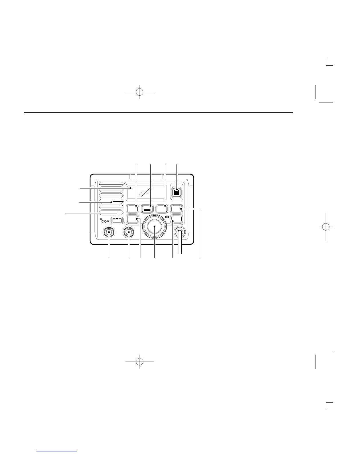
2 PANEL DESCRIPTION .................. 2 – 5
■ Panel description ............................. 2
■ Function display ............................... 4
■ Microphone ...................................... 5
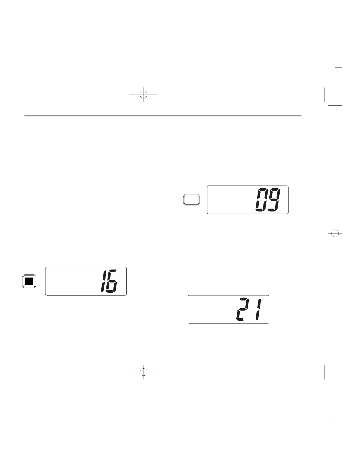
3 BASIC OPERATION .................... 6 – 10
■ Channel selection ............................ 6
■ Receiving and transmitting .............. 8
■ Call channel programming ............... 9
■ Channel names ................................ 9
■
Optional voice scrambler operation
.. 10
4 DUALWATCH/TRI-WATCH ............... 11
■ Description ..................................... 11
■ Operation ....................................... 11
5 SCAN OPERATIONS ................. 12 – 13
■ Scan types ..................................... 12
■ Setting tag channels ...................... 13
■ Starting a scan ............................... 13
6 SET MODE ................................. 14 – 16
■ Set mode programming ................. 14
■ Set mode items .............................. 15
7 INTERCOM OPERATION ................. 17
■ Intercom operation ......................... 17
8 CONNECTIONS AND
MAINTENANCE ......................... 18 – 24
■ Unpacking ...................................... 18
■ Antenna ......................................... 18
■ Fuse replacement .......................... 18
■ Cleaning ......................................... 18
■ Connections ................................... 19
■ Microphone hanger ........................ 20
■ Mounting the transceiver ............... 21
■ Optional unit installation ................. 23
■ Dimensions ..................................... 24
9 TROUBLESHOOTING ...................... 25
10 CHANNEL LIST ................................ 26
11 SPECIFICATIONS AND OPTIONS ... 27
■ Specifications ................................. 27
■ Options .......................................... 27
12 HM-134 REMOTE-CONTROL
MICROPHONE ........................... 28-38
■ Panel description ........................... 28
■ Function display ............................. 30
■ Channel selection .......................... 32
■ Receiving and transmitting ............ 33
■ Lock functions ................................ 34
■ Display backlighting ....................... 34
■ Monitor function ............................. 34
■ Call channel programming ............. 35
■ Optional voice scrambler
operation......................................... 35
■ Starting a scan ............................... 36
■ Setting tag channels ...................... 36
■ Dualwatch/Tri-watch operation ...... 36
■ Set mode programming ................. 37
■ Intercom operation ......................... 38
■ Channel names .............................. 38
13 HM-134 CONNECTIONS AND
INSTALLATION ........................... 39-41
■ HM-134 supplied accessories .........39
■ Installation .......................................39
MB-75 TEMPLATE
INSTALLATION NOTES
01 IC-M503-(1).qxd 01.12.17 5:00 PM Page c (1,1)

iii
READ ALL INSTRUCTIONS carefully and completely
before using the transceiver.
SAVE THIS INSTRUCTION MANUAL —This in-
struction manual contains important operating instructions for
the IC-M503.
RWARNING! NEVER connect the transceiver to an AC
outlet. This may pose a fire hazard or result in an electric
shock.
NEVER connect the transceiver to a power source of more
than 15.6 V DC or using reverse polarity. This will ruin the
transceiver.
NEVER cut the DC power cable between the DC plug and
fuse holder. If an incorrect connection is made after cutting,
the transceiver may be damaged.
NEVER place the transceiver where normal operation of the
vessel may be hindered or where it could cause bodily injury.
KEEP the transceiver at least 1 m away from the ship’s nav-
igation compass.
DO NOT use or place the transceiver in areas with temper-
atures below –20°C or above +60°C or, in areas subject to di-
rect sunlight, such as the cockpit.
AVOID the use of chemical agents such as benzine or al-
cohol when cleaning, as they may damage the transceiver
surfaces.
BE CAREFUL! The transceiver rear panel will become
hot when operating continuously for long periods.
BE CAREFUL! The optional HM-134 remote-control mi-
crophone’s rear panel will become hot when monitoring con-
tinuously for long periods.
Place the transceiver in a secure place to avoid inadvertent
use by children.
After exposure to salt water, clean the transceiver thoroughly
with fresh water to avoid corrosion.
CAUTIONS
IMPORTANT
01 IC-M503-(1).qxd 01.12.17 5:00 PM Page d (1,1)

1
1
OPERATING RULES
ïïPRIORITIES
•Read all rules and regulations pertaining to priorities and
keep an up-to-date copy handy. Safety and distress calls
take priority over all others.
•You must monitor Channel 16 when you are not operating
on another channel.
•False or fraudulent distress signals are prohibited and pun-
ishable by law.
ïïPRIVACY
•Information overheard but not intended for you cannot law-
fully be used in any way.
• Indecent or profane language is prohibited.
ïïRADIO LICENSES
(1) SHIP STATION LICENSE
You must have a current radio station license before using the
transceiver. It is unlawful to operate a ship station which is not
licensed.
Inquire through your dealer or the appropriate government
agency for a Ship-Radiotelephone license application. This
government-issued license states the call sign which is your
ship’s identification for radio purposes.
(2) OPERATOR’S LICENSE
A Restricted Radiotelephone Operator Permit is the license
most often held by small ship radio operators when a radio
is not required for safety purposes.
The Restricted Radiotelephone Operator Permit must be
posted or kept with the operator. Only a licensed radio opera-
tor may operate a transceiver.
However, non-licensed individuals may talk over a transceiver
if a licensed operator starts, supervises, ends the call and
makes the necessary log entries.
Keep a copy of the current government rules and regulations
handy.
01 IC-M503-(1).qxd 01.12.17 5:00 PM Page 1 (1,1)

PANEL DESCRIPTION
2
2
■Panel description
CALLDUAL SCAN
WATER RESISTANT
TAG DIAL
DIMMER
HI/LO
POWER
VOL
iM503
VHF MARINE
SQL
16
Speaker
Function
display
q
werty u
io!0!1
qPOWER SWITCH [POWER]
Push to toggle the transceiver power ON and OFF.
wVOLUME CONTROL [VOL]
Adjusts the audio level. (p. 8)
eSQUELCH CONTROL [SQL]
Sets the squelch threshold level. (p. 8)
rTRANSMIT POWER SWITCH [HI/LO]
➥Push to Toggle high and low power . (p. 8)
•Some channels are set to low power only.
➥While pushing and holding this switch, other switches
perform secondary functions.
01 IC-M503-(1).qxd 01.12.17 5:00 PM Page 2 (1,1)

tCHANNEL SELECTOR [CHANNEL]
Rotate [CHANNEL] to select the operating channels, set
mode contents, etc. (p. 8)
yDIMMER SWITCH [DIMMER]
➥Push to select one of 8 backlighting (LCD and switches)
levels.
➥Push and hold for 1 sec. to turn the intercom mode ON.
uCALL CHANNEL SWITCH [CALL]
➥Push to select the call channel. (p. 6)
➥Push and hold for 3 sec. to enter call channel program-
ming condition. (p. 9)
➥While pushing and holding [HI/LO], enters memory
name programming condition. (p. 9)
iCHANNEL 16 SWITCH [16]
➥Push to select Channel 16. (p. 6)
➥While turning power ON, push to enter initial set mode.
(p. 14)
oDIAL SWITCH [DIAL]
➥Push to exit from Channel 16 or call channel.
(p. 6)
➥While pushing and holding [HI/LO], push to select chan-
nel group. (pgs. 6, 7)
•The “EUR”version has International channels only and this
function is not available.
!0 SCAN SWITCH [SCAN/TAG] (p. 13)
➥When tag channels are programmed, starts and stops
normal or priority scan.
➥Push and hold [SCAN/TAG] for 1 sec. to set the dis-
played channel as a tag (scanned) channel.
➥While pushing and holding [HI/LO], push and hold for 3
sec. to clear all tag channels.
!1 DUALWATCH/TRI-WATCH SWITCH [DUAL] (p. 11)
➥Push to start dualwatch or tri-watch.
➥When dualwatch/tri-watch is activated, push to stop
them.
PANEL DESCRIPTION
3
2
01 IC-M503-(1).qxd 01.12.17 5:00 PM Page 3 (1,1)

■Function display
qBUSY/TRANSMIT INDICATOR (p. 8)
➥“BUSY”appears when receiving a signal or when the
squelch opens.
➥“TX”appears while transmitting.
wPOWER INDICATOR (p. 8)
➥“25W”appears when high power is selected.
➥“1W”appears when low power is selected.
eTAG CHANNEL INDICATOR (p. 13)
Appears when a tag channel is selected.
rCHANNEL NAME INDICATOR
➥Channel comment appears if programmed. (p. 9)
➥“Low Battery”appears when the battery voltage drops
to approx. 10 V DC or below.
➥“DUAL”appears during dualwatch; “TRI”appears dur-
ing tri-watch. (p. 11)
➥“WAIT”appears in the IC-M503 display while transmit-
ting via the HM-134 remote-control microphone.
•In the above case, the connected HM-134 has priority.
➥“LSTN”appears in the IC-M503 display when pushing
the PTT switch on the HM-134, while the intercom func-
tion is activated.
tSCRAMBLER INDICATOR (p. 10)
Appears when the optional voice scrambler is activated.
yDUPLEX INDICATOR
Appears when a duplex channel is selected.
uCHANNEL NUMBER READOUT
➥Indicates the selected operating channel number. “A”
appears when a simplex channel is selected. (p. 6)
➥In set mode, indicates the selected condition. (pgs.
15,16)
iCHANNEL GROUP INDICATOR (p. 6)
Indicates whether an International, U.S.A., Holland, DSC
or ATIS channel is selected.
•Available channel groups depend on version.
oCALL CHANNEL INDICATOR (pgs. 6, 9)
Appears when a call channel is selected.
INT
CALL
BUSY
25W
TAG SC DUP
CALLING
w
q
e
r
ty
io
u
PANEL DESCRIPTION
4
2
01 IC-M503-(1).qxd 01.12.17 5:00 PM Page 4 (1,1)

5
2
PANEL DESCRIPTION
■Microphone
qPTT SWITCH [PTT]
Push and hold to transmit; release to receive. (p. 8)
wCHANNEL UP/DOWN SWITCHES [YY]/[ZZ]
Push either switch to change the operating memory chan-
nel, set mode contents, etc. (p. 8)
eTRANSMIT POWER SWITCH [HI/LO]
➥Same as the [HI/LO] switch on the front panel.
➥When pushed at power ON, toggles the [Y]/[Z] and
[HI/LO] switch functions ON and OFF.
Speaker
Microphone
w
q
e
01 IC-M503-(1).qxd 01.12.17 5:00 PM Page 5 (1,1)

6
3BASIC OPERATION
■Channel selection
ïïChannel 16
Channel 16 is the distress and safety channel. It is used for
establishing initial contact with another station and for emer-
gency communications. Channel 16 is monitored during both
dualwatch and tri-watch. While standing by, you must monitor
Channel 16.
➥Push [16] to select Channel 16.
•Output power turns to “25W”automatically, whenever Channel
16 is selected. For example, when selecting Channel 16 via the
dial, a scan stops at Channel 16 or [16•C] on the HM-134 is
pushed, etc.
➥Push [DIAL] to return to the condition before selecting Chan-
nel 16, or rotate [CHANNEL] to select operating channel.
•Output power returns to the previous output power automatically.
ïïCall channel
Each regular channel group has a separate leisure-use call
channel. The call channel is monitored during tri-watch. The
call channels can be programmed (p. 9) and are used to store
your most often used channels in each channel group for
quick recall.
➥Push [CALL] to select the call channel of the selected
channel group.
•“CALL”and call channel number appear.
➥Push [DIAL] to return to the condition before selecting call
channel,or rotate [CHANNEL] to select operating channel.
ïïInternational channels
There are 57 International channels for the IC-M503.
qPush [DIAL] to select a regular channel.
wWhile pushing and holding [HI/LO], push [DIAL]to change
the channel group, if necessary.
•“INT”appears when International channels are selected.
eRotate the channel selector to select a channel.
•“DUP”appears for duplex channels.
INT
25W
DUPTAG
INTL
Push CALL
INT
25W CALL
TAG
CALLING
INT
25W
TAG
CALLING
Push 16
01 IC-M503-(1).qxd 01.12.17 5:00 PM Page 6 (1,1)

3
BASIC OPERATION
7
ïïU.S.A. channels (U.K. version only)
For the U.K. versions, there are 58 U.S.A. channels in addi-
tion to 57 International channels.
qPush [DIAL] to select a regular channel.
wWhile pushing and holding [HI/LO], push [DIAL] to change
the channel group.
•International and U.S.A. channels can be selected in sequence.
eRotate the channel selector to select a channel.
•Channels are memorized separately for each channel group.
ïïHolland channels (Holland version only)
For Holland versions, there are 59 Holland channels in addi-
tion to 57 International channels.
qPush [DIAL] to select a regular channel.
wWhile pushing and holding [HI/LO], push [DIAL] to change
the channel group.
•International and Holland channels can be selected in sequence.
eRotate the channel selector to select a channel.
•Channels are memorized separately for each channel group.
ïïATIS and DSC channels (FRG version only)
For the FRG versions, there are 57 ATIS and 57 DSC chan-
nels in addition to 57 International channels.
qPush [DIAL] to select a regular channel.
wWhile pushing and holding [HI/LO], push [DIAL] to change
the channel group.
•International, ATIS and DSC channels can be selected in se-
quence.
eRotate the channel selector to select a channel.
•Channels are memorized separately for each channel group.
ATIS
25W
DUPTAG
INTL
HOLLAND
1W
DUP
INTL
USA
25W
TAG
CCG
01 IC-M503-(1).qxd 01.12.17 5:00 PM Page 7 (1,1)

■Receiving and transmitting
CAUTION: Transmitting without an antenna may dam-
age the transceiver.
qPush [POWER] to turn power ON.
wSet the audio and squelch levels.
➥Rotate [SQL] fully counterclockwise in advance.
➥Rotate [VOL] to adjust the audio output level.
➥Rotate [SQL] clockwise until the noise disappears.
eWhile pushing and holding [HI/LO], push [DIAL] to change
the channel group. (p. 6)
•The European version has International channels only.
rRotate the channel selector or push [Y]/[Z] on the micro-
phone to select the desired channel.
•When receiving a signal, “BUSY”appears and audio is emitted
from the speaker.
•Further adjustment of [VOL] may be necessary at this point.
•Use the optional voice scrambler function for privacy. (p. 10)
tPush [HI/LO] to select the output power if necessary.
•“25W”or “1W”appears when high or low power is selected, re-
spectively.
•Choose low power to conserve power, choose high power for
longer distance communications.
•Some channels are for low power only.
yPush and hold [PTT] to transmit, then speak into the mi-
crophone.
•“TX”appears.
•Channel 70 cannot be used for transmission (for GMDSS use).
uRelease [PTT] to receive.
IMPORTANT: To maximize the readability of your trans-
mitted signal, pause a few sec. after pushing [PTT], hold
the microphone 2 to 5 cm from your mouth and speak at a
normal voice level.
16
CALLDUAL SCAN
WATER RESISTANT
TAG DIAL
DIMMER
HI/LO
POWER
VOL
iM503
VHF MARINE
SQL
q
w
e
rrt
tyu
3BASIC OPERATION
8
01 IC-M503-(1).qxd 01.12.17 5:00 PM Page 8 (1,1)

3
BASIC OPERATION
9
■Call channel programming
The call channel switch can be programmed to your most
often-used channels in each channel group for quick recall.
qWhile pushing and holding [HI/LO], push [DIAL] one or
more times to select the desired channel group (Interna-
tional, U.S.A., Holland, ATIS, DSC) to be programmed.
wPush and hold [CALL] for 3 sec. to enter the call channel
programming condition.
•Channel number starts flashing.
eRotate the channel selector to select the desired channel.
rPush [CALL] to program the displayed channel as the call
channel.
•Push [DIAL] to cancel the programming.
•The channel number stops flashing.
■Channel names
Memory channels can be tagged with alphanumeric names
of up to 10 characters each.
Capital letters, small letters, numerals, some symbols (! " # $
% & ' ( ) ✱+ ,–. ⁄) and spaces can be used.
qSelect the desired memory channel.
•Cancel dual watch, tri-watch or scan in advance.
wWhile pushing and holding [HI/LO], push [CALL] to edit the
memory channel name.
•A cursor appears and blinks.
eSelect the desired character by rotating the channel selec-
tor or by pushing [Y]/[Z] on the microphone.
•Push and hold [SCAN] or [DIAL] for cursor movement.
rPush [CALL] to input and set the name.
•The cursor disappears.
tRepeat steps qto rto program another memory channel
name, if desired.
INT
25W
TAG
äLEASURE
INT
25W CALL
DUPTAG
INTL
INT
25W CALL
TAG
CALLING
01 IC-M503-(1).qxd 01.12.17 5:00 PM Page 9 (1,1)

3BASIC OPERATION
10
■Optional voice scrambler operation
ïïActivating the scrambler
The optional voice scrambler provides private communica-
tions. In order to receive or send scrambled transmissions
you must first activate the scrambler function. To activate the
function, an optional UT-98 or UT-112 is necessary. See p. 16
for selecting the unit. Ask your dealer for details.
qSelect an operating channel other than Channel 16 and
70.
wWhile pushing and holding [HI/LO], push [DIMMER] to tog-
gle an optional scrambler function ON or OFF.
•“SC”appears.
eTo turn the scrambler function OFF, repeat step w.
•“SC”disappears.
ïïProgramming scrambler codes
There are 128 or 32 codes (0 to 127 or 1 to 32) available for
programming. In order to understand one another, all trans-
ceivers in your group must have the same scramble code.
This function may not be available depending on dealer set-
ting.
qTurn power OFF.
wWhile pushing and holding [16], turn power ON to enter
set mode.
eAfter the display appears, release [16].
rPush [16] one or more times to select the scrambler code
item.
•“Scrambler code”appears.
tRotate the channel selector to select the desired scram-
bler code.
yTurn power OFF, then ON again to exit set mode.
Setmode
Beep
Setmode
Scr mbler
code
Setmode
Scr mbler
code
Enter set mode
16
POWER
+
Select code
16
Push one or
more times.
Set mode Scrambler code item
[Example]: Programming scrambler code 127.
01 IC-M503-(1).qxd 01.12.17 5:00 PM Page 10 (1,1)

■Description
Dualwatch monitors Channel 16 while you are receiving an-
other channel; tri-watch monitors Channel 16 and the call
channel while receiving another channel.
■Operation
qSelect the desired operating channel.
wSelect dualwatch or tri-watch in set mode. (p. 15)
ePush [DUAL] to start dualwatch or tri-watch.
•“DUAL”appears during dualwatch; “TRI”appears during tri-
watch.
•Beep tone sounds when a signal is received on Channel 16.
•Tri-watch becomes dualwatch when receiving a signal on the call
channel.
rTo cancel dualwatch/tri-watch, push [DUAL] again.
[Example]: Operating tri-watch on INT Channel 25.
DUALWATCH/TRI-WATCH SIMULATION
•If a signal is received on Channel 16, dualwatch/tri-watch pauses
on Channel 16 until the signal disappears.
•If a signal is received on the call channel during tri-watch, tri-
watch becomes dualwatch until the signal disappears.
•To transmit on the selected channel during dualwatch/tri-watch,
push and hold [PTT].
Dualwatch Tri-watch
Call channel
DUALWATCH/TRI-WATCH 4
11
INT
25W
DUP
16
TAG
TRI
INT
25W
DUP
16
TAG
TRI
BUSY INT
25W CALL
16
TAG
CALLING
BUSY INT
25W
DUP
16
TAG
CALLING
Tri-watch starts.
Signal is received
on call channel.
Signal received on
Channel 16 takes
priority.
Tri-watch resumes
after the signal
disappears.
01 IC-M503-(1).qxd 01.12.17 5:00 PM Page 11 (1,1)

■Scan types
Scanning is an efficient way to locate signals quickly over a
wide frequency range. The transceiver has priority scan and
normal scan.
Set the tag channels (scanned channel) before scanning.
Clear the tag channels which inconveniently stop scanning,
such as those for digital communication use.
Choose priority scan or normal scan in set mode in ad-
vance. (p. 15)
NORMAL SCAN
Normal scan, like priority scan, searches through all tag
channels in sequence. However, unlike priority scan, Chan-
nel 16 is not checked unless Channel 16 is set as a tag
channel.
CH 01 CH 02
CH 06
CH 05 CH 04
CH 03
5SCAN OPERATIONS
12
PRIORITY SCAN
Priority scan searches through all tag channels in se-
quence while monitoring Channel 16. When a signal is de-
tected on Channel 16, scan pauses until the signal disap-
pears; when a signal is detected on a channel other than
Channel 16, scan becomes dualwatch until the signal dis-
appears.
CH 06
CH 01
CH 16
CH 02
CH 05 CH 04
CH 03
01 IC-M503-(1).qxd 01.12.17 5:00 PM Page 12 (1,1)

■Setting tag channels
For more efficient scanning, add desired channels as tag
channels or clear tag channels that are unwanted channels.
Channels set as non-tag channels will be skipped during
scanning. Tag channels can be assigned to each channel
group (International, U.S.A., Holland, DSC, ATIS) indepen-
dently.
qWhile pushing and holding [HI/LO], push [DIAL] one or
more times to select the desired channel group, if desired.
wSelect the desired channel to set as a tag channel.
ePush and hold [SCAN/TAG] for 1 sec. to set the displayed
channel as a tag channel.
•“TAG”appears in the function display.
rTo cancel the tag channel setting, repeat e.
•“TAG”disappears.
•Clearing all tag channels in the selected channel group
➥While pushing and holding [HI/LO], push and hold [DIAL]
for 3 sec. to clear all tag channels in the channel group.
■Starting a scan
Set scan type (priority or normal scan) and scan resume timer
in advance using set mode. (p. 15)
qSet tag channels as described at left.
wWhile pushing and holding [HI/LO], push [DIAL] one or
more times to select the desired channel group, if desired.
ePush [SCAN] to start priority or normal scan.
•“Pri scan 16”or “Normal scan”appears in the function display.
•When a signal is detected, scan pauses until the signal disap-
pears or resumes after pausing 5 sec. according to set mode set-
ting. (Channel 16 is still monitored during priority scan.)
•Rotate the channel selector to check the scanning tag channels,
to change the scanning direction or resume the scan manually.
•“16”flashes and a beep tone sounds when a signal is received
on Channel 16 during priority scan.
rTo stop the scan, push [SCAN].
•“Pri scan”or “Normal scan”disappears.
5
SCAN OPERATION
13
INT
25W
DUPTAG
INTL
INT
25W
DUPTAG
Norm lsc n
BUSY INT
25W
DUPTAG
Norm lsc n
SCAN
TAG
Push
Scan starts. When a signal is received
[Example]: Starting a normal scan.
01 IC-M503-(1).qxd 01.12.17 5:00 PM Page 13 (1,1)

6SET MODE
14
Push 16
Beep tone
Beep
ATIS check
ATIS check
Scan mode
Sc n mode
Scan resume timer
Sc n timer
Dual/tri watch
DUAL/TRI
LCD contrast
LCD
contr st
Internal speaker
Intern l
spe ker
Scrambler code
Scr mbler
code
Scrambler type
Scr mbler
type
■Set mode programming
Set mode is used to change the conditions of the trans-
ceiver’s functions: scan mode (normal or priority), scan re-
sume timer, dualwatch/tri-watch selection, beep tone function
(transceiver or HM-134), internal speaker (transceiver or HM-
134), LCD contrast (transceiver or HM-134), scrambler code,
scrambler type and ATIS check.
•Available functions may differ depending on dealer set-
ting.
•The optional HM-134 has it’s own settings for the beep
tone, internal speaker and LCD contrast.
qTurn power OFF.
wWhile pushing and holding [16], turn power ON to enter set
mode.
eAfter the display appears, release [16].
rPush [16] to select the desired item, if necessary.
tRotate the channel selector to select the desired condition
of the item.
yTurn power OFF, then ON again to exit set mode.
•SET MODE CONSTRUCTION
01 IC-M503-(1).qxd 01.12.17 5:00 PM Page 14 (1,1)

6
SET MODE
15
■Set mode items
ïïScan mode
The transceiver has 2 scan modes: normal scan and priority
scan. Normal scan searches all tag channels in the selected
channel group. Priority scan searches all tag channels in se-
quence while monitoring channel 16.
ïïScan resume timer
The scan resume timer can be selected as a pause (OFF) or
timer scan (ON). When OFF is selected, the scan pauses
until the signal disappears. When ON is selected, the scan
pauses 5 sec. and resumes even if a signal is being received
on channels, except for Channel 16.
ïïDual/tri watch
This item sets the [DUAL] switch function as dual watch or tri-
watch.
See the section ‘Dual watch/Tri-watch’for details.
ïïBeep tone
You can select silent operation by turning beep tones OFF or
you can have confirmation beeps sound at the push of a
switch by turning beep* tones ON.
*Beep tones setting are selectable on IC-M503 and HM-134 inde-
pendently
Setmode
Beep
Beep tone ON (default) Beep tone OFF
Setmode
DUAL/TRI
Dual watch (default) Tri-watch
Setmode
Sc ntimer
Scan timer ON (default) Scan timer OFF
Setmode
Sc nmode
Priority scan (default) Normal scan
01 IC-M503-(1).qxd 01.12.17 5:00 PM Page 15 (1,1)

16
6SET MODE
ïïInternal speaker
When an optional external speaker is connected, the speak-
ers on the transceiver and microphone can be muted.
*Internal speaker setting is selectable on IC-M503 and HM-134
independently
ïïLCD contrast
This item adjusts the contrast of the LCD in 8 steps.
*LCD contrast setting is adjustable on IC-M503 and HM-134 in-
dependently
ïïScrambler code
When an optional scrambler unit is connected, the scrambler
code can be set depending on dealer setting.
When the UT-98 or UT-112 is installed, 128 or 32 codes (0 to
127 or 1 to 32) can be selected, respectively.
ïïScrambler type
When an optional scrambler unit is connected, the scrambler
unit can be selected in set mode depending on dealer setting.
ïïATIS check
The ATIS ID code can be checked in set mode.
Setmode
ATIScheck
0123456789
ATIS code
Setmode
Scr mbler
type
UT-98 scrambler unit UT-112 scrambler unit
Setmode
Scr mbler
code
Scrambler code 0 (UT-98 default) Scrambler code 127
Setmode
LCD
contr st
LCD contrast 4 (default)
Setmode
Intern l
spe ker
Internal speaker ON (default) Internal speaker OFF
01 IC-M503-(1).qxd 01.12.17 5:00 PM Page 16 (1,1)
Table of contents
Other Icom Transceiver manuals