snode SNODE8729 User manual

SPINNING BIKE
SNODE8729
Instruction Manual
IMPORTANT: Read all instructions carefully before using this product. Retain
this owner’s manual for future reference.
The specifications of this product may vary from this photo, subject to change
without notice.
OWNER’S MANUAL

PLEASE DO NOT RETURN THIS PRODUCT TO THE STORE.
STOP. Contact customer service if you have any questions
regarding assembly or proper operation of the machine.
Email us at:
Or call us at:
1-323-510-1818
Hours:
8:00 am to 5:00 pm (PST) Daily
STOP
ARRÊT
ALTO

SERVICE
ASSEMBLY INSTRUCTION
EXERCISE MONITOR
ADJUSTMENTS
EXPLOSIVE VIEW
PARTS LIST
IMPORTANT SAFETY GUIDELINES
TROUBLE SHOOTING
EXERCISE INSTRUCTIONS
TRANSPORT & STORAGE
WARRANTY
PARTS REQUEST FORM
2
9
13
15
5
6
3
18
19
21
22
23
TABLE OF CONTENT
1

Re
s
E
m
pe
a
s
ponse Ti
m
ailing us
w
a
k busine
s
Your n
a
Phone
Model
n
Part n
u
Proof
o
me: 1-2 B
w
ith the i
n
s
s hours
a
me
number
n
umber
u
mber
o
f Purcha
s
usiness
D
n
formatio
n
s
e
D
ays
n
above
w
w
ill be the best met
h
h
od to rec
e
e
ive a response du
r
r
ing
www.amazon.com/snode
1-323-510-1818
Hot-Line:
(8:00 AM - 5:00 PM Pacific Standard Time, Daily)
For damaged or defective product please contact our customer service before returning to the store.
For damaged or defective product, questions, replacement parts or any other service support,
please contact our customer service department by the below methods:
SERVICE
For The Best Service, please Email
Enter into below website to find more innovation products:
2
Response time may vary via calling Please have the following information ready when
requesting for service:

IMPORTANT SAFETY GUIDELINES
Safety Precautions – Please Read the Instruction before Using!
Read all instructions before using the equipment. When using the equipment,
basic precautions should always be followed. WARNING - To reduce the risk
of injury to persons, read and under the following:
1. Make sure your equipment is correctly assembled before you use it.
2. Be sure all screws, nuts, and bolts are tightened prior to use.
3. Before using this equipment, we recommend doing warm ups and stretching of the major muscle
groups.
4. Only one person should be using the equipment at a time.
5. Never operate this equipment if it is damaged, if it is not working properly, has been dropped,
or damaged. If a problem is encountered contact Customer Service before using the equipment
again.
6. Always use this equipment on a clear and level surface.
7. For household use only.
8. Do not use outdoors or near water.
9. Use this product only for its intended use as described in this manual. Do not use attachments
not recommended by the manufacturer.
10. DO NOT
wear loose clothing when using the equipment.
11. Never drop or insert any object into any opening.
12. If at any time you feel faint, light-headed, or dizziness while operating the equipment, stop
exercising immediately. You should also stop exercising if you are experiencing pain or any discomfort.
13. For any problems contact customer service. Servicing should be performed by an authorized
service representative. Our contact number is on the service page.
14. ASSEMBLE ALL HARDWARE IN THE ORDER THAT IS SHOWN IN THE ILLUSTRATIONS
15.
Warning:
- Risk of Personal Injury - Consult with your personal physician to see if this exercise
equipment is appropriate for you. This is especially important for people with pre-existing health
problems. Do not use this equipment without your physician's approval.
16.
Warning:
- Risk of Personal Injury – Do not allow children to use this machine.
17.
Warning:
- Risk of Personal Injury- Keep children under the age of 13 away from the machine.
18.
Warning:
- Risk of Personal Injury- Keep body parts, hair, loose clothing, and jewelry clear
of all moving parts.
19.
Warning:
- To reduce the risk of personal injury- Read and understand all read the instructions
before using the bike.
3

SAVE THESE GUIDELINES
20.
Warning:
-CANCER AND REPRODUCTIVE HARM --
WWW.P65WARNINGS.CA.GOV
Do not use this equipment if you have any of the following conditions or ailments:
Pregnancy
Extreme obesity
Middle ear infection
Hiatus hernia or Ventral hernia
Glaucoma, retinal detachment or conjunctivitis
Use of anticoagulants including Aspirin in high doses.
Spinal injury, Cerebral Sclerosis, or acutely swollen joints
Heart or circulatory disorders for which you are being treated
High blood pressure, Hypertension, Recent stroke or Transient ischemic attack
Bone weaknesses including Osteoporosis, Unhealed fractures, Modular pins, or surgically implanted
orthopedic supports.
Do not exceed the maximum rated weight (load):
The Maximum Weight Capacity for this product is 265lbs / 120kgs.
Retain this owner’s manual and keep the original purchase receipt
for future reference.
4

EXPLOSIVE
5

PARTS LIST
1
PART NO. DESCRIPTION QTY
Computer
Computer holder
Handlebar
Hexagon screw M8x15
Spring washer φ8
Ipad holder
Brake knob
Hexagon nut M8
Brake cover
Screw
Nylon bushing
Plastic bushing
Brake rob
Square nut
Hexagon nut
Sensor cable
Stopper φ11.5
Screw M4.2x19
Bottle cage
Slider
Seat
Bolt
End cap
Knob M10
Seat post
Screw M5x12
1
2
3
4
5
6
7
8
9
10
11
12
13
14
15
16
17
18
19
20
21
22
23
24
25
26
1 PC
1 PC
1 PC
4 PCS
4 PCS
1 PC
1 PC
1 PC
1 PC
2 PCS
1 PC
1 PC
1 PC
1 PC
2 PCS
2 PCS
1 PC
6 PCS
1 PC
1 PC
1 PC
1 PC
1 SET
1 PC
1 PC
1 PC
6

1
Sensor
Pedal(L+R)
Crank plug
Nut M10x1.25
Crank(L+R)
Axle cover
Hexagon screw
Bearing 6203
Pipe
Foot pad
Hexagon screw M10
Rear tube
End cap 40x80
Screw
Chain cover(inner)
Washer
Belt pulley
Axle
Hexagon screw M8x15
Belt 5PK
Chain cover(outer)
Screw M4x10
Hexagon screw M8x38
Wheel
Washer
Nylon nut M8
Front tube
Step screw
Main frame
27
28
29
30
31
32
33
34
35
36
37
38
39
40
41
42
43
44
45
46
47
48
49
50
51
52
53
54
55
1 PC
1 SET
2 PCS
2 PCS
1 SET
1 PC
1 PC
2 PCS
1 PC
4 PCS
4 PCS
1 PC
4 PCS
9 PCS
1 PC
1 PC
1 PC
1 PC
3 PCS
1 PC
1 PC
2 PCS
2 PCS
2 PCS
6 PCS
2 PCS
1 PC
4 PCS
1 PC
7

1
Screw M5x30
Brake pad
Screw M5x8
Nylon nut M5
Spring washer
Brake shrapnel
Metal plate
Conical spring
Flange nut M12x10.8T
Washer
Hexagon nut M12x6t
Flywheel axle φ12
Bearing 6001
Screw M4x10
Flywheel cover
Drive pipe φ12xφ15
Flywheel
Nylon nut M12
Nylon nut
Adjuster φ6
Flywheel trim cover
Knob M16
Tube clamp
Handlebar post
Pulse wire
Hand pulse
Harpoon wrench
Hexagon wrench
56
57
58
59
60
61
62
63
64
65
66
67
68
69
70
71
72
73
74
75
76
77
78
79
80
81
82
83
2 PCS
1 PC
2 PCS
2 PCS
2 PCS
2 PCS
1 PC
1 PC
2 PCS
2 PCS
1 PC
1 PC
2 PCS
6 PCS
2 PCS
1 PC
1 PC
2 PCS
2 PCS
2 PCS
1 PC
2 PCS
2 PCS
1 PC
1 PC
2 PCS
1 PC
1 PC
8

ASSEMBLY INSTRUCTION
9
STEP 1
Attach the
Rear tube (38)
to the
Main frame(55)
using two
Step screws(54)
. Attach the
Front
tube (53)
to the Main frame same as the Rear tube.

ASSEMBLY INSTRUCTION
STEP 2
Put
Seat post (25)
insert
Main frame(55)
with Knob adjust height. Put
Seat (21)
on the
Slider(20)
and fix it by
Bolt(22)
and
Knob(24)
.
10
ASSEMBLY INSTRUCTION
STEP 3
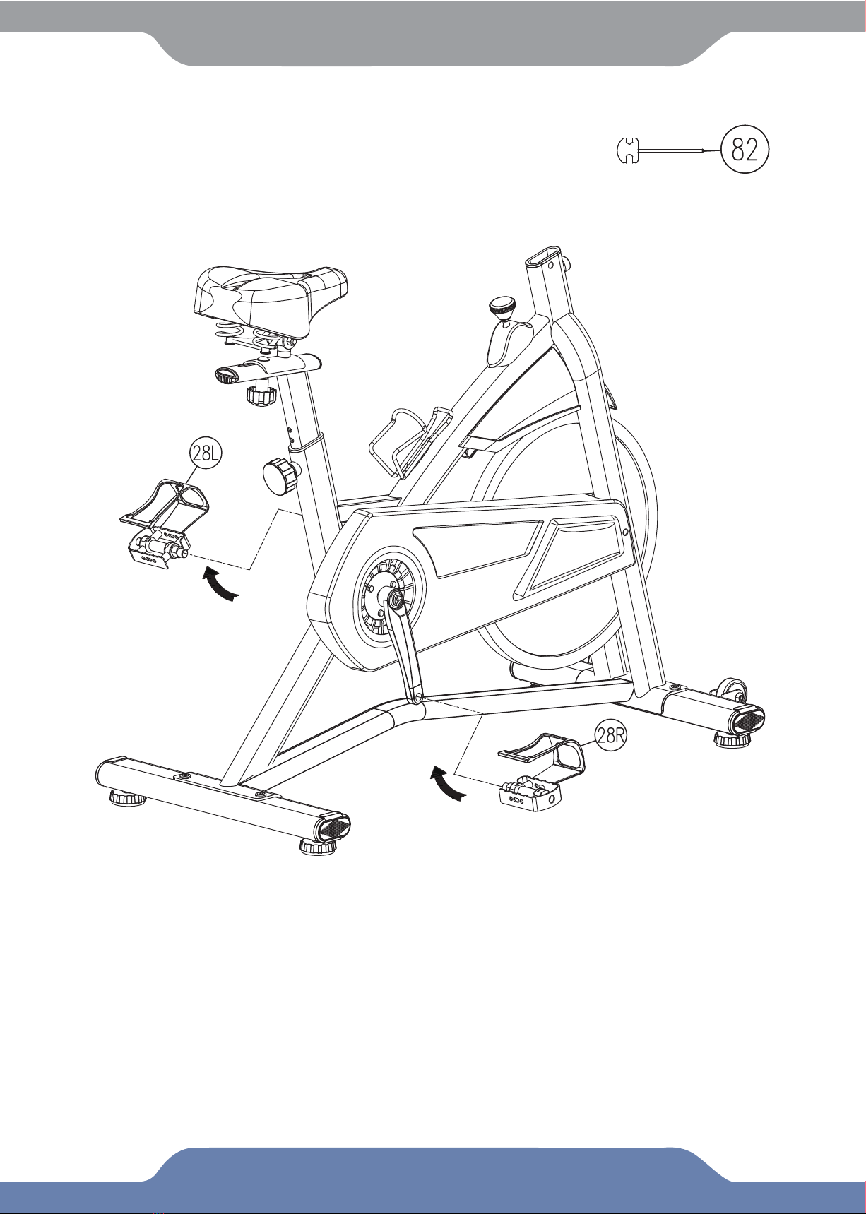
The
pedals (28L and 28R)
are marked “L” and “R”-left and right. Connect them to their appropriate
crank set(31L and 31R)
. The right crank set is on the right hand side of the cycle as you sit on it.
Note that the Right pedal should be threaded on clockwise and the left pedal on anti-clockwise.
11
ASSEMBLY INSTRUCTION
STEP 4
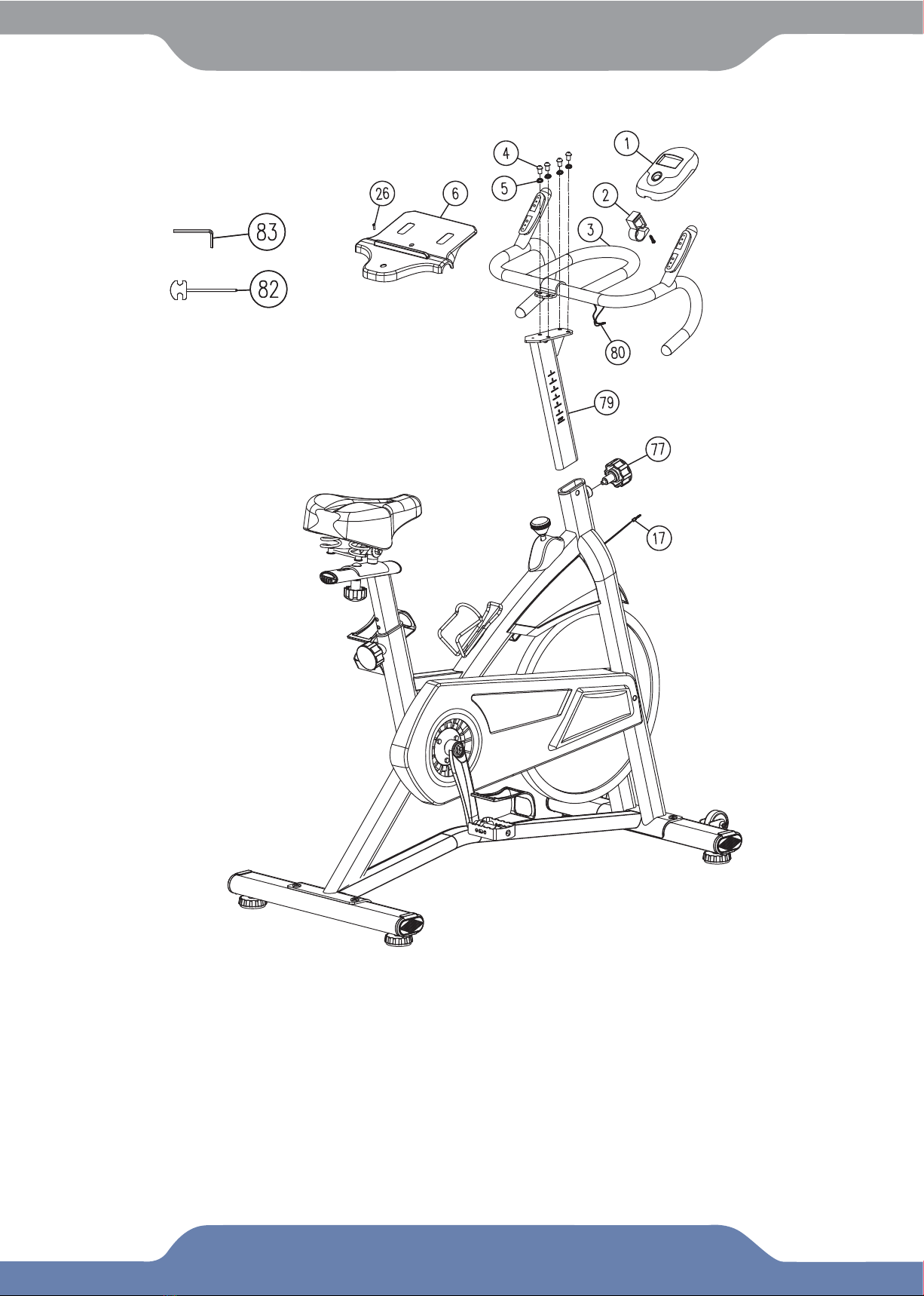
Put
Handlebar post(79)
insert Main frame with
Knob(77)
adjust height. Fix the
Handlebar(3)
on
Handlebar post using 4 sets of Hexagon
screws(4)
and Spring
washers(5)
, then cover the iPad
holder(6)
on
handlebar(3)
. Fix the computer
holder(2)
on handlebar using Screw, put
computer(1)
slip into computer holder, then insert the
sensor cable(17)
plug into the sensor joint of computer,
And insert the
pulse wire(80)
plug into the pulse joint of computer.
Now your spinning bike is finished for use.
12

EXERCISE MONITOR
13
FRONT VIEW
SPECIFICATIONS:
1. AUTO ON/OFF
2. RESET
TIME(TMR)
※ODOMETER(ODO)
※PULSE(PUL)
DISTANCE(DIST)
CALORIES(CAL)
SPEED(SPD)
00:00-99:59
0-9999KM(ML)
40-240BPM
0.00-99.99KM(ML)
0.0-999.9KCAL
0.0-99.9KM/H(ML/H)
◆The system turns on when any key is pressed or when it sensor an input from the
speed sensor.
◆The system turns off automatically when the speed has no signal input or no key
are pressed for approximately 4 minutes.
The unit can be reset by either changing battery or pressing the MODE key for 3 seconds.

EXERCISE MONITOR
14
FUNCTIONS:
SCAN:
BATTERY:
3. MODE
To choose the SCAN or LOCK if you do not want the scan mode,press the MODE key
when the pointer on the function you want which begins blinking.
Automatically display changes every 4 seconds.
If improper display on monitor,please reinstall the batteries to have a good result.
1.
TIME:
Press the MODE key until pointer lock on to TIME. The total working time will be
shown when starting exercise.
2.
SPEED:
Press the MODE key until the pointer advance to SPEED. The current speed
will be shown.
3.
DISTANCE:
Press the MODE key until the pointer advance to DISTANCE. The distance
of each workout will be displayed.
4.
CALORIE:
Press the MODE key until pointer lock on to CALORIE. The calorie burned
will be displayed when starting exercise.
5.
ODOMETER(IF HAVE):
Press the MODE key until the pointer advance to ODOEMETER.
The total accumulated distance will be shown.
6.
PULSE(IF HAVE):
Press the MODE key until the pointer advance to PULSE. User’s
current heart rate will be displayed in beats per minute. Place the palms of your hands on
both of the contact pads(or put ear-clip to ear),and wait for 30 seconds for the most accurate
reading.

Adjusting the
Foot Pad(36)
on the
Front
and
Rear Tube(53)&(38)
as needed to level the bike.
Proper leveling will reduce noises and wobbling.
ADJUSTMENTS
Rear Tube(38)
Front Tube(53)
Foot Pad(36)
15
To increase the tension, turn to
Brake Knob(7)
in a CLOCKWISE direction.
To decrease the tension, turn to
Brake Knob(7)
in a COUNTERCLOCKWISE direction.
Adjusting the Brake Knob
Brake Knob(7)

ADJUSTMENTS
Tip: When adjusting the height of Handlebar Post(79), the MAX line cannot higher than the
edge of plastic bushing.
Adjusting the Handlebar Height
Loosen the
Knob M16 (77)
by turning it COUNTER-CLOCKWISE direction until it can be pulled out.
Pull out the
Knob M16(77)
and then slide the
Seat Post(25)
up or down and settle on the desired
height. Lock the
Seat Post(25)
in place by releasing the
Knob M16(77)
and sliding the
Seat Post(25)
up or down slightly until the
Knob M16(77)
“pops” down into the locked position.For added safety,
Tighten the
Knob M16(77)
in a CLOCKWISE direction.
NOTE: When adjusting the height of seat post, the MAX line cannot higher than the edge of
plastic bushing.
Adjusting the Seat Height
16
Seat Post(25)
Knob M16(77)
Knob M16 (77)
Handlebar Post(79)
Loosen the
Knob M16 (77)
by turning it COUNTER-CLOCKWISE direction until it can be pulled out.
Pull out the
Knob M16(77)
and then slide the
Handlebar Post(79)
up or down and settle on the
desired height. Lock the
Handlebar Post(79)
in place by releasing the
Knob M16(77)
and sliding
the
Handlebar Post(79)
up or down slightly until the
Knob M16(77)
“pops” down into the locked
position. For added safety, Tighten the
Knob M16(77)
in a CLOCKWISE direction.

ADJUSTMENTS
Loosen the
Knob M10(24)
by turning it in a COUNTER-CLOCKWISE direction. Slide the
Slider(20)
in a forward direction to the suitable position. Lock the
Slider(20)
in place by turning the
Knob
M10(24)
in a CLOCKWISE direction.
Adjusting the Seat Forward or Back
17
Knob M10(24)
Slider(20)
You can scan this QR code toenter
into our Youtube page to follow the
product assemblyvideos.
Hope it will be helpful for you.
Assembly Instruction Video

TROUBLE SHOOTING
18
1.
PROBLEM:
The bike wobbles when in use.
1)
SOLUTION:
Turn the
Foot Pads (36)
on the
Rear
and
Front Tube (38) & (53)
or as needed
to level the bike.
2.
PROBLEM:
The display on the
Computer (1)
does not turn on.
1)
SOLUTION:
Remove the
Computer (1)
and verify that the wires from the
Computer (1)
are
properly connected to the wires of the
Handlebar Post (79)
.
3.
PROBLEM:
Not displaying/inconsistent/erratic heart rate readings
1)
SOLUTION:
Always hold onto the
Hand Pulse (81)
with both hands. Maintain moderate
pressur when holding onto the
Hand Pulse (81)
.
2)
SOLUTION:
Make sure the wire connections for the
Pulse Wires (80)
.
3)
SOLUTION:
Wipe your excess moisture off your hands.
4.
PROBLEM:
The bike makes a squeaking noise when in use.
1)
SOLUTION:
The bolts may be loose on the recumbent bike. Inspect all of the bolts and tighten
any loose bolts.
MAINTENANCE
1. The bike can be cleaned with a soft clean damp cloth.
2.
Do not
use abrasives or solvents on the plastic parts.
3. Wipe your perspiration off the bike after each use.
4. Be careful not to get excessive moisture on the Console display as this might cause an
electrical hazard or the electronics to fail.
5. Keep the bike, especially the computer console out of direct sunlight to prevent screen
damage.
6.Be sure all assembly bolts, nuts, screws, and pedals on the machine are thoroughly tightened
prior to use. Tighten any loose parts.
Table of contents
Other snode Exercise Bike manuals


