SnowEx RDV V-Plow User manual

June 15, 2020
Lit. No. 30118, Rev. 00
MECHANIC'S GUIDE
for the
RDV™V-Plow
CAUTION
Read this manual before servicing the snowplow.
SNOWPLOWS


Lit. No. 30118, Rev. 00 June 15, 2020
TABLE OF CONTENTS
INTRODUCTION ..............................................................................................4
Recommended Tools...................................................................................4
Available Service Items ...............................................................................4
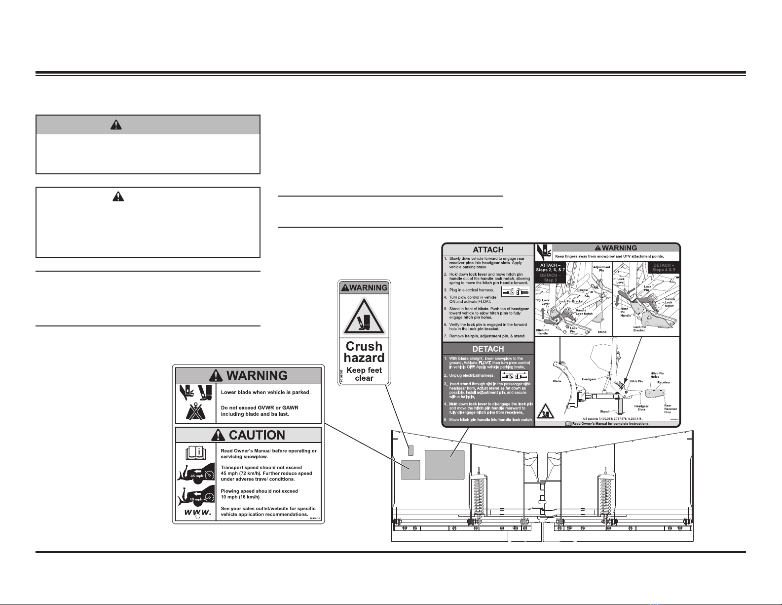
SAFETY ............................................................................................................5
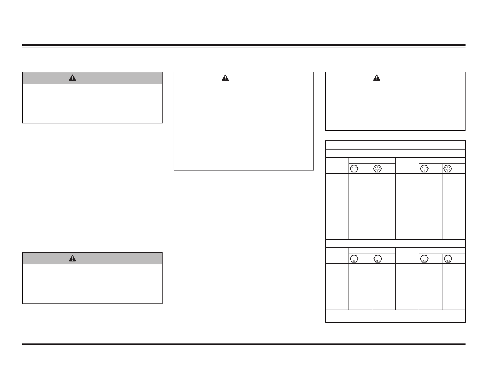
Torque Chart ................................................................................................7
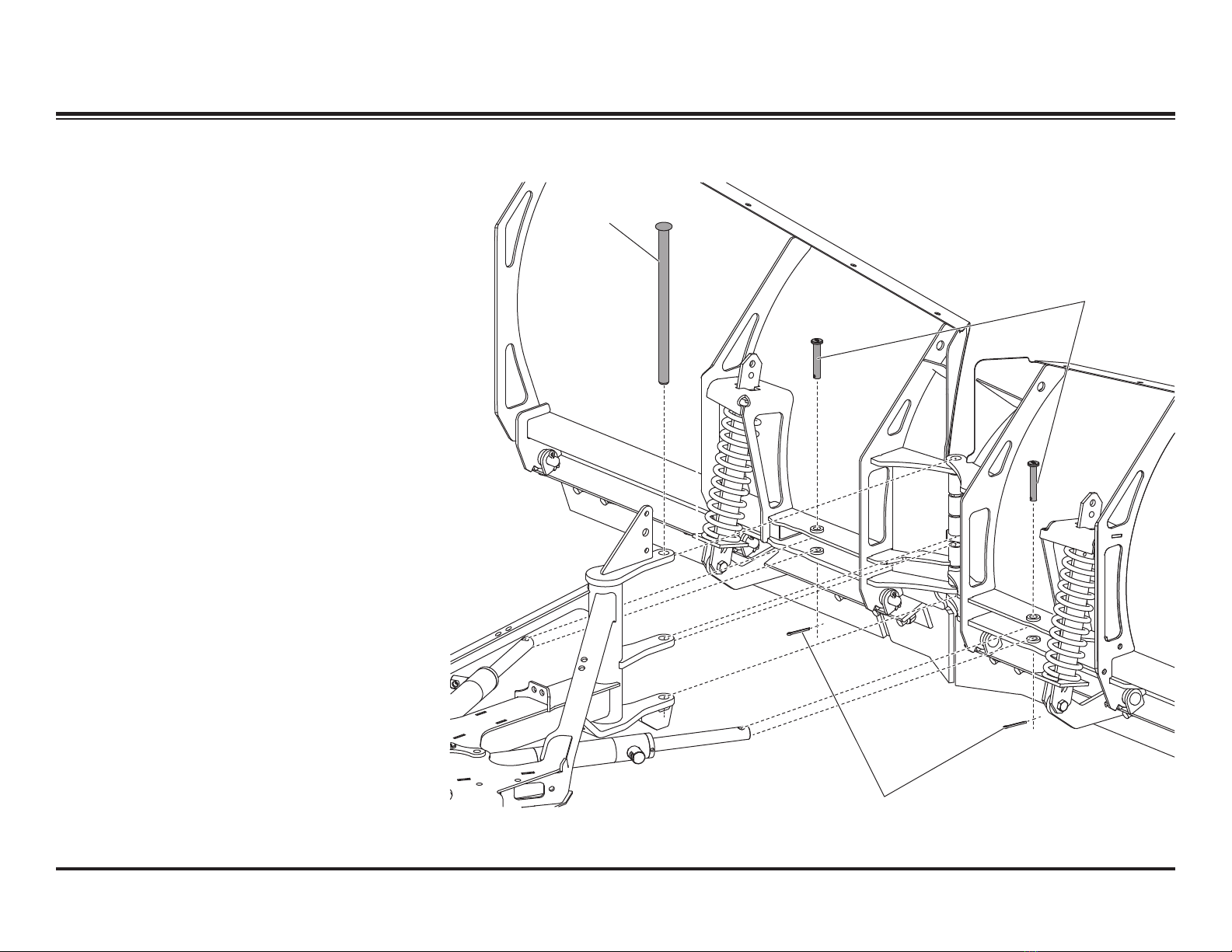
BLADE, T-FRAME & HEADGEAR.................................................................8
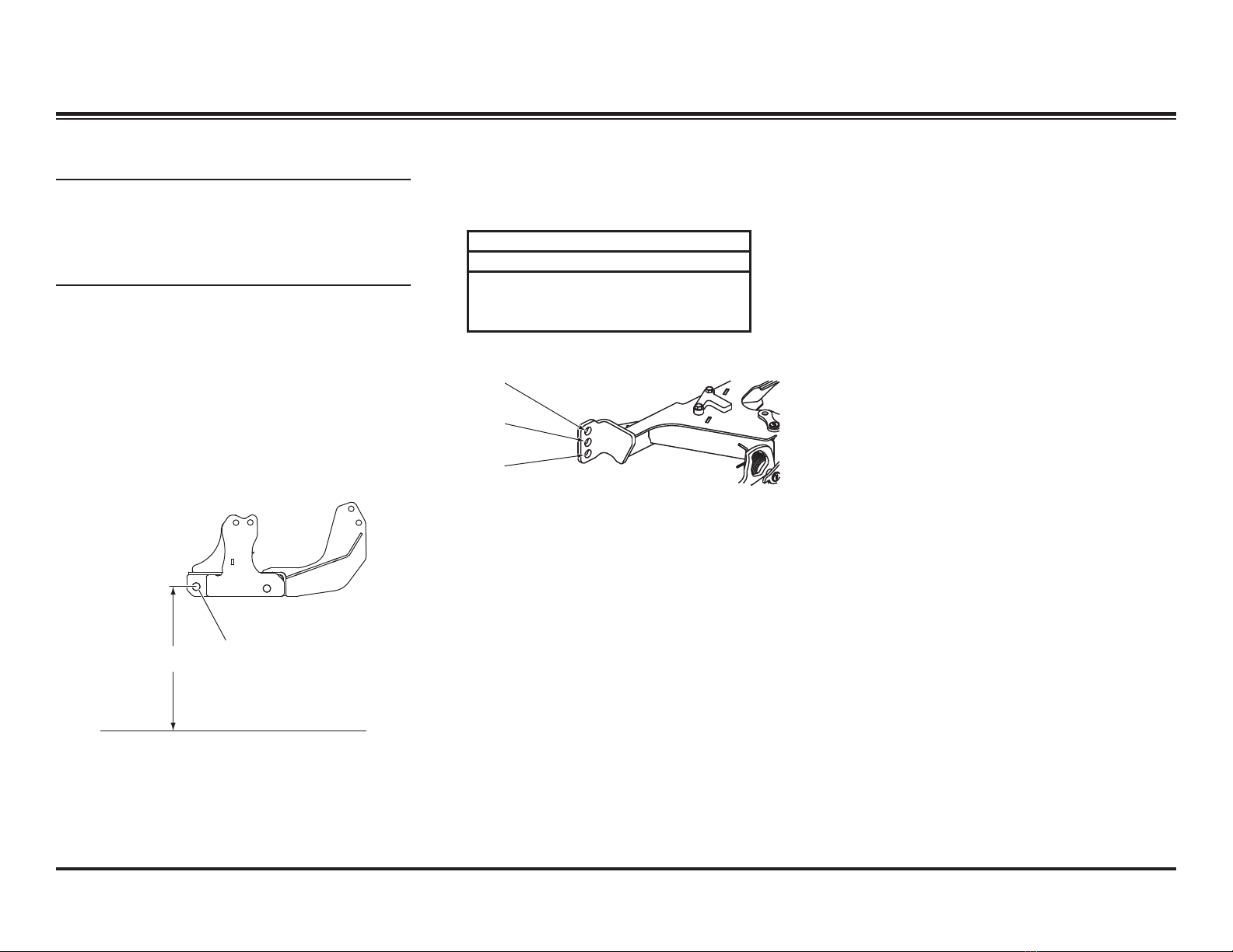
T-Frame Hole Position .................................................................................8
T-Frame to Blade Assembly ........................................................................9
Center Deflector, Blade Guides, and Angle Ram Adjustment ...................11
Using the Blade Spring Replacement Tool ................................................12
HYDRAULIC SYSTEM ..................................................................................13
Hydraulic System Specifications................................................................13
Hydraulic Unit Components .......................................................................14
Valve Location ...........................................................................................15
Cartridge Valves ........................................................................................16
Check Valves and Relief Valves ................................................................17
Hydraulic Fitting and Hose Installation ......................................................18
Ram Seal Installation.................................................................................19
Cartridge and Check Valve Removal........................................................ 20
Blade Drop Speed Adjustment ................................................................. 20
VEHICLE-SIDE ELECTRICAL COMPONENTS .........................................21
Harness Diagram.......................................................................................21
Harness Diagram – LED Headlamps........................................................ 22
CONTROLS – FLEET FLEX ELECTRICAL SYSTEM............................... 23
Overview................................................................................................... 23
Operating the POWER GRIP™ Hand-Held Control..................................24
Operating the Joystick Control.................................................................. 26
FLEET FLEX ELECTRICAL SYSTEM .........................................................28
Smooth Stop and One-Touch Float Features ............................................28
SECURITY GUARD™ Snowplow Anti-Theft System ............................... 29
ELECTRICAL & HYDRAULIC SCHEMATICS............................................32
Legend – Electrical & Hydraulic Symbols..................................................32
Electrical Schematic – RDV™ V-Plow...................................................... 33
Hydraulic Schematic – RDV V-Plow ......................................................... 34
Raise......................................................................................................... 35
Lower/Float ................................................................................................37
Angle Right .............................................................................................. 39
Angle Left ..................................................................................................41
BUCKET BLADE™ (Vee) ......................................................................... 43
Compact (Scoop) ...................................................................................... 45
Right (PS) Wing Extend .............................................................................47
Right (PS) Wing Retract............................................................................ 49
Left (DS) Wing Extend ...............................................................................51
Left (DS) Wing Retract.............................................................................. 53
Hold in Raise Position .............................................................................. 55
Striking an Object While Plowing Forward ............................................... 56
Striking an Object While Back Dragging....................................................57
Detach....................................................................................................... 58
Attach........................................................................................................ 59
Scrape Maxx™ Down Force Kit................................................................ 60
Headlamps.................................................................................................62
Electrical/Harnesses...............................................................................62
Electrical Schematics ............................................................................ 63
TROUBLESHOOTING.................................................................................. 69
How to Use the Troubleshooting Guide .....................................................70
Electrical Testing........................................................................................70
Fuse Replacement.....................................................................................70
Before You Begin .......................................................................................71
Solenoid Coil Activation Test (SCAT).........................................................72
Individual Solenoid Coil Test......................................................................75
Control/Cable/Plow Module Test ...............................................................76
Motor and Motor Relay Test...................................................................... 77
Pump Pressure Test ..................................................................................78
Relief Valve Inspection and Adjustment ....................................................79
Scrape Lock Adjustment........................................................................... 80
Replacing Damaged Bearing Sleeves .......................................................82

Lit. No. 30118, Rev. 00 June 15, 2020
4
This guide has been prepared to assist the
trained mechanic in the service of SnowEx®
RDV™ V-plows. It also provides safety information
and recommendations. We urge all mechanics to
read the safety statements and instructions in this
guide carefully before attempting to service the
snowplow equipment covered by this guide.
Service of your SnowEx snowplow equipment is
best performed by your local SnowEx products
dealer. They know your snowplow best and are
interested in your complete satisfaction.
INTRODUCTION
RECOMMENDED TOOLS
• Long/slender needle-nose pliers
• Flat screwdriver
• 12V test light
• Torque wrench
• Hex key set, including 3/8"
• Combination standard wrench set
• 1/4" drive ratchet set with 6" extension
• 3/8" drive ratchet set
• Deep socket: 7/8"
• Digital volt/ohmmeter
• Ammeter
• Pressure test kit
• Flashlight
• Pick set
• Hammer
• Pencil magnet
• 5A mini fuses
• Vacuum pump with 3/8" NPT barbed fitting
• 3/8" NPT plug
AVAILABLE SERVICE ITEMS
• Motor Bearing Sleeve Repair Kit: PN 52251
(Requires 3/8"-24 x 4" cap screw, not
included.)
• Pressure Test Kit: PN 56686
(Requires adapter fitting, not included.)
• Spring Replacement Tool: PN 20043-1
• Diagnostic Harness Kit: PN 29290-2
• Pump Shaft Seal Repair Kit: PN 28856
(Requires 1/4"-28 x 4-1/2" cap screw, not
included.)

Lit. No. 30118, Rev. 00 June 15, 2020
5
NOTE: Indicates a situation or action that can
lead to damage to your snowplow and vehicle
or other property. Other useful information can
also be described.
SAFETY
WARNING/CAUTION AND
INSTRUCTION LABELS
Become familiar with and inform users about the
warning and instruction labels on the back of the
blade.
NOTE: If labels are missing or cannot be read,
see your local SnowEx®dealer.
CAUTION
Indicates a potentially hazardous situation
that, if not avoided, may result in minor
or moderate injury. It may also be used to
alert against unsafe practices.
WARNING
Indicates a potentially hazardous situation
that, if not avoided, could result in death or
serious personal injury.
SAFETY DEFINITIONS
Warning/Caution Label
Instruction Label
Warning Label

Lit. No. 30118, Rev. 00 June 15, 2020
6
SAFETY
SAFETY PRECAUTIONS
Improper installation and operation could cause
personal injury, and/or equipment and property
damage. Read and understand labels and the
Owner's Manual before installing, operating, or
making adjustments.
HYDRAULIC SAFETY
• Always inspect hydraulic components and
hoses before using. Replace any damaged or
worn parts immediately.
• If you suspect a hose leak, DO NOT use your
hand to locate it. Use a piece of cardboard or
wood.
WARNING
Lower the blade when vehicle is parked.
Temperature changes could change
hydraulic pressure, causing the blade to
drop unexpectedly or damaging hydraulic
components. Failure to do this could result
in serious personal injury.
WARNING
Remove blade assembly before placing
vehicle on hoist.
WARNING
The driver shall keep bystanders clear of
the blade when it is being raised, lowered,
or angled. Do not stand between vehicle
and blade or within 8 feet of a moving blade.
A moving or falling blade could cause
personal injury.
WARNING
Do not exceed GVWR or GAWR including
blade and ballast. The rating label is found
on driver-side vehicle door cornerpost.
WARNING
To prevent accidental movement of
the blade, always turn the control OFF
whenever the snowplow is not in use. The
power indicator light will turn OFF.
WARNING
Keep hands and feet clear of the blade and
T-frame when mounting or removing the
snowplow. Moving or falling assemblies
could cause personal injury.
CAUTION
Refer to the current online selection system
for minimum vehicle recommendations
and ballast requirements.
WARNING
Hydraulic fluid under pressure can cause
skin injection injury. If you are injured
by hydraulic fluid, get medical attention
immediately.
FUSES
The electrical and hydraulic systems contain
several automotive-style fuses. If a problem should
occur and fuse replacement is necessary, the
replacement fuse must be of the same type and
amperage rating as the original. Installing a fuse
with a higher rating can damage the system and
could start a fire. See the Troubleshooting section
of this guide for fuse replacement information.
PERSONAL SAFETY
• Remove ignition key and put the vehicle in
PARK or in gear to prevent others from starting
the vehicle during installation or service.
• Wear only snug-fitting clothing while working
on your vehicle or snowplow.
• Do not wear jewelry or a necktie, and secure
long hair.
• Wear safety goggles to protect your eyes from
battery acid, gasoline, dirt, and dust.
• Avoid touching hot surfaces such as the
engine, radiator, hoses, and exhaust pipes.
• Always have a fire extinguisher rated BC
handy, for flammable liquids and electrical
fires.

Lit. No. 30118, Rev. 00 June 15, 2020
7
TORQUE CHARTBATTERY SAFETY
NOISE
Airborne noise emission during use is below
70 dB(A) for the snowplow operator.
VIBRATION
Operating snowplow vibration does not exceed
2.5 m/s2to the hand-arm or 0.5 m/s2to the whole
body.
FIRE AND EXPLOSION
Be careful when using gasoline. Do not use
gasoline to clean parts. Store only in approved
containers away from sources of heat or flame.
CELL PHONES
A driver's first responsibility is the safe operation
of the vehicle. The most important thing you can
do to prevent a crash is to avoid distractions and
pay attention to the road. Wait until it is safe to
operate mobile communication equipment such as
cell phones, text messaging devices, pagers, or
two-way radios.
VENTILATION
SAFETY
1/4-20 109 154
1/4-28 121 171
5/16-18 150 212
5/16-24 170 240
3/8-16 269 376
3/8-24 297 420
7/16-14 429 606
7/16-20
9/16-12
9/16-18
5/8-11
5/8-18
3/4-10
3/4-16
7/8-9
7/8-14 474 669
644 9091-8
1-12 704 995
1/2-13
1/2-20
11.9
13.7
24.6
27.3
43.6
26.9
53.3
93
148
49.4
69.8
77.9
106.4
120.0
8.4
9.7
17.4
19.2
30.8
35.0
49.4
55.2
75.3
85.0
M6 x 1.00
M12 x 1.75
M8 x 1.25
M14 x 2.00
M10 x 1.50
M27 x 3.00
M22 x 2.50
M30 x 3.50
M24 x 3.00
M20 x 2.5011.1
19.5
38.5
67
107
7.7
613
778
1139
1545
450
428
562
796
1117
M33 x 3.50
M36 x 4.00
2101
2701
1468
1952
325
M16 x 2.00 231
167
M18 x 2.50 318222
Recommended Fastener Torque Chart
Size Size
Torque (ft-lb)
Grade
5
Grade
8
Metric Fasteners Class 8.8 and 10.9
These torque values apply to fasteners
except those noted in the instructions.
Torque (ft-lb)
Grade
5
Grade
8
Size Size
Torque (ft-lb)
Class
8.8
Class
10.9
Torque (ft-lb)
Class
8.8
Class
10.9
Inch Fasteners Grade 5 and Grade 8
CAUTION
Batteries normally produce explosive
gases, which can cause personal injury.
Therefore, do not allow flames, sparks, or
lit tobacco to come near the battery. When
charging or working near a battery, always
cover your face and protect your eyes, and
also provide ventilation.
• Batteries contain sulfuric acid, which
burns skin, eyes, and clothing.
• Disconnect the battery before removing
or replacing any electrical components.
CAUTION
Read instructions before assembling.
Fasteners should be finger tight until
instructed to tighten according to torque
chart. Use standard methods and practices
when attaching snowplow, including proper
personal protective safety equipment.
WARNING
Gasoline is highly flammable and gasoline
vapor is explosive. Never smoke while
working on vehicle. Keep all open flames
away from gasoline tank and lines. Wipe
up any spilled gasoline immediately.
WARNING
Vehicle exhaust contains lethal fumes.
Breathing these fumes, even in low
concentrations, can cause death. Never
operate a vehicle in an enclosed area
without venting exhaust to the outside.

Lit. No. 30118, Rev. 00 June 15, 2020
8
T-FRAME HOLE POSITION
IMPORTANT! Before assembling the headgear
to the T-frame, the T-frame hole position must
be determined using the following procedure.
(If the truck is not available, use the middle
position. Adjustments can be made later.)
Before measuring the vehicle mount height, the
vehicle mount must be installed, ballast must
be installed, if required, and the vehicle must be
parked on a level surface.
1. Measure the distance "d" from the ground to
the center of the hole in the vehicle mount.
Measure the distance on both sides of the
vehicle and determine average value for "d."
Center of Hole
in Vehicle Mount
d
BLADE, T-FRAME & HEADGEAR
2. Use distance "d" from Step 1 and the following
chart to determine the proper T-frame hole.
T-Frame Hole Chart
Distance "d" Hole
14.25" – 15.5" 1
13.0" – 14.25" 2
11.75" – 13.0" 3
Hole 1
Hole 2
Hole 3

Lit. No. 30118, Rev. 00 June 15, 2020
9
BLADE, T-FRAME & HEADGEAR
T-FRAME TO BLADE ASSEMBLY
1. Position the T-frame between the headgear
strut and inner ear, aligned with the appropriate
T-frame hole.
2. On each side, insert 3/4" x 3-1/4" clevis
pins (from the shipping bracket) from the
outside of the headgear through the correct
T-frame holes. Secure the clevis pins with
5/32" x 1-1/2" cotter pins found in the parts
bag.
Based on Installation Instructions for RDV™ V-Plow (Lit. No. 74912, Rev. 00).
3. Fold the headgear forward and pin
the lift cylinder to the T-frame using a
1/2" x 2-1/8" clevis pin and 5/32" x 1-1/2" cotter
pin from the parts bag.
3/4" x 3-1/4"
Clevis Pin
5/32" x 1-1/2"
Cotter Pins
1/2" x 2-1/8"
Clevis Pin
3/4" x 3-1/4"
Clevis Pins
Stacking Stop
3/4" Locknuts
4. If the T-frame was installed into the top hole,
install the stacking stops using
3/8” x 1-1/4” cap screws and 3/8” locknuts.

Lit. No. 30118, Rev. 00 June 15, 2020
10
BLADE, T-FRAME & HEADGEAR
T-FRAME TO BLADE ASSEMBLY
1. Remove the blade wings from the crate.
Remove the four shipping straps, then replace
the cutting edge hardware.
2. Align the hinges of each wing. Position the
T-frame assembly between the blade wings so
the holes in the T-frame are aligned with the
holes in wing hinges.
3. Insert the pivot pin from top to bottom through
all hinges as shown.
4. Move the snowplow into a normal operating
position.
5. Remove the protective packaging from the
angle rams.
6. Align the holes in the rod end of the angle ram
with the corresponding holes on the back of
the blade.
7. Install a 1/2" x 2-7/8" clevis pin (from the
shipping bracket) from the top down to
attach each rod. Secure the clevis pins with
5/32" x 1-1/2" cotter pins from the parts bag.
Pivot Pin
1/2" x 2-7/8"
Clevis Pins
5/32" x 1-1/2" Cotter Pins

Lit. No. 30118, Rev. 00 June 15, 2020
11
BLADE, T-FRAME & HEADGEAR
Pivot
Pin
3/8" x 1-1/2"
Cap Screw
3/8"
Locknut
Blade
Guide
5/16"
Locknuts
5/16" x 1"
Cap Screws
8. Install the center snow deflector using two
3/8" x 1-1/2" cap screws and 3/8" locknuts.
9. Install the blade guides with 5/16" x 1" cap
screws and 5/16" locknuts, as shown.
CENTER DEFLECTOR AND BLADE GUIDES ANGLE RAM ADJUSTMENT –
RDV™ BLADE
The RDV V-plow has adjustable angle rams with
two possible mounting positions at the base end
of each ram, nearest the vehicle. This feature
provides a means for making an adjustment in
available ground clearance for when the snowplow
is fully raised and in full angled or retracted (vee)
positions. The angle rams are installed from the
factory in the inner holes (position A). If additional
ground clearance is desired, reposition the
rams to position B, being sure to use the same
corresponding hole for attaching each ram.
NOTE: Failure to make the adjustment or
failure to use the same corresponding holes
for attaching the rams could result in poor
performance or damage.
Position A
Position B

Lit. No. 30118, Rev. 00 June 15, 2020
12
BLADE, T-FRAME & HEADGEAR
USING THE BLADE SPRING REPLACEMENT TOOL
1. Park the vehicle on a smooth, level, hard
surface, such as concrete. Lower the blade
to the ground and turn the control OFF.
Disconnect the snowplow from the vehicle or
turn the vehicle ignition to the "OFF" position
and remove the key.
2. The spring replacement tool (PN 20043-1)
ships fully assembled. Before using the tool,
apply a light coating of multipurpose grease to
the threaded end of the spade bolt.
3. Place the tool on the top anchor above the
spring, making sure that the upper end of the
spring bar is between the clevis tabs of the
spring replacement tool. Insert a 1/2" x 2" cap
screw through the lower hole in one clevis tab,
through the top hole in the spring bar, then the
hole in the other clevis tab. Install a 1/2" nut
and hand tighten.
1/2" x 2" cap screw
inserted through clevis
and spring bar.
Spring Bar
Top Anchor
1/4" x 1-1/4" Pin
5/8" Hex
Nut
4. Use hand tools to tighten the 5/8" hex nut until
the spring bar is raised enough to access the
pin hole. Insert the 1/4" x 1-1/4" pin through the
pin hole, centering the pin from side to side.
5. Loosen the 5/8" hex nut to lower the spring bar.
Remove the spring tool assembly by removing
the 1/2" cap screw inserted through the spring
bar in Step 3.
6. Detach the spring from the blade by removing
the shoulder bolt and locknut at the bottom of
the spring bar. Retain the fasteners.
7. Insert the replacement spring with spring bar
up through the top anchor on the blade. Install
the bottom of the spring bar to the anchor on
the trip edge using the retained shoulder bolt
and locknut. Tighten to 50 ft-lb.
8. Repeat Step 3.
9. Use hand tools to tighten the 5/8" hex nut until
the spring bar is raised enough to access the
1/4" x 1-1/4" pin inserted in Step 4. Remove
the pin.
10. Repeat Step 5.
Frame
Clevis
Grease spade
bolt threads.

Lit. No. 30118, Rev. 00 June 15, 2020
13
Hydraulic Fluid
Use SnowEx®Hydraulic Fluid to –40°F (–40°C)
or other fluid conforming to military specification
MIL-H-5606 A, such as Mobil Aero HFA or Shell
AeroShell®Fluid 4. Use of products other than
these recommended fluids may cause poor
hydraulic system performance and damage to
internal components.
The hydraulic system delivers fast and uniform
speed for blade movement, raising the blade in two
seconds and performing all angling functions in
less than five seconds.
Relief Valve Settings
• Pump Relief Valve (1): 2250 ± 100 psi
1-3/4 turns CCW from fully seated
• Base-End Relief Valves (2): 3400 ± 100 psi
1-1/8 turns CCW from fully seated
• Rod-End Relief Valves (2): 2200 ± 100 psi
1-3/4 turns CCW from fully seated
• Scrape Lock Relief Valve (1): 210 psi
1-3/4 turns CCW from fully seated
Pump Motor
12V DC with +/– Connection
3.0" dia. 0.8 kW Motor
2200–2300 psi Pump Relief Valve
3400 psi Plowing Relief Valves
2200 psi Back Dragging Relief Valves
0.000477 gal/rev Pump
Hydraulic Hose 1/4 SAE 100R1
System Capacity
• Unit reservoir: 1-3/4 quarts
• System total: 2-1/8 quarts
HYDRAULIC SYSTEM
CAUTION
Do not mix different types of hydraulic fluid.
Some fluids are not compatible and may cause
performance problems and product damage.
AeroShell®is a registered (®) trademark of Shell Oil Company.
HYDRAULIC SYSTEM SPECIFICATIONS
Electrical System (Approximate Values)
• Solenoid Coil Resistance = 7 ohm @ room temp.
• Solenoid Coil Amperage Draw = 1.5A
• Motor Relay Coil Resistance = 5.4 ohm
• Motor Relay Amperage Draw = 3A
• Maximum Motor Amperage Draw = 190A over
relief at 2250 psi
• Switch Accessory Lead Draw = 0.75A
Fuses
• Hydraulic Unit Harness Fuses: 5A mini
Fastener Torque Specifications
Pump Cap Screws 5/16-18 x 2-1/4 150–160 in-lb
Motor Terminals (+ and –) 5/16-18 Nut 50–60 in-lb
Motor to Manifold Cap Screws M5 x .8 Bolt 30–40 in-lb
Reservoir Screws #10-24 x 5/16 30–35 in-lb
Solenoid Valves 7/8 Hex Head 19–21 ft-lb
Coil Nuts 3/4 Hex-Head Jam Nut 40–60 in-lb
SAE O-Ring Plugs 1/8 or 5/32 Internal Hex 55–65 in-lb
Hydraulic Unit Mount Bolts 3/8-16 x 1 25–33 ft-lb
Check Valves 7/8 Hex Head 19–21 ft-lb
Secondary to Primary Manifolds 1/4-20 x 3-1/2 7–9 ft-lb
Motor Relay Small Terminals #10-32 Nut 15 in-lb max
Motor Relay Large Terminals 5/16-24 Nut 35 in-lb max
Motor Relay Mount Screws 1/4-20 x 3/8 60–70 in-lb
Plow Module Mount Screws 1/4-20 x 3/8 60–70 in-lb
Angle Ram –4 Elbow Fitting Nut 11–12 in-lb
Angle Ram Piston Locknuts 90–100 ft-lb
Lift Ram Piston Nut 90–100 ft-lb
Angle Ram Gland Nuts 120–150 ft-lb
Lift Ram Gland 30–40 ft-lb

Lit. No. 30118, Rev. 00 June 15, 2020
14
HYDRAULIC UNIT COMPONENTS
Breather
Reservoir
Plug
Magnet
O-Ring
Suction
Filter
Plow
Module
Module
Plate
Primary
Manifold
Motor
Motor
Relay
Check
Valves
Coil
w/Spades
Relief
Valve
Relief
Valve
Check
Valves
4-Way
Valve
Coil
w/Spades
Relief
Valve
Coil
w/Spades
4-Way
Valve
Quill
2-Way
Valves
Relief Valve
Coil
w/Spades
4-Way
Valve
O-Rings
O-Ring
Pressure
Switch
HYDRAULIC SYSTEM
Reservoi
r
Breather/Fill Plug
Valve Manifold
Quill
Drain Plug
Motor

Lit. No. 30118, Rev. 00 June 15, 2020
15
VALVE LOCATION
HYDRAULIC SYSTEM
P10
Lift Ram
Base
CV5
P2
Right Rod
P1
Right
Base
S2C2
S2C1
S6C2
S6C1
RV6
PS Base
End Relief
RV5
DS Base
End
Relief
CV1 CV2
P3
Left Rod
P4
Left Base
S3
S5C2
S5C1
S4
RV2
Lift
Cylinder
Base
S1
P5
Lift Ram
Rod
CV6
RV3
DS Rod End
Relief
RV1
Pump
Pressure
RV4
PS Rod End
Relief
Quill
CV3
CV4 PC1 PC2
Solenoid Cartridge Valves
Coil Valve Type Wire Color
S1 SV08-2211 Pink
S2C1 SV08-47D Dark Green
S2C2 Purple
S3 SV10-43 Yellow
S4 SV08-2211 Blue
S5C1 SV08-47C Black
S5C2 Orange
S6C1 SV08-47C Brown
S6C2 White

Lit. No. 30118, Rev. 00 June 15, 2020
16
HYDRAULIC SYSTEM
CARTRIDGE VALVES
The RDV™ V-plow hydraulic system performs ten
blade movement functions.
All functions require the vehicle ignition (key) switch
to be in the "RUN" or "ACCESSORY" position and
the power to be activated on the snowplow cab
control.
Blade Movement
Solenoid ATTACH DETACH
Scrape
Maxx™
FEATURE
(OPT)
Motor M ON ON ON ON ON ON ON ON ON ON ON ON
SV08-2211 S1 ON ON ON
SV08-47D S2C1 ON ON
S2C2 ON
SV10-43 S3 ON ON
SV08-2211 S4 ON ON ON
SV08-47C S5C1 ON ON ON
S5C2 ON ON ON
SV08-47C S6C1 ON ON
S6C2 ON ON
VEE SCOOP EXTEND
LEFT
ANGLE
LEFT
ANGLE
RIGHT
RAISE LOWER
RIGHT
RETRACT
RIGHT
EXTEND
LEFT
RETRACT
Nine of the ten hydraulic functions require
energizing the electric motor and opening solenoid
cartridge valves. The LOWER function does not
energize the motor but requires the opening of
one cartridge valve.
Power from the vehicle battery is supplied to the
solenoid coils and the motor relay via the plow
module. The solenoid cartridge valves operate in
various combinations, directed by the cab control,
to send hydraulic fluid to the snowplow lift and
angle rams or back to the reservoir. (Power is
supplied to the plow module via the battery cable
and motor relay connection.)

Lit. No. 30118, Rev. 00 June 15, 2020
17
HYDRAULIC SYSTEM
CHECK VALVES
The check valves supply make-up fluid to the
low-pressure side of a ram that is extending or
retracting through a relief valve due to impact on
one or both wings.
A pilot-operated check valve (PC) allows fluid to flow
in only one direction unless it receives pilot pressure
through another circuit to shift it to an open position.
Tighten check valves to 19–21 ft-lb.
Relief Valve Settings
RV1 Pump 2250 ± 100 psi
RV3 DS Ram Rod End 2200 ± 100 psi
RV4 PS Ram Rod End
RV5 DS Ram Base End 3400 ± 100 psi
RV6 PS Ram Base End
RELIEF VALVES
When all cartridge valves are closed, hydraulic
fluid is trapped in the ram by the solenoid cartridge
valves, check valves, base-end relief valves, and
rod-end relief valves.
When the snowplow contacts an object while
plowing, force of the impact increases hydraulic
pressure in the base end of the ram. When
pressure exceeds 3400 psi, the ram's base-end
relief valves open, allowing hydraulic fluid back to
the reservoir. Due to the small volume on the rod
side of the piston, fluid is not replaced. This causes
a slight temporary vacuum in that circuit.
When the snowplow contacts an object while back
dragging, force of the impact increases hydraulic
pressure in the rod end of the ram. When pressure
exceeds 2200 psi, the ram's rod-end relief valve
opens, allowing hydraulic fluid into the reservoir
passage. The base-end check valve allows fluid to
fill the base end of the ram. Because of differential
area on either side of the ram's piston, fluid flows
from the reservoir to the base end.
NOTE: See "Striking an Object While Plowing
Forward" and "Striking an Object While Back
Dragging" schematics for details.
Check Valves
CV1
CV08-2004
CV2
CV3
CV4
CV5 CV08-2059
Primary
Manifold
CV5
Secondary
Manifold
CV3
CV4
CV6
CV2
CV1
Primary
Manifold
Secondary
Manifold
RV3
RV1
Pressure
Test Port
RV4
RV5
RV6

Lit. No. 30118, Rev. 00 June 15, 2020
18
HYDRAULIC SYSTEM
NOTE: Overtightening JIC hose fitting ends will
result in a fractured fitting.
DO NOT use thread sealant/tape on hydraulic
hoses or fittings. These materials could damage
the product. Always use two wrenches to ensure
proper tightening of fittings and hoses.
To install SAE O-ring fittings in the valve block
and rams:
1. Turn the jam nut on the fitting as far back as
possible.
2. Lubricate the O-ring with clean hydraulic fluid.
3. Screw the fitting into the port by hand until the
washer contacts the port face and the shoulder
of the jam nut threads.
4. Unscrew the fitting to its proper position; no
more than one full turn.
5. Using two wrenches, hold the fitting body
in position and tighten the jam nut until the
washer again contacts port face, then tighten
an additional 1/8 to 1/4 turn to lock the fitting
in place. Final torque on the jam nut should be
approximately 20 ft-lb.
To install hydraulic hoses:
1. Screw the flare nut onto the fitting flare and
hand tighten it.
2. Align the hose so that there are no twists or
sharp bends and so that it will not be pinched
or pulled by moving parts.
3. Using a pair of adjustable pliers, hold the
hose in position, and use a wrench to tighten
the flare nut 1/8 to 1/4 turn beyond hand
tight. Final torque on the flare nut should be
approximately 20 ft-lb.
4. Reinstall any protective hose wraps in their
original positions.
HYDRAULIC FITTING AND HOSE INSTALLATION
Lift Ram Base
Lift Ram Rod
Left (DS) Base
Right Rod
Right
(PS)
Base
Lift Rod
Angle Ram
90º Elbow
90º Elbow
–4 Elbow
Lift Ram

Lit. No. 30118, Rev. 00 June 15, 2020
19
RAM SEAL INSTALLATION
HYDRAULIC SYSTEM
1. Lubricate the O-rings with hydraulic fluid
before assembly.
2. Assemble the gland components as shown,
then lubricate them with hydraulic fluid.
3. Remove the piston from the rod and assemble
the piston components as shown.
4. Assemble the gland to threaded end of the rod.
Do not slide the gland over the cross hole in
the rod.
5. Reassemble piston to rod and tighten the nut:
• 90–100 ft-lb for angle ram
• 90–100 ft-lb for lift ram.
6. Assemble the O-ring into the groove on the
rod. Use tape or other protection on the
threads.
7. Apply a bead of medium-strength threadlocker
all around the threads of the gland.
8. Lubricate the piston seals and the inside of the
cylinder.
9. Press the rod assembly into the cylinder and
tighten the gland nut:
• 120–150 ft-lb for the angle ram
• 30–40 ft-lb for the lift ram.
Nut
Groove
in Rod
Rod
Gland
Piston
Cylinder
Seal Position
Gland
Back-Up Ring
Wiper
Seal
O-Ring
Wear Ring Inner
Backing
Ring
Outer
Seal
Wear
Ring
GLAND SECTION PISTON SECTION

Lit. No. 30118, Rev. 00 June 15, 2020
20
1. Lower the blade to the ground before making
any adjustment.
2. Remove the hydraulic unit cover.
3. The quill in the valve manifold adjusts the
blade drop speed. Turn the quill IN (clockwise)
to decrease drop speed. Turn the quill OUT
(counterclockwise) to increase drop speed.
4. Stand 8 feet clear of the blade when checking
the drop speed adjustment.
5. Replace the hydraulic unit cover.
CARTRIDGE & CHECK VALVE REMOVAL BLADE DROP SPEED ADJUSTMENT
HYDRAULIC SYSTEM
It is possible to remove cartridges and check
valves from a hydraulic unit without draining the
hydraulic fluid from the reservoir.
1. Install the Diagnostic Harness (PN 29290-2)
following the instructions included with the kit.
2. Cycle through the control functions twice to
remove the pressure in the hydraulic unit.
3. Slowly remove the breather from the top of the
hydraulic unit.
4. To remove cartridges or check valves
without draining the reservoir, proceed with
Steps 5–8 and 10.
To drain the reservoir before replacing
components, remove the drain plug and
completely drain the reservoir. Reinstall the
drain plug. Replace the desired components
and skip to Step 9.
5. Install a 3/8" barb fitting into the top of the
reservoir tank.
6. Attach a hand-operated vacuum pump to the
barb fitting.
7. Using the vacuum pump, pull a vacuum of
approximately 5 to 10 Hg.
WARNING
Keep 8' clear of the blade when it is being
raised, lowered, or angled. Do not stand
between vehicle and blade or within 8 feet
of a moving blade. If the blade hits or drops
on you, you could be seriously injured.
Quill
8. You should now be able to remove cartridges
and check valves from the hydraulic unit with
minimal fluid loss. Maintain the vacuum until
the replacement cartridge/check valve has
been installed. Once the replacement part
has been installed, release the vacuum and
remove the 3/8" barb fitting.
9. If the reservoir was completely drained at
Step 4 above, refill the reservoir with hydraulic
fluid to 1-1/2" to 2" from the top.
10. Reinstall the breather and remove the
29290-2 Diagnostic Harness according to the
instructions included with the harness kit.
Table of contents
Other SnowEx Snow Blower manuals