Avantco A425180 User manual

Zoom snow plow
2021 1
Operator's Manual for Attachment
Zoom snow plow
Product number:
A425180
English
A432534 2021 1 EN 2021-
www.avanttecno.com

Zoom snow plow 2021 1

Zoom snow plow 2021 1
CONTENTS
1. FOREWORD ........................................................................................................................................ 4
Warning symbols used in this manual ...................................................................................................................................5
2. DESIGNED PURPOSE OF USE.......................................................................................................... 6
3. SAFETY INSTRUCTIONS FOR USING THE SNOW PLOW ........................................................ 7
3.1 Personal protective equipment...............................................................................................................................8
3.2 Safe shutdown procedure ........................................................................................................................................9
4. TECHNICAL SPECIFICATIONS ....................................................................................................... 10
4.1 Safety labels and main components of the attachment ....................................................................................10
5. ASSEMBLING THE ATTACHMENT................................................................................................. 12
5.1 Connecting and disconnecting hydraulic hoses ..................................................................................................13
5.1.1 Electric connection............................................................................................................................................15
6. OPERATING THE ATTACHMENT .................................................................................................. 17
6.1 Checks before use .....................................................................................................................................................18
6.2 Operator qualification...............................................................................................................................................18
6.3 Operating position.....................................................................................................................................................19
6.4 Controlling the plow - different functions of the plow....................................................................................20
6.5 Side plates.....................................................................................................................................................................21
6.6 Blade floating ...............................................................................................................................................................22
6.7 Blade edges ..................................................................................................................................................................23
6.8 Transport position.....................................................................................................................................................23
6.9 Storing the attachment .............................................................................................................................................24
6.10 End of life disposal......................................................................................................................................................24
7. MAINTENANCE AND SERVICE ....................................................................................................... 25
7.1 Inspection of hydraulic components .....................................................................................................................25
7.2 Cleaning the attachment...........................................................................................................................................26
7.3 Inspection of metal structures................................................................................................................................26
7.4 Lubrication ...................................................................................................................................................................26
8. WARRANTY TERMS .......................................................................................................................... 27

4 (30)
1. Foreword
Avant Tecno Oy would like to thank you for your purchase of this attachment for your Avant loader. It has
been designed and manufactured based on years of experience on product development and manufacturing.
By familiarizing yourself with this manual and following the instructions, you ascertain your safety and ensure
the reliable operation and long service life of the equipment. Read the instructions carefully before starting to
use the equipment or performing maintenance.
The purpose of this manual is to help you to:
operate the equipment in a safe and efficient manner
observe and prevent any hazardous situations
keep the equipment intact and ensure a long service life
With these instructions, even an inexperienced user can use the attachment and loader safely. The manual
includes important instructions for experienced AVANT operators as well. Ensure that all persons using the
loader have received proper guidance and familiarised themselves with the manual of the loader, each
attachment that are used, and all safety instructions before using the equipment. Using the equipment for
other purposes or use in any other way than described in this manual is prohibited. Keep this manual at hand
throughout the service life of the equipment. If you sell or transfer the equipment, be sure to hand over this
manual to the new owner. If the manual is lost or damaged, you can request a new one from your Avant
dealer or from the manufacturer.
In addition to the safety instructions included in this Operator's Manual, you must observe all occupational
safety regulations, local laws, and other regulations concerning the use of the equipment. Particularly the
regulations concerning the use of the equipment on public road areas must be observed. Contact your Avant
dealer for more information about local requirements before you operate the loader on road areas.
Contact your local AVANT dealer for any questions, service, spare parts or about any problems that may
occur with the operation of your machine.
This manual contains the original instructions in English. Due to continuous product development some of the
details shown in this manual may differ from your equipment. Pictures may also depict optional equipment or
features that are not currently available. We reserve the right to change the contents of the manual without
notification. Copyright © 2021 Avant Tecno Oy. All rights reserved.

5 (30)
.
Warning symbols used in this manual
The following warning symbols are used throughout this manual. They indicate factors that must be taken into
account to reduce the risk of personal injury or damage to property:
WARNING SAFETY ALERT SYMBOL
This symbol means: “Warning, be alert! Your safety is involved!”
Carefully read the message that follows, it warns of an immediate hazard
that could cause serious personal injury.
The safety alert symbol by itself and with related safety statement
indicates important safety messages throughout this Manual. It is used to
draw attention to instructions involving your personal safety or the safety
of others. When you see this symbol, be alert, your safety is involved,
carefully read the message that follows, and inform other operators.
DANGER
This signal word indicates a hazardous situation which, if not avoided, will cause
death or serious injury.
WARNING
This signal word indicates a potentially hazardous situation which, if not avoided,
could cause serious injury or death.
CAUTION
This signal word is used when minor injury could result if the instructions are not
followed properly.
This signal word indicates information about the correct operation and maintenance
of the equipment.
Failure to observe the instructions accompanying the sy
mbol can lead to equipment
breakdown or other property damage.

6 (30)
2. Designed purpose of use
The AVANT Zoom snow plow is an attachment that is suitable for use with AVANT compact loaders that are
shown in Table 1. The Zoom snow plow (also called Extendable snow plow) is a versatile, articulated snow
plow with adjustable width. It is intended for clearing and pushing snow on street areas. This type of snow
plow is especially suitable for removing snow from e.g. pathways, from near doors or walls, and areas where
there are both narrow places and large areas. The side plates can be left down for collecting operating mode.
When one or both side plates are lifted, the plow will push snow to either side.
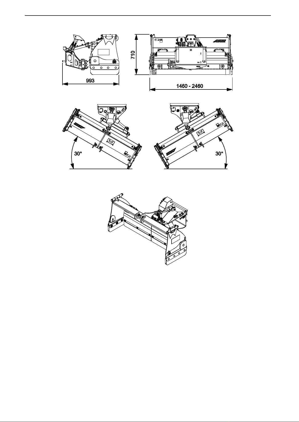
There are two hydraulic cylinders for stepless extending and retracting the straight blade sections of the plow.
This enables several different working widths and makes the snow plow very versatile at different work tasks
and areas. The plow is also equipped with hydraulic slewing, which makes it possible to tilt the plow towards
either side without interrupting work. An electro-hydraulic control valve on the snow plow makes it possible to
control the blade directly from the driver's seat. To operate all of these functions, the loader must be equipped
with Opticontrol®attachment control system.
The short overall design of the plow minimizes the torque force caused by the blade during use. The blade
edge is made of premium quality, wear resistant steel, and can be replaced if needed. A floating mounting
bracket allows vertical movement of the snow plow, as well as limited horizontal tilting for the best possible
ground surface following. To reduce the risk of a sudden stop if the blade hits an obstacle, there is a safety
bolt that will shear and allows the blade to tilt forward. Regardless of the shear bolt, the plow must be used
carefully and hitting obstacles at high speed must be avoided.
The Zoom snow plow is not designed for any other use than what is specified in this manual and it must not
be used for any other purposes than what it is intended for.
The attachment has been designed to require as little maintenance as possible. The operator can perform
regular maintenance tasks. All repair work can’t be performed by the operator, and demanding repair and
maintenance operations are to be left for professional technicians. All maintenance work must be done using
proper safety equipment. Spare parts must be identical with original specifications, which can be ensured by
using only original spare parts. A separate spare parts catalogue may be available, consult your Avant dealer.
Familiarise yourself with the manual's instructions regarding service and maintenance. Please contact your
AVANT dealer if you have additional questions about the operation or maintenance of the equipment, or if you
require spare parts or maintenance services.
Table 1 - Zoom snow plow - Compatibility with Avant loaders
Model
220
225
225LPG
313S
320S
420
423
520
R20
523
525LPG
R28
528
530
630
R35
635
640
735
745
750
755i
760i
850
860i
e5
e6
A425180 - - - - ••••(•)
It is recommended to use the attachment only with loaders marked with •in Table 1. When using with models
marked with (•), full performance may not be achieved. Additional counterweights may also be required. For
compatibility with a model not shown in table, contact your Avant dealer.

7 (30)
3. Safety instructions for using the snow plow
Please bear in mind that safety is the result of several factors. The loader-attachment combination is highly
powerful and improper or careless use or maintenance may cause serious personal injury or property
damage. Due to this, all operators must carefully familiarise themselves about correct use and the operator's
manuals of both the loader and the attachment before starting operation. Do not use the attachment if you
have not completely familiarised yourself with its operation and the related hazards.
DANGER
Misuse, careless use, or using an attachment that is in poor condition may
cause risk of serious injuries. Familiarise yourself with the controls
of the loader,
correct coupling procedure, and the correct way to operate the attachment at a safe
area. Study especially how to stop the equipment in a safe manner. Read all safety
precautions carefully.
Read all safety instructions carefully before handling the attachment
WARNING
When attaching an attachment to the loader, ensure that the locking pins of the
loader's quick attach plate are in the lower position and that they have locked
the attachment to the loader. Never lift or move an unlocked attachment.
This attachment is designed to be used by one operator at a time. Do not let others
near the danger area of the equipment when it is in use.
Always transport the attachment as low as possible to keep the centre of gravity low,
and keep the telescopic boom retracted during driving.
Risk of impact from sudden stop - Never plow at high speed unless you can be
sure that there are no obstacles at the working area.
The loader may stop
suddenly if it hits an obstacle. Remember that there may be hidd
en obstructions or
fragile surfaces under the snow. Always use seat belt and drive with caution.
Pay attention to the surroundings and any other persons and machines moving in the
vicinity. Pay attention to the contours of the terrain and other hazards,
such as
branches and trees that can reach to the driver's area, loose rocks, and slippery
surfaces.
Operate only at well lit areas. Make sure that all lights of the loader are in good
condition, clean, and adjusted correctly. Extra work lights are rec
ommended for the
loader when operating during dark. Mark any obstacle at the work area before
plowing to avoid collisions.
Risk of crushing under the attachment or the loader boom - Lower the
attachment firmly on the ground before leaving the driver’s seat.
Make sure that
the attachment is properly supported during any maintenance or inspections. Do not
leave the driver’s seat when the loader boom is lifted. Going under a raised
attachment or loader boom is dangerous, as the boom may lower due to loss of
stability, mechanical fault, or if another person operates the controls of the loader.
Make sure to use only an attachment that is in good condition. Do not modify the
attachment in any way that could affect its safety.
Shut down the loader and place the attachment to a safe position as shown in Safe
stopping procedure before any cleaning, maintenance, or adjustments.
Use the equipment only for its intended purpose. Other use may create unnecessary
safety risks, and the equipment may get damaged.

8 (30)
WARNING
Make sure that the loader is equipped with necessary safety components, and that
they are in working condition. Seat belt must be used. If there are specific hazards
related to the operating area, use appropriate safety equipment.
Also read the safety instructions and correct use of the loader from the operator's
manual of the loader.
DANGER
Risk of crushing -
Going under the loader boom or an
attachment can cause serious injury or death.
Never go
under the loader boom and prevent others from ge
tting near
lifted boom or attachment. Going under a raised attachment
or loader boom is dangerous, as the boom may lower due to
loss of stability, mechanical fault or when other person
operates the controls of the loader. Lower the attachment
firmly on the
ground to a safe position before leaving the
driver’s seat.
Keep in mind that the loader boom can be lowered or tilted
even if the engine has been shut down (crushing hazard).
The loader is not intended to be left to keep a load elevated
for longer period
s. Always lower the attachment to a safe
position before leaving the driver's seat.
Observe the local regulations concerning the use of the equipment on public roads. The
loader may need to be registered for road use. Contact your local Avant dea
ler or local
authorities for more information.
3.1 Personal protective equipment
Remember to wear proper personal protective equipment:
The noise level at the driver's seat may exceed 85 dB(A) depending on loader
model and operating cycle. Extended expo
sure to loud noise can cause
hearing impairment. Wear hearing protection while working with the loader.
Wear protective gloves.
Wear safety boots whenever working with the loader.
Wear safety glasses e.g. when handling hydraulic components.
. ..

9 (30)
3.2 Safe shutdown procedure
Safe stopping of the attachment, before going near the attachment:
WARNING
Always stop the attachment following safe stopping procedure before leaving
the driver's seat. Safe stopping procedure prevents all unintentional move
ments of
the attachment. Note that the loader boom can move down even if the engine of the
loader is turned off. Safe stopping procedure:
Lower the boom and the attachment on the ground.
Shut down the loader engine and lock the parking brake.
Release resid
ual pressure from the hydraulic system; move all hydraulic control
levers to their extreme positions a couple of times.
Prevent starting of the machine, remove ignition key.

10 (30)
4. Technical specifications
Table 2 - Zoom snow plow - Specifications
Product number A425180
Working width: 1350 - 2350 mm
Total width: 1460 - 2460 mm
Length: 993 mm
Weight: 535 kg
Slewing angle: 30° towards either side
Recommended hydraulic oil flow: 10-20 l/min
Maximum input of hydraulic energy: 30 l/min
22,5 MPa (225 Bar)
Other dimensions: See page 2
Compatible AVANT loader models: See table 1 on page
4.1 Safety labels and main components of the attachment
Listed below are the labels and markings on the attachment. They must be visible and readable on the
equipment. Replace any unclear or missing label. New labels are available via your retailer or contact
information provided on the cover.
WARNING
Make sure all warning decals are readable.
The warning labels contain important
safety information an
d they help to identify and remember the hazards related to the
equipment. Replace damaged or missing warning labels with new ones.
. ..
Attachment identification plate
A425702
A46771 A46772 A46803
. ..
To apply a new label: Clean the surface thoroughly to remove all grease. Allow it to dry completely. Peel off
the protective film of the label and press firmly to apply. Take care not to touch the glue of the label.

11 (30)
Table 3 - Decal locations and warning messages
Decal Warning message
1 A46771 Misuse hazard -
Read instructions before
use.
2 A46772 Crushing hazard -
Do not go under a
raised attachment; stay away from raised
equipment.
3
A46803
Pinching and cutting hazard, keep clear
of moving parts, do not leave the
equipm
ent running. Operate the
attachment only from the driver’s seat.
4
A425702
Attachment identification plate
. ..
Table 4 - Zoom snow plow - Main components
1
Quick coupling plate with Avant quick coupling
brackets
2 Multi connector holder
3 Extending section (right side)
4 Side plates, in lower position (2 pcs)
5 Slewing cylinder (side tilt)
6 Electro-hydraulic control valve
7 Extension cylinders for blade sections (2 pcs)
8 Top link and safety bolt
9 Blade edge

12 (30)
5. Assembling the attachment
Attaching the attachment to the loader is quick and easy, but it must be done carefully. The attachment is
mounted to the loader boom by using the quick coupling plate on the loader boom and the counterpart on the
attachment.
If the attachment is not locked to the loader, it may fall from the loader and cause a hazardous situation.
Never drive with the loader and never lift the loader boom if the attachment has not been fully locked. To
prevent hazardous situations, always follow the coupling procedure shown below. Also remember the safety
instructions shown in this manual.
WARNING
Crushing risk - Make sure that an unlocked attachment will not move or fall over.
Do not stay in the area between the attachment and the loader. Mount the attachme
nt
only on level surface.
Never move or lift an attachment that has not been locked.
Avant quick coupling system:
Step 1:
Lift the locking pins of the quick coupling plate of the loader up, and turn them
backwards into the slot, so that they are locked in the upper position.
If your loader is equipped with a hydraulic attachment locking system, see
additional instructions about the use of the locking system from the operator's
manual of the loader.
Make sure that the hydraulic hoses are positioned so
that they will not get in
between the coupling plate of the loader and the attachment, and that they will
not get squeezed or chafed against sharp edges.
Step 2:
Turn the quick coupling plate hydraulically to an obliquely forward position.
Drive the
loader onto the attachment. If your loader is equipped with a
telescopic boom, you can use it to reach to the coupling brackets of the
attachment.
Align the upper pins of the loader’s quick coupling plate so that they are under
the corresponding brackets of the attachment.
Step 3:
Lift the boom slightly –
pull the boom control lever backward to lift the
attachment just off the ground.
Turn the boom control lever left to turn the bottom section of the quick coupling
plate of the loader onto the attachment.
Lock the locking pins manually or lock the hydraulic locking.
Always check the locking of both locking pins.

13 (30)
WARNING
Risk of crushing - Avoid tipping over the attachment.
Excessive tilting or lifting of an
unlocked attachment increases the ris
k of tipping the attachment over. Do not use the
automatic locking of the locking pins when the attachment is lifted more than one meter
from the ground. If the locking pins do not return to the normal position when tilting, do
not tilt or raise the attach
ment any more. Lower the attachment on the ground and
secure the locking manually.
WARNING
Risk of falling objects -
Prevent dropping of
attachment.
An attachment that has not been completely locked to the
loader may fall on the boom or towards the
operator, or
fall under the loader during driving, causing loss of
control of the loader. Never move or lift an attachment
that has not been locked. Before moving or lifting the
attachment, make sure that the locking pins are in the
lower position and come
through the fasteners on the
attachment on both sides.
WARNING
Make sure the loader is compatible with the attachment.
Stability of the loader,
possible overload of the attachment, and compatibility of loader control systems must be
ensured in
addition to mechanical compatibility of the attachment. If you use the
attachment with a loader that is not fit to be used with the attachment model you have,
risks include tipping over, damage to attachment due to overload, and risks related to
uncontroll
ed motion of attachment and its parts. If your loader is not listed in Table 1 on
page , ask your Avant dealer before using this attachment.
5.1 Connecting and disconnecting hydraulic hoses
On Avant loaders the hydraulic hoses are connected using the multi connector system. If you have an older
model Avant 300-700 series loader with the conventional quick couplers, and you want to change to the multi
connector system, contact your Avant dealer or service point for instructions or installation services.
WARNING
Risk of movement of the attachment and ejection of hydraulic oil -
Never connect
or disconnect quick couplings or other hydraulic components while the control
lever of the auxiliary hydraulics control lever is locked on or if the system is
pressurized.
Connecting or disconnecting the hydraulic couplings while the system is
pressurized may lead to unintended movements of the attachment, or ejection of high-
pressure fluid, which can cause serious injuries or burns. Follow safe stopping procedure
before disconnecting hydraulics.

14 (30)
Keep all fittings as clean as possible; use the protective caps on both the attachment and
the loader. Dirt, ice, etc. may make using the fittings significantly more difficult. Never
leave the hoses hanging on the ground
; place the couplings onto the holder on the
attachment.
Connecting the multiconnector system:
1.
Align the pins of the attachment connector with corresponding
holes of the loader connector. The multiconnector will not connect
if the attachment connector is upside down.
2.
Connect and lock the multiconnector by turning the lever towards
the loader.
The lever should move easily all the way to its locking position. If the lever does not slide smoothly, check the
alignment and position of the connector and clean the connectors. Also shut down the loader and release the
residual hydraulic pressure.
To disconnect the multiconnector system:
Before disconnecting put the attachment down on a solid and even
surface.
1. Switch off the auxiliary hydraulics of the loader.
2.
While pushing unlock button, turn the lever to disconnect the
connector.
3.
After ending operation put the multiconnector on its holder on the
attachment.
Disconnecting hydraulic hoses:
Before disconnecting the fittings, lower the attachment to safe position on solid and level surface. Turn the
control lever of the auxiliary hydraulics to its neutral position.
When uncoupling the attachment, always disconnect the hydraulic couplings before
unlocking the quick coupling plate, to prevent hose dam
age and any oil spills. Reinstall
the protective caps on the fittings to prevent impurities from entering the hydraulic
system.
Releasing residual hydraulic pressure:
In case residual pressure is left in the hydraulic system of the attachment, it is often possible to disconnect the
hydraulic couplings, but it may be difficult to connect them the next time. If the fittings will not connect, the
residual pressure must be released by turning the auxiliary hydraulics control lever of the loader, when the
engine is turned off. To make sure that there will not be residual pressure in the hydraulic system of the
attachment, shut down the loader engine and move the auxiliary hydraulics control lever of the loader back
and forth before disconnecting the couplings.

15 (30)
5.1.1 Electric connection
Electric functions of the attachment:
The plow has multiple functions, which makes it necessary to have the Opticontrol® system installed on the
loader. See page 20 for more information.
The loader must be equipped with the Opticontrol®
system in order to control all functions
of the attachment.
. ..
5.1.1.1 To connect the electric harness of the attachment to the loader
Starting from year 2016, there is an integrated electric plug in the multiconnector of all attachments that have
electric functions.
1. If your loader is
equipped with the Opticontrol®system, and
the loader is manufactured in 2016 or later:
The electric socket is integrated in the
multiconnector. The electric harness of the
attachment is conn
ected when the multiconnector
is coupled.
Clean both multiconnectors before connecting the
multiconnector.
Opticontrol®, loader manufactured in 2016 or
later
2. If your loader is
equipped with the attachment control switch
pack, and
the loader is manufactured in 2015 or before:
There is an electric socket near the multiconnector
of the loader. Connect the electric plug of the
attachment to the socket of the loader.
Attachment control switch pack, loader
manufactured in 2015 or before

16 (30)
If your loader is not equipped with the Opticontrol®:
All functions of the plow can't be used without the Opticontrol®system on the loader.
Make sure that electric cables will not get stuck, squeezed, or stretched when the
equipment moves.
With the help of the Opticontrol®
system available for the loader, the attachment control
switches are easily accessible at the end of the boom control lever.
More information about the power outlet of the loader can be found in the operator’s
manual of the loader.
. ..
Retrofit kit:
The functionality of the Opticontrol® system is available as retrofit kit A437338. See separate instructions
about retrofitting of the wire harness from the instructions of the retrofit kit.

17 (30)
6. Operating the attachment
Check the attachment and the operating environment once more before starting to work, and that all obstacles
have been removed from the operating area. Quick inspection of the equipment and the operating area before
use are parts of ensuring safety and the best performance of the equipment.
Practise the use of the attachment and its controls in an open and safe area. If you are unfamiliar with the
loader in use, it is recommended to practise its use without any attachments.
WARNING
Collision risk - Check the operating area before using the equipment. If the plow hits
an obstacle the loader can stop suddenly and unexpectedly, causing injuries from impact
to head and body, regardless of the blade spring release system or other safety systems.
Drive slowly and pay attention to operating area at all times.
Make sure that there are no hidden obstacles under the snow, for example.
Do not let bystanders stay near the machine. Stop the attachment if others get
closer than 5 metres from the attachment.
Mark visibly any potential ob
structions beforehand as far as practical so that
collisions can be avoided.
Operate equipment only at well lit areas or make sure the loader is equipped with
sufficient lights.
The spring loaded blade sections improve safety only when driving forward -
when reversing, drive extremely slow.
Always wear seat belt.
WARNING
Risk of crushing -
Never allow anyone to get under a
lifted attachment or loader boom.
Keep in mind that the
loader boom can be lowered or tilted even if the engine has
been shut dow
n (crushing hazard). The loader is not intended
to be left to keep a load elevated for longer periods. Always
lower the attachment to a safe position before leaving the
driver's seat.
WARNING
Risk of collisions - Ensure good visibility. Never lift
this attachment to a height where
visibility from the driver's position is obstructed. Ensure unobstructed visibility to all
directions. Keep all windows clean and free of dirt, ice, snow etc.
.

18 (30)
6.1 Checks before use
Check that all obstacles, including any possibly hidden ones, have been removed from the working
area or marked visibly before operation.
Ensure that bystanders are at a safe distance when operating the equipment. Do not let anyone to
enter danger area of the boom or to stay directly in front of the loader. Also make sure that it is safe to
reverse with the loader. Never assume that bystanders will remain where you last saw them;
especially children are often attracted to the moving equipment.
Check the general condition of the attachment and the loader, and check for possible hydraulic oil
leaks. Do the daily checks of the loader, see the operator's manual of the loader. The attachment must
not be used, if there is a fault in the hydraulic system of the loader or the attachment. Refer to Chapter
7 for maintenance instructions.
Operate the attachment and the controls of the loader only when seated on the driver’s seat. Ensure
that the loader and the attachment are used in a safe manner and as intended. Do not allow children
to operate the equipment.
Remember correct working methods and avoid leaving the driver’s seat unnecessarily.
WARNING
Risk of injuries related to sudden stop -
Drive slow and always stay alert for
possible obstacles. For the safety of the operator, the blade is
equipped with safety
mechanisms to reduce the risk of sudden stopping of the machine and the possibility of
injuries that could follow. However, the existence of the safety features will not replace
operator's responsibility. Careful and cautious operatin
g are essential for safety. Any
safety feature by itself will not guarantee safe operating of the plow. The performance of
the safety features may be hindered in certain conditions, such as packed snow or ice, or
when reversing with the loader.
6.2 Operator qualification
Anyone who intends to use the attachment must:
Know the intended use of the attachment.
Know how to use the loader safely in different operating conditions.
Read and always follow the instructions concerning the use of the attachment in this operator's
manual.
Have this manual and the operator's manual of the loader available.
Ensure that the loader and the attachment are used in a safe manner and as intended.
Never allow children to operate the equipment.
Never operate the loader or attachments while under the influence of alcohol, drugs, medication that
may impair judgement or cause drowsiness, or if not otherwise medically fit to operate the equipment.
Complete any possible mandatory training required by the employer before use.
.

19 (30)
6.3 Operating position
For the best performance of the plow, set the attachment to correct operating position:
1.
Place the plow on the ground surface so
that the plow (the quick coupling plate of
the loader) is in upright position.
2. When the plow is lowered on the gro
und,
lower the boom slightly more, so that the
floating system of the attachment allows
the blade to move. See page 22
for
instructions about the floating system.
3.
As a general rule, the attachment should
be adjusted so that the quic
k coupling plate
of the loader is in upright position.
Depending on specific circumstances at
your work area, you may try to tilt the blade
a little to front or back. The vertical position
of the attachment will affect the outcome
and accuracy of plowing.
The plow should not be pressed hard against the ground as this will affect the handling of the loader, as the
front wheels of the loader begin to lift from ground surface. Avoid pressing the plow hard against the ground to
prevent excessive wear of the plow.

20 (30)
6.4 Controlling the plow - different functions of the plow
The different functions of the plow are controlled with the Opticontrol®system of the loader. The Opticontrol®
mode is switched on with a separate selection switch on the loader. When pushing the attachment control
switches installed to the joystick of the loader, Opticontrol®will activate the auxiliary hydraulics of the loader
simultaneously as necessary.
The loader must be equipped with the Opticontrol®system in order to control all fu
nctions
of the attachment.
. ..
Basic principle of using the plow:
1 Switch on the Opticontrol®
mode with the separate selection switch on the loader. See the
adjacent figure, and the operator's manual of the loader.
2 Control the desired function w
ith the switches of the Opticontrol® system or use the auxiliary
hydraulics control lever on the loader to control the selected function (or use buttons of
electric joystick).
Operating the plow
Switches of the Opticontrol® system
1. ON/OFF switch:
Switch to ON (I) to select both side wings
0 to select the slewing function of the plow
Use the red and blue pushbuttons to control the selected functions.
2. 2-way control switch:
Control the left side wing directly, Opticontrol activates auxiliary
hydraulics when switch is pressed
3. 2-way control switch:
Right side wing
When the loader is equipped with the attachment control switch pack but not the
Opticontrol® system, the side wings can be selected but not controlled with switches 2
and 3. For controll
ing the wings it is necessary to use the auxiliary hydraulics control lever
or the red and blue pushbuttons, in addition to the switches. It is not intended to control
the attachment this way, instead the full opticontrol system must be used.
. ..
Table of contents
Other Avantco Snow Blower manuals