SOC Robotics MM130 Product manual
MM130 Technical Reference Manual
© Copyright 2010. SOC Robotics, Inc. 1 Manual Revision 1.01
June 2010
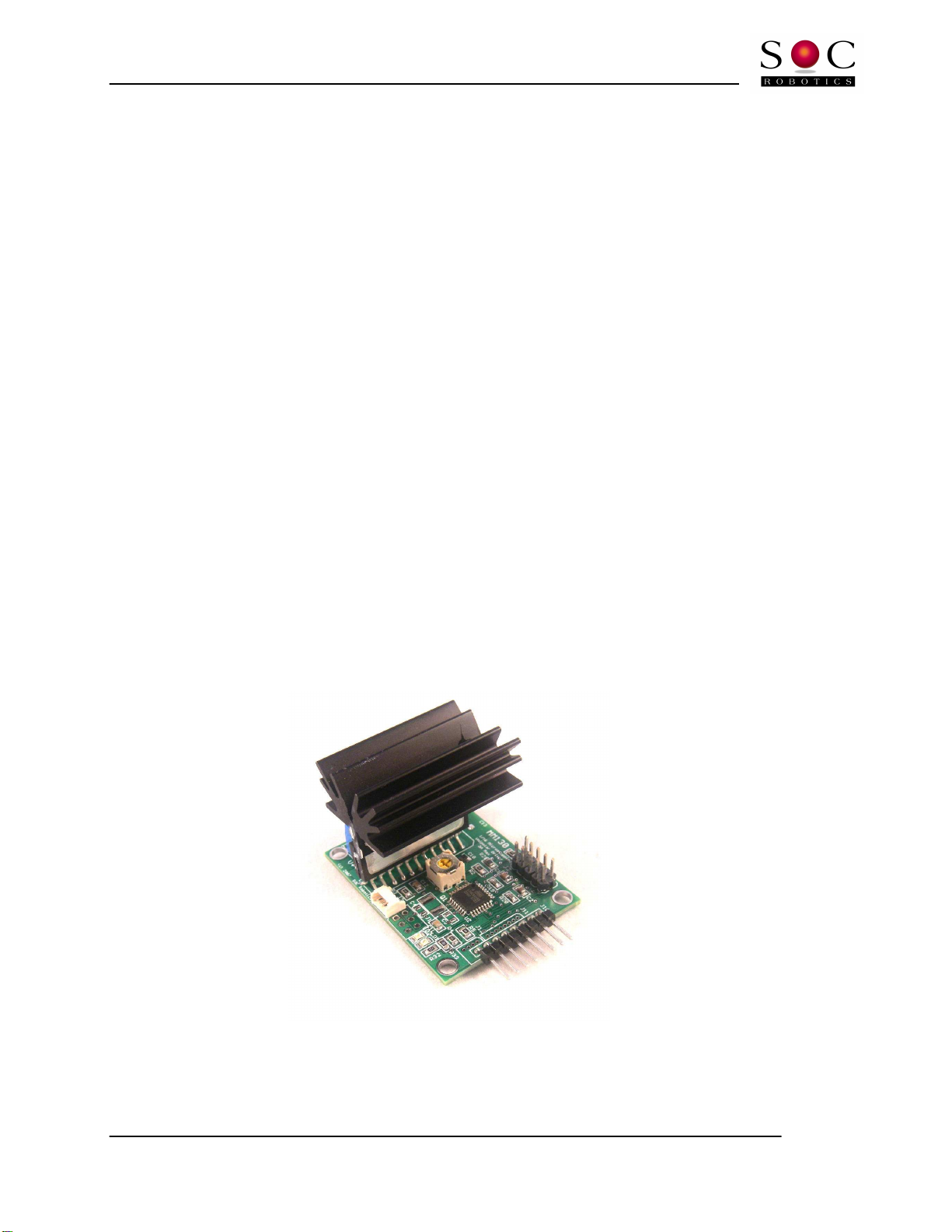
MM130 Single Axis Stepper Motor Driver
1/16
th
Microstepping 3A Unipolar Driver
Technical Reference Manual
PCB Rev 1.1
Motor Control So tware Version 1.00
www.soc-robotics.inc

MM130 Technical Reference Manual
© Copyright 2010. SOC Robotics, Inc. 2 Manual Revision 1.01
June 2010
Warranty Statement
SOC Robotics warrants that the Product delivered hereunder shall con orm to the applicable SOC Robotics Data Sheet or mutually
agreed upon speci ications and shall be ree rom de ects in material and workmanship under normal use and service or a period o
30 days rom the applicable date o invoice. Products that are “samples”, “design veri ication units”, and/or “prototypes” are sold
“AS IS,” “WITH ALL FAULTS,” and without a warranty. I , during such warranty period, (i) SOC Robotics is noti ied promptly in
writing upon discovery o any de ect in the goods, including a detailed description o such de ect; (ii) such goods are returned to
SOC Robotics, DDP SOC Robotics acility accompanied by SOC Robotics Returned Material Authorization orm; and (iii) SOC
Robotics examination o such goods discloses to SOC Robotics satis action that such goods are de ective and such de ects are not
caused by accident, abuse, misuse, neglect, alteration, improper installation, repair, improper testing, or use contrary to any
instructions issued by SOC Robotics. SOC Robotics shall (at its sole option) either repair, replace, or credit Buyer the purchase price
o such goods. No goods may be returned to SOC Robotics without SOC Robotics Returned Material Authorization orm. Prior to
any return o goods by Buyer pursuant to this Section, Buyer shall a ord SOC Robotics the opportunity to inspect such goods at
Buyer’s location, and any such goods so inspected shall not be returned to SOC Robotics without its prior written consent. SOC
Robotics shall return any goods repaired or replaced under this warranty to Buyer transportation prepaid, and reimburse Buyer or
the transportation charges paid by Buyer or such goods. The per ormance o this warranty does not extend the warranty period or
any goods beyond that period applicable to the goods originally delivered.
THE FOREGOING WARRANTY CONSTITUTES SOC ROBOTICS EXCLUSIVE LIABILITY AND THE EXCLUSIVE REMEDY
OF BUYER FOR ANY BREACH OF ANY WARRANTY OR OTHER NONCONFORMITY OF THE GOODS COVERED BY
THIS AGREEMENT. THIS WARRANTY IS EXCLUSIVE AND IN LIEU OF ALL OTHER WARRANTIES. SOC ROBOTICS
MAKES NO OTHER WARRANTIES EXPRESS IMPLIED OR STATUTORY INCLUDING WITHOUT LIMITATION ANY
WARRANTIES OF MERCHANTABILITY OR FITNESS FOR A PARTICULAR PURPOSE. THE SOLE AND EXCLUSIVE
REMEDY FOR ANY BREACH OF THIS WARRANTY SHALL BE AS EXPRESSLY PROVIDED HEREIN.
Limitation on Liability
Notwithstanding anything to the contrary contained herein, SOC Robotics shall not, under any circumstances, be liable to Buyer or
any third parties or consequential, incidental, indirect, exemplary, special, or other damages. SOC Robotics total liability shall not
exceed the total amount paid by Buyer or SOC Robotics hereunder. SOC Robotics shall not under any circumstances be liable or
excess costs o re-procurement.
© Copyright 2010. SOC Robotics, Inc. All rights reserved.
SOC Robotics, Inc. makes no warranty or the use o its products, other than those expressly contained in the Company’s standard
warranty which is detailed in SOC Robotics Terms and Conditions located on the Company’s web site. The Company assumes no
responsibility or any errors which may appear in this document, reserves the right to change devices or speci ications detailed
herein at any time without notice, and does not make any commitment to update the in ormation contained herein. No licenses to
patents or other intellectual property o SOC Robotics are granted by the Company in connection with the sale o SOC Robotics
products, expressly or by implication. SOC Robotics products are not authorized or use as critical components in li e support
devices or systems.
Pentium is a registered trademark of Intel Corporation.
Windows, Windows NT and Windows XP are registered trademarks of Microsoft Corporation.
Marks bearing
®
and/or
™
are trademarks of SOC Robotics, Inc.
Terms and product names in this document may be trademarks of others.
1935A–08/00/5M

MM130 Technical Reference Manual
© Copyright 2010. SOC Robotics, Inc. 3 Manual Revision 1.01
June 2010
Table of Contents
Warranty Statement
………………………………………………………………………2
1.0
Introduction
………………………………………………………………………….4
2.0 Detailed Description
………………………………………………………...……9
2.1 Introduction………………………………………….………………………………..…..…9
2.2 Processor...…………………………………….………..……………………………..……9
2.3 TWI Port...…………………………………………………………………….….……..…..10
2.4 Auxiliary IO Port...……………………………..……………………………..………..…..10
2.5 ISP Programming Port...………………………………………………………..……..… 10
2.6 Molex Connector………………………..…………………………………………….……11
2.7 Related Peripherals……………………..……………………………………..…..…...…11
2.8 Applications………………………………..……………………………………………….12
3.0 Hardware Expansion Port Summary
…………………………….………..13
3.1 Introduction………………………………………………………………………….…...…13
3.2 Motor Control Port……..………..……………….…………………….…………….….…14
3.3 Auxiliary IO Port ………...…………………………………………………………………14
3.4 TWI I2C Expansion Port .……………..……………………………………………..……15
3.5 ISP Programming Port……………………….……………………………………………15
4.0 Software Operation
…………………………………………….……….………..16
4.1 Theory of Operation…………………………...…...……………………………….…..…16
4.2 Auxiliary IO……..……………………….…………..………………….…………….….…16
4.3 Step Drive Connector ………...……..……………………………………………………16
4.4 Driver Commands.…………………….……..……………………….……………..….…17
4.5 MM130 Command Overview .……………..………………………………………..……18
4.6 Detailed Command Description…………………..………………………………………21
5.0 Electrical and Mechanical Description
…………………………..….……30
5.1 Component Layout…………………………………………………………………...……30
5.2 Electrical Specifications……………………………………………………………...……30
5.3 Mechanical Dimensions ……………………………………………….…………….……30
6.0 Circuit Schematics
………………………………………………………....……31
MM130 Technical Reference Manual
© Copyright 2010. SOC Robotics, Inc. 4 Manual Revision 1.01
June 2010
1.0 Introduction
Features:
•
Unipolar 3A Stepper Motor Driver
•
Maximum motor drive voltage 44V
•
Full, half, quarter, eighth and sixteenth microstepping
• Maximum 3 A per phase
• Backlash compensation built-in
• On board 20MHz RISC AVR processor – Atmega168
• SPI Port
• TWI I2C Communication Protocol Built-in
•
16K Internal Program Flash
•
512 Internal EEPROM
•
1K Internal SRAM
•
ISP Programming Port
•
GNU C Compiler, Third Party Commercial C Compiler
•
Extremely small form factor (2.10x1.54 in)
• 5VDC @ 12ma Power input for logic
• Motor drive input 10-44VDC at 3A
Hardware
The MM130 is a 1/16
th
Microstepping Unipolar 3A per phase stepper motor driver that converts step and
direction signals to the appropriate high voltage stepper motor drive signals. The board is designed to
operate at 5VDC. Motor voltage can vary rom 10-44VDC. The motor drive chip is controlled by a
dedicated onboard 8 bit RISC processor (Atmega168) that provides various expansion and enhancement
eatures. Applications can communicate with the board via an I2C inter ace or using encoded commands
on the step and direction inputs. A Limit switch input can be monitored and acted on but are turned o
by de ault. An EStop input is can also be monitored to stop step operation.
The MM130 consumes about 12ma in active state not including motor drive current.
Motor Control Software
The MM130 is shipped with a sophisticated so tware application burned into the on board Atmega168
processor that controls the SLA7078 driver chip, monitors step/direction inputs, limit switch state,
encoded commands on the step/direction input lines and commands received on the I2C port. The
MM130 can operate as a single axis G Code processing system by acting on commands sent to it via the
I2C or Step/Direction input lines. See the section on so tware operation or a ull description o the
complete command structure. Free application GstepPP.exe can send coded commands to the MM130 on
the Step/Direction lines.
The control program in the MM130 processor can be re-Flashed using programming cable Part No. MCM-
8 and the appropriate host so tware MK4Prog.exe.
The MM130 can be custom programmed in C using either a GNU C Compiler, AVR Studio V4.13 or
higher with GNU C integrated with the IDE or a third party IDE such as ICCAVR rom ImageCra t.
MM130 Technical Reference Manual
© Copyright 2010. SOC Robotics, Inc. 5 Manual Revision 1.01
June 2010
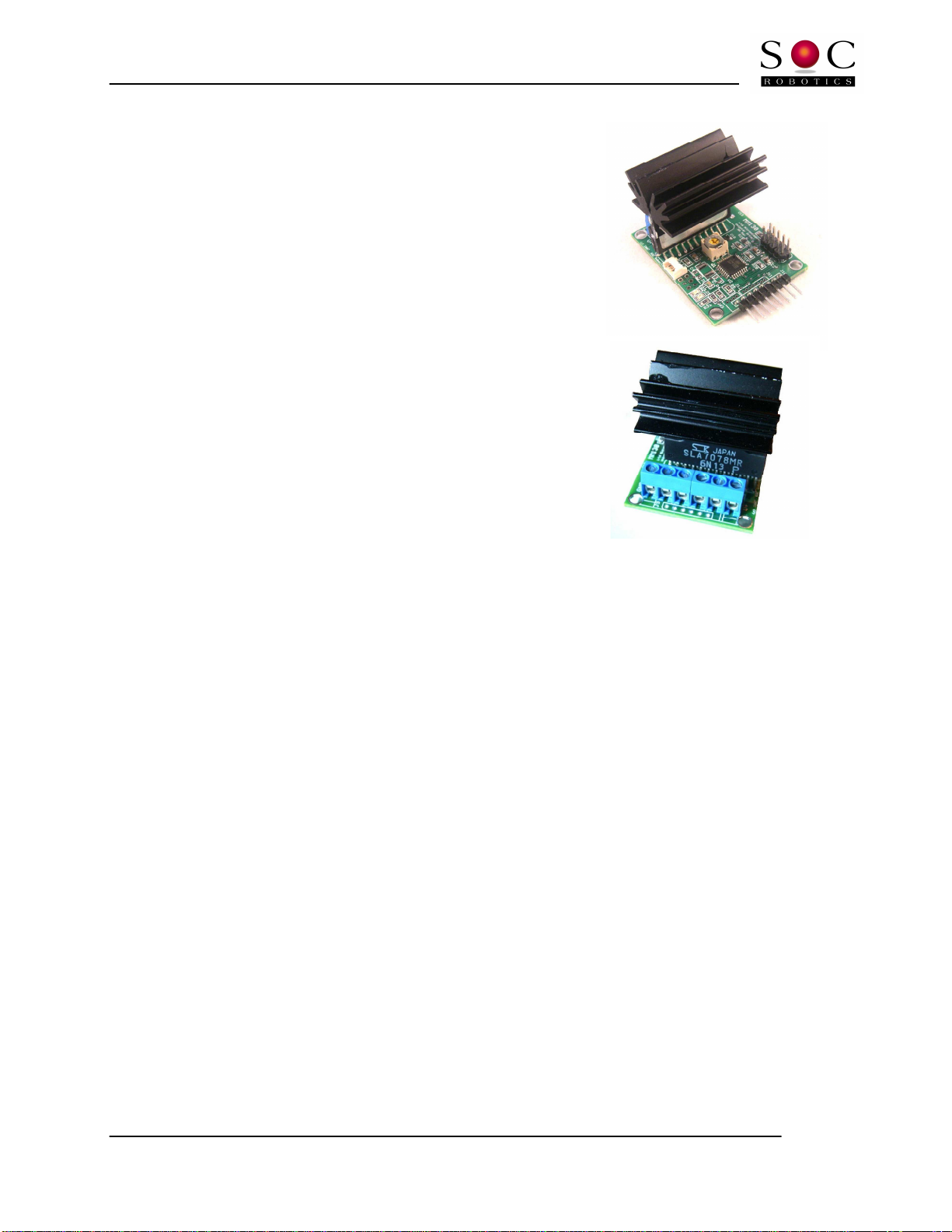
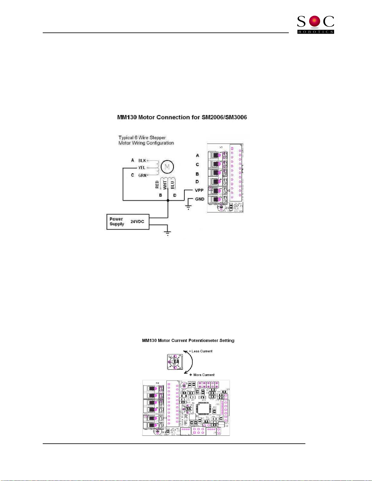
Stepper Motor Connection
Motor Drive voltage should be between 10-44VDC. A potentiometer sets average current and should be
adjusted while the board is running. A heat sink provides radiant cooling so orced air cooling is not
required in most applications. Under extreme operating conditions orced air cooling should be used.
The diagram below shows stepper motor connections or the SM2006 and SM3006 stepper motors – wire
color or other stepper motors may vary although most coil phase diagrams are similar. It is a good idea
to wire a use between the motor power supply and the MM130. Try not to turn motor power on i the
logic side o the MM130 is not turned on. I the motor will not turn then check your wiring.
Adjusting Motor Drive Current
The MM130 has a single potentiometer or setting motor drive current. Turning the potentiometer
clockwise increases current while turning the potentiometer counterclockwise decreases current. By
de ault the potentiometer is set in the middle o the range at the actory – this delivers 1.5amps – ully
clockwise delivers the maximum rating o the SLA7078 which is 3.0amps. The potentiometer should be
set to deliver the rated current the motor requires. It is possible to set the potentiometer in such a way
that the control chip delivers too much current to the motor resulting in motor overheating. I the motor
missteps at high step rates then your motor maybe undersized or your application and can not develop
enough torque – in this case use a bigger motor. Increasing drive voltage will increase maximum step
rate. The maximum step rate o a stepper motor is determined by drive voltage, coil inductance and step
mode. Changing step mode rom hal step to quarter step can reduce e ective drive torque by 40%.
MM130 Technical Reference Manual
© Copyright 2010. SOC Robotics, Inc. 6 Manual Revision 1.01
June 2010
MM130 Controllers
Although the MM130 can operate standalone it usually requires a controller to send step and direction
input signals to it. SOC Robotics has several controllers compatible with the MM130 - MC-USB, MK1,
MK4, MK14, MK54 and MK200. Each controller supports increasing levels o sophistication and control
lexibility. The MK1 is a simple breakout board that allows three MM130’s to be attached and controlled.
The MK4 is a our axis breakout board with our auxiliary output ports, our limit switch inputs and one
Estop input. The MK14 is a special version o the MK4 with a USB 2.0 inter ace. The MK54 is a high
per ormance G Code processor with 10/100BaseT, CAN and USB 2.0. The MK200 is an ultra high
per ormance G Code processor with onboard vision processing. For more in ormation on our line o
controllers and to help determine which one is best or your application go to our web site or contact the
irm.
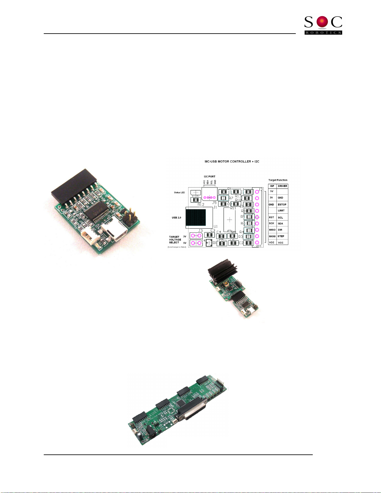
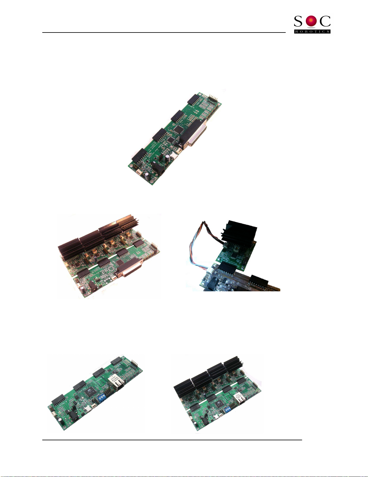
With the MC-USB stepper motors can be controlled via a host PC USB port.
The MC-USB is a USB 2.0 based controller
that generates the step/direction signals to
control the MM130. An I2C communications
bus allows a host PC to communicate with the
MM130 in real time allowing step mode changes,
limit switch detection and aux IO monitoring
and control.
MM130 with MC-USB Controller
The MK4 is an optional parallel port controller with connectors or our MM130 drivers. The MK4 has
our aux open collector outputs and ive limit switch inputs all set/read via the parallel port. The MK4 is
an excellent choice to attach up to our MM130’s to a PC’s parallel port and be controlled using Mach3.
MK4 Controller
MM130 Technical Reference Manual
© Copyright 2010. SOC Robotics, Inc. 7 Manual Revision 1.01
June 2010
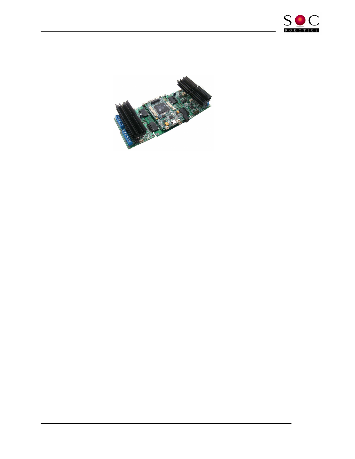
The MK14 is a USB 2.0 version o the MK4 with an onboard processor that accepts up to our MM130
drivers. The MK14 has our aux open collector outputs and ive limit switch inputs all read via the
parallel port. The onboard processor (AT91USB162) accepts step commands via USB and allows the host
PC to communicate with the individual MM130 drivers and send high commands directly to each driver.
In this case the parallel port inter ace can be bypassed and commands sent directly to each MM130
processor using a standard serial communications protocol.
MK14 Controller
MK14 with 3 MM130’s and MM133 MM130 Programming Cable
The MK54 is a high end G Code processor with onboard ARM7 processor running 55MHz. The ARM7
processor executes G Code directly eliminating the need or a PC based G Code processor. The MK54 is
capable o receiving commands via a USB 2.0 inter ace, 10/100BaseT Ethernet or CAN.
MM130 Technical Reference Manual
© Copyright 2010. SOC Robotics, Inc. 8 Manual Revision 1.01
June 2010
The MK200 is a high end DSP based G Code processing plat orm with built-in vision processing that is
capable o driving the MM130’s at their maximum rate o 80,000 microsteps/second. The MK200 is
intended or high end applications that require extremely ast stepper motor operation and/or real time
vision processing.
The correct controller or your application depends on many parameters. I you require help in choosing
a controller or need additional in ormation please contact the company.
MM130 Technical Reference Manual
© Copyright 2010. SOC Robotics, Inc. 9 Manual Revision 1.01
June 2010
2.0 MM130
Detailed Description
2.1 Introduction
The MM130 is a compact single axis stepper motor microstepping driver with a dedicated onboard
processor. The processor responds to step/direction signals on the primary control input port, receives
and interprets commands received on the I2C inter ace or encoded on the step/direction signal lines and
processes sensor data received on the auxiliary IO port.
2.2 Processor
The MM130 has an 8bit RISC AVR processor (ATmega168) running at 20MHz. Note that the Atmega168
requires 5VDC to run at 20MHz. The program running in the Atmega168 monitors the step/direction
input lines and drives the SLA7078 microstepping driver chip. Commands supported by the processor
irmware is described in the so tware operation section o this manual.
Figure 2
-1. Primary Components on top and bottom sides of PCB.
MM130 Technical Reference Manual
© Copyright 2010. SOC Robotics, Inc. 10 Manual Revision 1.01
June 2010
Figure 2
-3. MM130 Auxiliary IO port pin assignments.
Figure 2
-2. MM130 I2C port pin assignments.
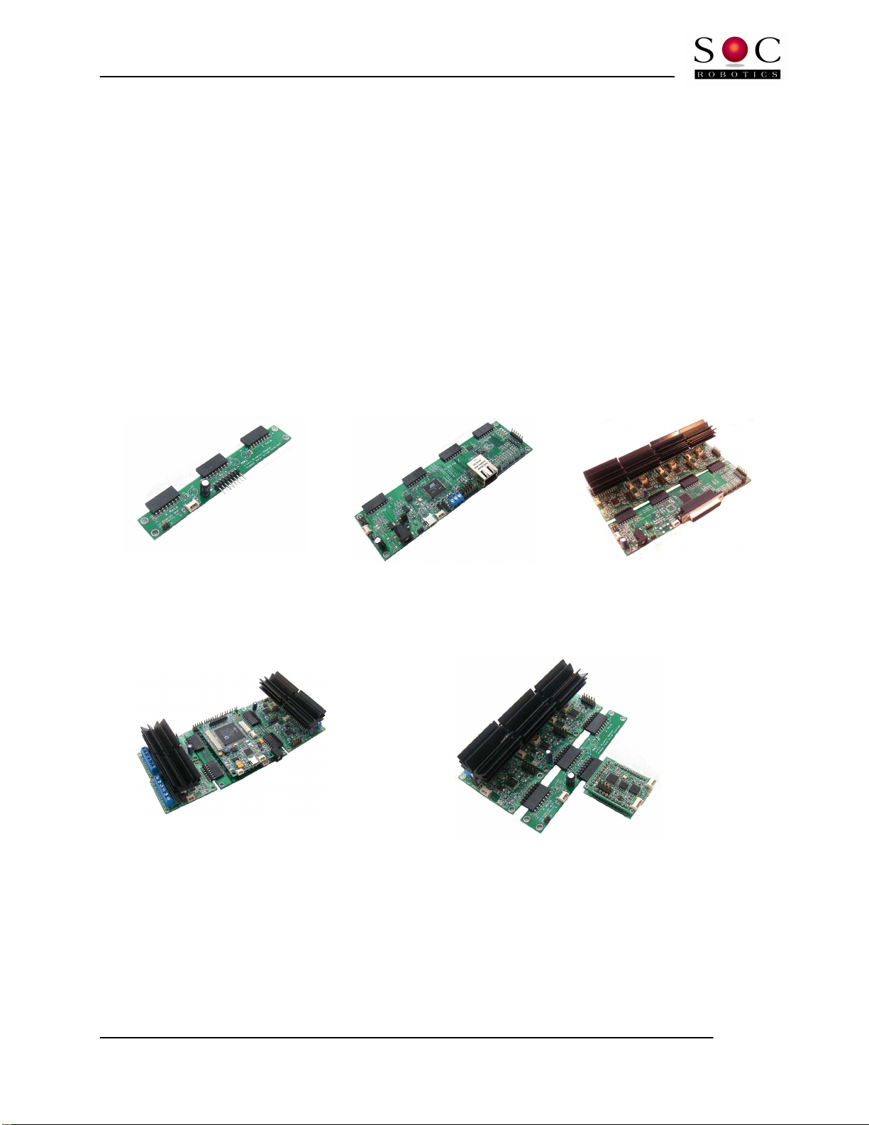
2.3 TWI Port
The MM130 has a TWI I2C port or communicating with smart peripherals or other I2C peripherals. The
TWI port uses a 4 pin Molex connector with power and ground so the MM130 can power other
peripherals or be powered itsel via this connector. De ault I2C address is 0x20. The Molex connector is
not installed but can be optionally added to the board.
2.4 Auxiliary IO Port
The MM130 has an auxiliary IO port. The auxiliary IO port supports two analog input line and several
digital IO lines. The current so tware does not process data on this port.
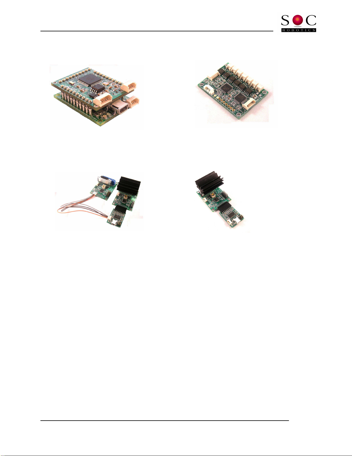
2.5 ISP Programming Port
The MM130 has two ISP programming ports – a 4 pin Molex connector and a 6 pin header. The MM130’s
Flash can be programmed by attaching a 4 line cable rom the MK4 programming port to the Molex
connector. The 6 pin header is not installed but can be added as an optional component. Alternatively
the MM130 lash can be programmed using a separately supplied ISP10 Programming Adapter and
ISP610 adapter.
Figure 2
-4. ISP610 ISP Adapter and correct attachment to the MM130 .
MM130 Technical Reference Manual
© Copyright 2010. SOC Robotics, Inc. 11 Manual Revision 1.01
June 2010
2.6 Molex Connectors
The MM130 uses two small Molex picoBlade 4 pin connectors with 1.25mm pin spacing (4 pin Molex Part
No. 53048-0410 - Digikey Part No. WM1744-ND). These connectors mate with emale Molex 4 housing
connectors (4 pin housing Molex Part No. 51021-0400 - Digikey Part No. WM1722-ND).
The housing connectors crimp terminal accepts 26-28AWGwire (Molex Part No. 50079-8000 - Digikey
Part No. WM1722-ND – Crimp tool 63811-0300 ) or 28-32AWG (Molex Part No. 50058-8000 - Digikey
Part No. WM1775-ND - Crimp tool 63811-0200).
2.7 Related Peripherals
The MM130 can be controlled directly by the USB10, MK1, MK4, MK4USB, MK54 and MK200. The MK4
attaches to a PC parallel port and provides an attachment point or up to our MM130’s. The MK4 also
supporst limit switch inputs and EStop. The MK4USB is a version o the MK4 that has a USB 2.0 inter ace
to allow direct communication between each attached MM130 and a host PC or both motion control such
as step/direction and con iguration control such as changing step mode.
MK1 MK54 MK4 with 4 MM130’s
MK200 plus P0 DSP with our MM130’s MK1 with Wasp and USB10 G Code processor
MM130 Technical Reference Manual
© Copyright 2010. SOC Robotics, Inc. 12 Manual Revision 1.01
June 2010
The MM130 can communicate with other SOC Robotics embedded processors such as the Wasp,
WaspARM, SAM48, AmberM, SmartLCD, Ant6, Cricket and a host o other embedded processors.
Wasp on USB10. Ant6 6 Channel H-Bridge Controller
USB10 is a USB 2.0 device with an onboard AVR processor – the AT90USB162. The USB10 converts
commands sent to it via the USB to step/direction commands that can drive the MM130.
Wasp mounted on a USB10 communications board. Ant6 6 Channel H-Bridge Controller
2.8 Applications
The MM130 is a unipolar stepper motor controller that responds to step and direction signal inputs but is
also able to communicate with other smart controllers via the I2C inter ace. In act, large numbers o
MM130’s can be ganged together and be controlled via a single I2C master. This enables the creation o
rich motion control systems beyond simple three or our axis system.
The MM130 also accepts sensor input on the Auxiliary IO and ISP programming lines providing an
upgrade to a closed loop design in which sensor eedback is used to tune stepper motor operation. The
example o a possible external sensor is a rotary magnetic sensor and a linear capacitive position sensor.
The MM130 can be combined with other processor technology such as the Wasp or WaspARM with
onboard 3-axis accelerometers to create sophisticated embedded motion control systems.

MM130 Technical Reference Manual
© Copyright 2010. SOC Robotics, Inc. 13 Manual Revision 1.01
June 2010
3.0 MM130 Hardware Expansion Port Summary
3.1 Introduction
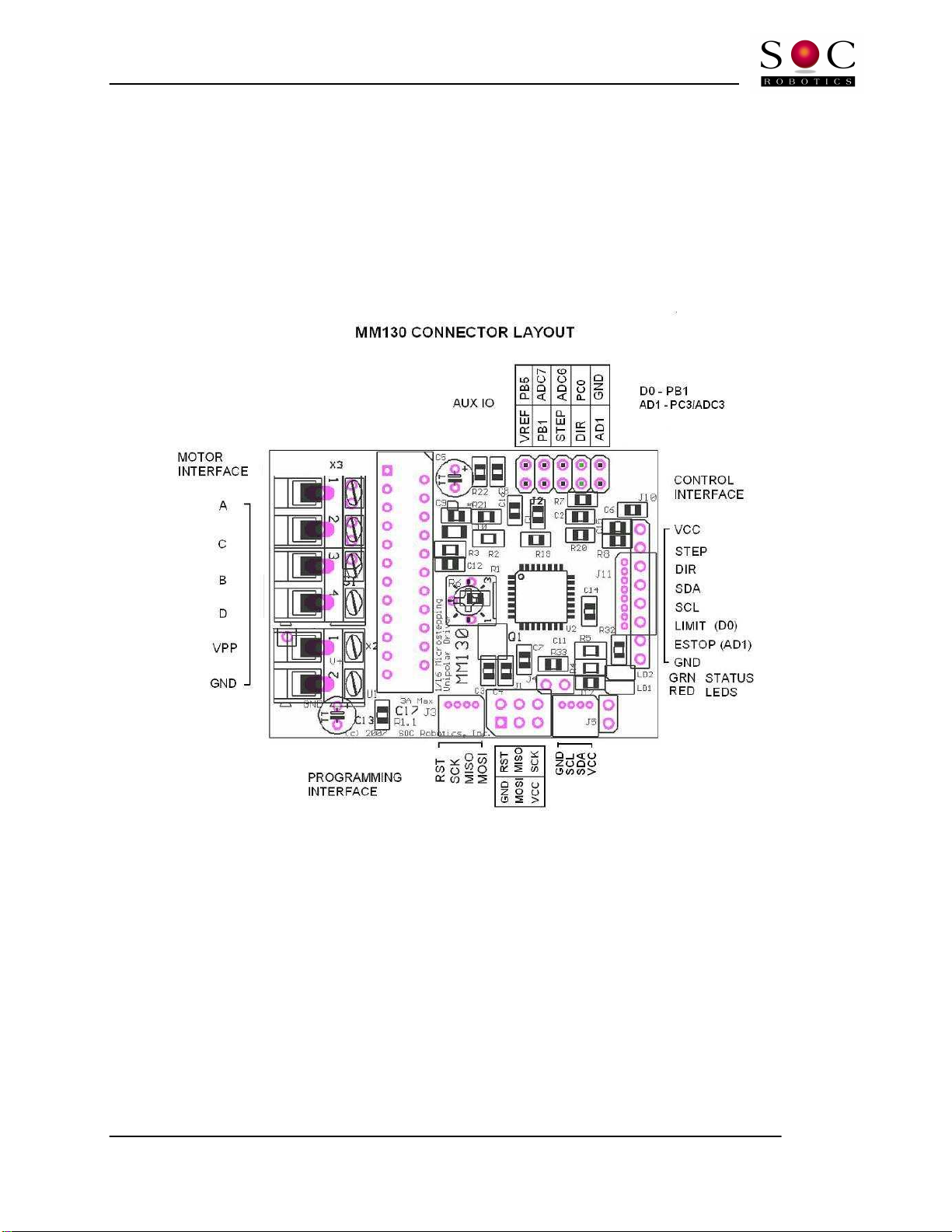
The MM130 has three I/O ports: a motor control port, programming port and an auxiliary IO port as
shown in the connector layout diagram below. Two alternative con igurations o the board are available:
Con iguration 1 replaces the 0.1” motor control port header with an 8 pin picoBlade Molex connector and
con iguration 2 replaces the motor 0.1” motor control port header with a 4 pin picoBlade Molex connector
or the I2C port.

MM130 Technical Reference Manual
© Copyright 2010. SOC Robotics, Inc. 14 Manual Revision 1.01
June 2010
3.2 Motor Control Port
Motor control port is routed to connector J10. Step and direction signals are ed to the board on this port
along with main power (5V DC) and ground, I2C lines and limit switch inputs. The I2C lines (SDA, SCL)
allow a controller such as the MK4USB, MK54 or MK200 to communicate with the MM130 and set
con iguration eatures such as step mode, limit switch recognition, step/direction polarity, etc. The I2C
lines are also routed to a dedicated 4 pin connector. Under so tware control the limit switch inputs can be
monitored and acted on or ignored by the MM130 directly without host intervention. Con iguration
commands can also be encoded in the step/direction lines using a special protocol described later.
Figure 3-3. Step/Direction Control Port Pin Assignment J10.
3.3 Auxiliary IO Port
The auxiliary IO port accepts analog input, digital IO and step/direction inputs. The digital IO can be used
to connect external sensors such as rotary and linear position sensors or to allow the MM130 to control external
devices such as relays. The analog inputs allow the MM130 to measure external analog sensors. The current
software release does not support this functionality but is planned for the next release.
Figure 3-4. Expansion Port Pin Assignment J2.
MM130 Technical Reference Manual
© Copyright 2010. SOC Robotics, Inc. 15 Manual Revision 1.01
June 2010
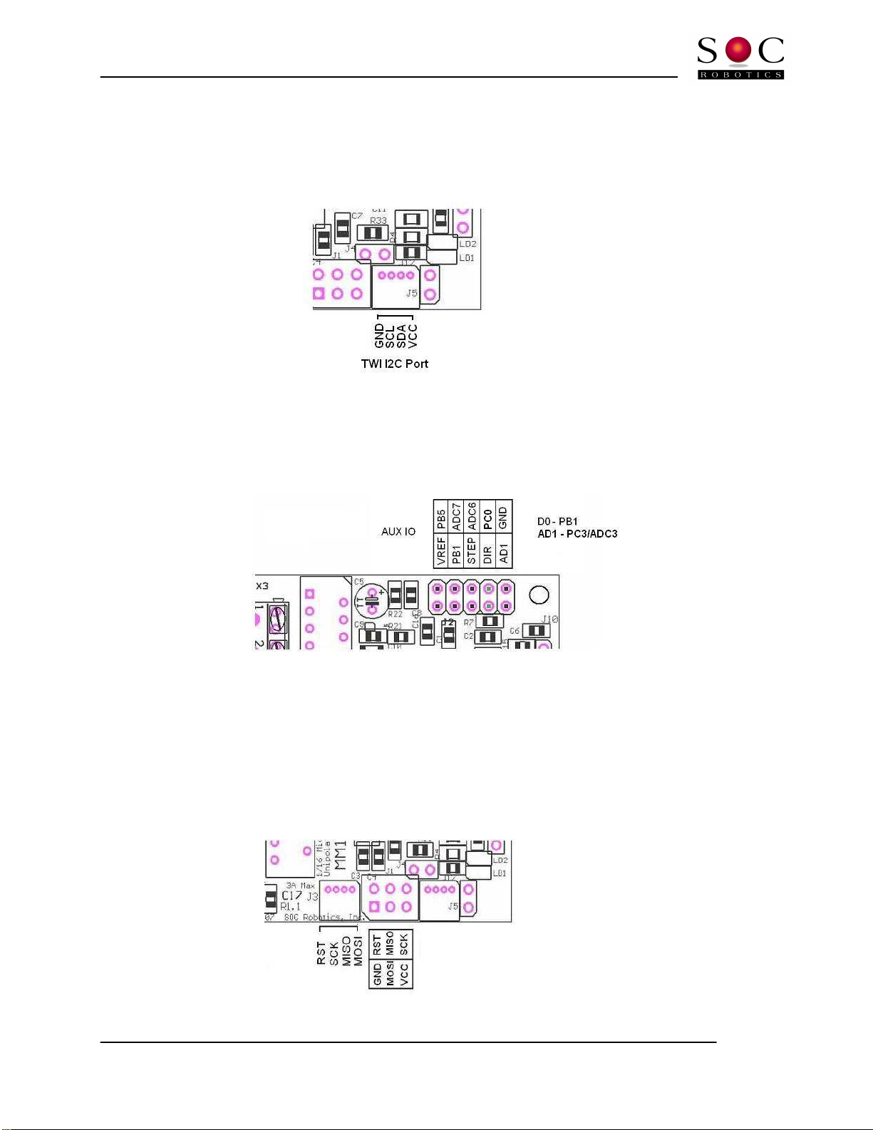
3.4 I2C Expansion Port
The MM130 has an I2C communication port on connector J3. The I2C connector is not installed on the
standard MM130 but is available by special order. The MM130 can be controlled via the I2C port. See
the section o Drive Commands or more in ormation. Note that the I2C signals are also on the Motor
Control Port connector. The MM130 is a slaved I2C device and can be controlled by other SOC Robotics
Smart Peripherals such as joysticks, LCD display controllers data acquisition modules. De ault I2C
address is 0x14 Hex. This address can be changed via the I2C inter ace using special con iguration
commands.
3.5 ISP Programming Port
The MM130 has two ISP Programming ports – a six pin header compatible with the Atmel 6 pin header
ISP programming standard and a our pin picoBlade Molex connector compatible with the USB10U,
MK4, MK14, MK54 and MK200 controllers. The ISP programming port allows the onboard ATmega168
processor Flash to be reprogrammed. See the Atmel ISP programming speci ication or detailed
ATmega168 programming procedures.
Figure 3
-6. ISP Programming Port and MCM-8 programming cable.
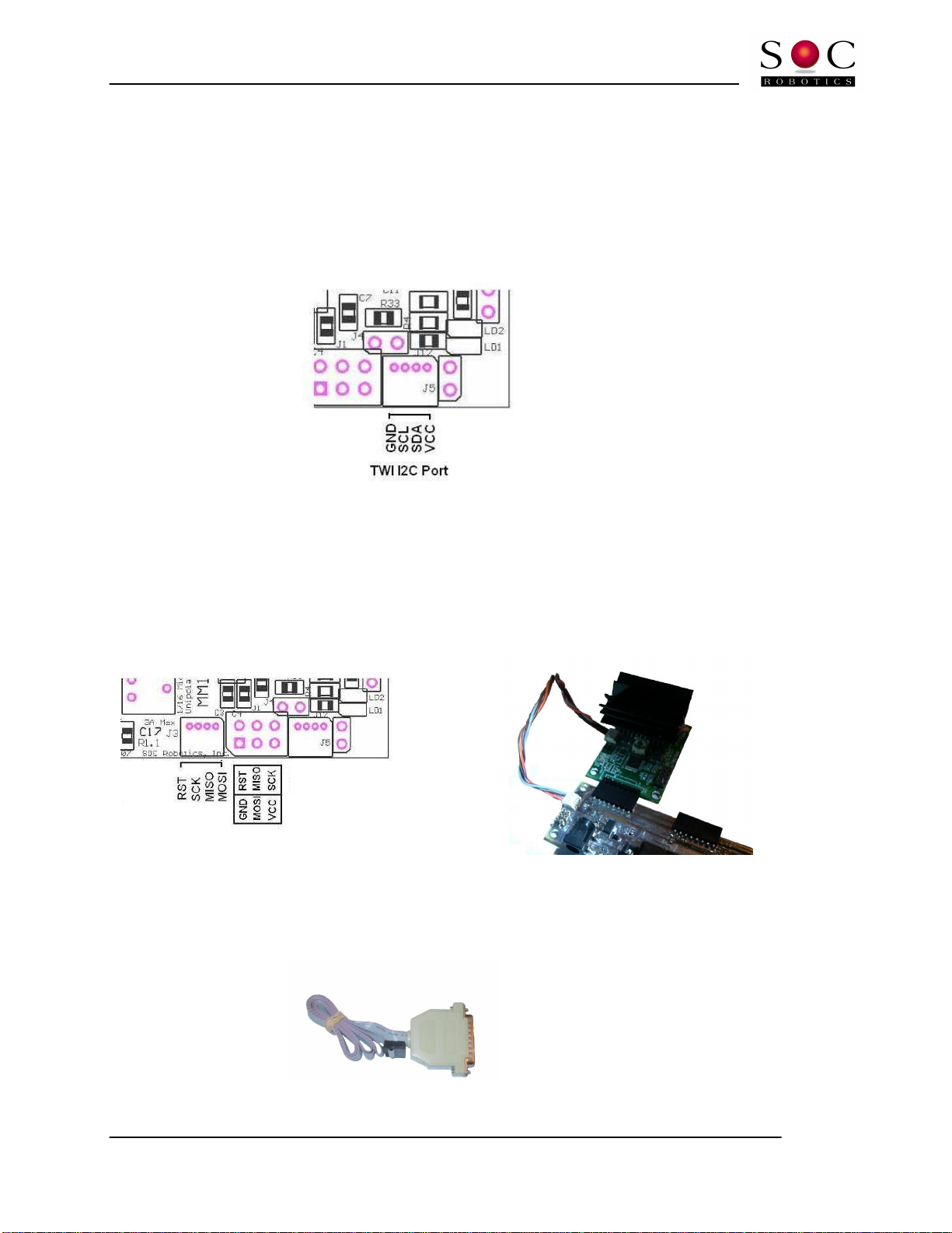
Figure 3
-7. ISP10 Parallel Port programming adapter.
Figure 3
-5. TWI I2C Port with 4 Pin Molex picoBlade Connector.

MM130 Technical Reference Manual
© Copyright 2010. SOC Robotics, Inc. 16 Manual Revision 1.01
June 2010
4.0 Software Operation
4.1 Theory of Operation
The MM130 is driven by step and direction signals applied to connector J10. The MM130 is shipped with
quarter step mode enabled. The MM130 supports ull, wave, hal , quarter, one eighth and one sixteenth
step modes. Step mode can be changed by sending a command to the board via the I2C inter ace or by
sending an encoded command on the step/direction signal lines. The direction signal must be set be ore
the step pulse – the step pulse is a positive going raising edge that is held or at least 5useconds. The
direction signal must not be changed during the step high level or the MM130 will enter Command
Recognition mode.
The MM130 is shipped with a so tware application in which Command Recognition mode is enabled or
the irst ive seconds o operation ollowing power up a ter which Pass Through mode is activated. In
Command Recognition mode all motion control and con iguration setup commands are recognized. In
Pass Through mode the step/direction signals are simply passed through the processor to the SLA7078
driver. In Pass Through mode commands sent to the MM130 are not longer recognized. The MM130
de aults to Pass Through mode a ter 5 seconds to make sure the application so tware driving the MM130
works reliably. I the application driving the MM130 can meet the strict step/direction signal setup and
hold times then Pass Through mode is not required and the more lexible Command Recognition mode
can be used. Pass Through mode should also be used i the cables supplying the step/direction signals to
the MM130 are noise prone. Pass Through mode activation can be changed to Command Recognition
mode in the irst 5 seconds o operation using the ree application GSTepPP.exe available rom our web
site www.soc-robotics.com.
The motor drive chip SLA7078PR is a unipolar microstepping driver with built in current sense resistors
and logic to control drive current given a drive voltage. A potentiometer allows the user to set the
operating point o the driver. The SLA7078 is designed to drive 2-3A motors but should be able to drive
smaller motors without any trouble. The SLA7078 has Motor Coil Short-Circuit Protection and Motor
Coil Open Protection circuits that prevents damage to the device by turning the drive chip o under such
conditions. Power must be cycled to re-enable the chip.
The board power is applied through connector
J10 and requires 5V regulated DC. The standard board runs at 20MHz.
4.2 Auxiliary IO
The MM130 has a number o auxiliary digital and analog inputs plus digital outputs that allow
connection o rotary or linear position sensors and limit switches. The processor can be ield
programmed with new unctions to process signals rom these sensors and limit switches. The current
so tware version does not support external sensors.
4.3 Step Drive Connector
The MM130 controls an attached stepper motor by converting Step and Direction input signals on
connector J10 to our Power Mos ets in the SLA7078PR chip. By de ault the step signal is an active high
pulse lasting at least 5 useconds in Pass Through mode and 20useconds in Command Recognition mode
with optional noise reduction logic implemented in so tware. A high level on the Direction input causes
a clockwise step. De ault step mode is quarter step – step modes can be changed by sending commands
encoded in the step/direction signal lines. I you are experiencing erratic operation then the application
driving the MM130 is probably not meeting the minimum setup and hold times and the MM130 should
be switched to Pass Through mode. In command recognition mode the direction signal can not go low
be ore the step signal goes low – this arms the command recognition logic.
J10 also has I2C and limit/eStop switch inputs. Operation o I2C is described in the next section. Stepper
motor operation can also be controlled through the I2C inter ace independent o signals on J10 and by

MM130 Technical Reference Manual
© Copyright 2010. SOC Robotics, Inc. 17 Manual Revision 1.01
June 2010
recognizing signals encoded on the step/direction lines. Limit/eStop Switch inputs by de ault are not
recognized but can be enabled by the user.
4.4 Driver Commands
The MM130 accepts commands in two di erent communication ormats: commands encoded on the
step/direction lines (step/direction line toggling) and commands sent through the I2C inter ace.
Command Features
A script based parameter con iguration utility allows the user to set the con iguration options o each axis
on an individual basis. Con iguration parameters can be stored in on-chip EEPROM or automatic power
up con iguration control. A special built-in test/setup mode provides a simpli ied method or setting up
the board. Con iguration commands can be sent to the motor controller in real time using a special
communications protocol based on the Step and Direction lines. A bi-directional communication utility
provides a real time link with MM130 processor allowing dynamic change and update o system
parameters on the ly. An API library is available to provide application developers access to the
con iguration eatures o the new so tware.
- New communication protocol or bidirectional data low between the host and MM130 via the
STEP/DIRECTION and Limit Switch lines and I2C
- The ollowing parameters can be set by the user while the MM130 is operating:
o Pass through mode enabled or noisy environments
o Limit switch detection– enable, disable, smart enable, polarity settable
o EStop switch detection– enable, disable, polarity settable
o Step mode selection – wave, ull, hal , quarter, eight, sixteenth
o Automatic motor shut o – enable, disable and time period settable
o Motor power - enable/disable
o Step rate, direction and number o steps to execute
o Maximum step rate
o Distance traveled or each step in inch or metric
o Feed Rate – ipm or cmpm
o Linear or rotary distance commands in inch or metric
o G1 G code commands accepted directly
o Acceleration curve settable
o Single Step - Clockwise or counterclockwise
o Step
Movement Direction Polarity – Clockwise or counterclockwise
o Direction polarity settable – high – clockwise, high –counterclockwise
o Backlash set
o Communication mode – enable/disable
o Save con iguration settings in EEPROM
- Con iguration parameters can be saved in EEPROM
- Stored con iguration parameters can be read rom the motor EEPROM using MK4Prog.exe and
used to create a text based con iguration script ile

MM130 Technical Reference Manual
© Copyright 2010. SOC Robotics, Inc. 18 Manual Revision 1.01
June 2010
Step/Direction Line Toggling
Step/direction line toggling uses the step and direction signal lines to embed commands in step
sequences. I the step and direction inputs are both high and the direction line is brought low be ore the
step line is brought low the driver interprets this to mean a one byte command is about to be sent to the
driver. The step line is then toggled as a clock input while data is encoded on the direction line. The
driver does not interpret this pattern as a series o steps but as a command byte. By sending a string o
bytes in this manner it is possible to send commands to the driver embedded within a stream o step
signals. The exact ormat o the step/direction command byte is shown in the diagram below.
I2C Commands
An alternative communication protocol is to send and receive commands via the I2C inter ace lines. I2C
is a Philips two wire (SDA and SCL) communications protocol that is widely supported by both host
processors and embedded processors. See related documentation or a detailed description o I2C. The
I2C inter ace de aults to address 0x30 but can be changed by sending a broadcast set address command.
Note that each MM130 on a single I2C chain must have a unique address.
Both communication protocols support a common command set. Commands are typically ASCII
character sequences. There are three classes o commands – Setup, Drive and Global. Setup commands
select various con iguration options, Drive commands activate stepper motor operation while Global
commands con igure the communications address o the board and activate a special multiple MM130’s
stepper motor operational state.
4.5 MM130 Command Overview
The MM130 processor responds to commands sent to it via the Step/Direction signal lines. Using a
simple encoding procedure it is now possible to communicate with the Motor Controller via the Step,
Direction and Limit switch lines. All commands are lower case letters and numbers. It is possible to

MM130 Technical Reference Manual
© Copyright 2010. SOC Robotics, Inc. 19 Manual Revision 1.01
June 2010
change Motor Controller operation and con iguration on the ly while the controller is running.
Con iguration changes take e ect immediately.
The MM130 supports the ollowing commands. A detailed description o each command ollows. A
command consists o two or more ASCII characters. Some commands require entry o integer or loating
point numbers. A loating point number entered as an integer is interpreted correctly. Integer or
loating point number must be terminated with a semicolon “;” character. Note that all commands are
lower case characters. Commands are acted on immediately.
On power up the MM130 processor loads con iguration settings rom on chip EEPROM. I these settings
are changed using the commands below the processor does not automatically store the new settings in
EEPROM – the user must explicitly do this using the Save Settings command. I power is lost all changed
settings will be lost i they have not been stored.
A desktop program called GStepPP.exe is used to send commands to the MM130. GStepPP.exe
sends commands to a speci ic axis attached to a MK4 by entering the “c” character ollowing by an axis
identi ier character (x,y,z,a) ollowed by one or more o the command sequences below all entered on one
line. The command is sent to the driver when the enter key is pressed. Command Recognition mode
must be enabled in the driver or commands to be recognized. An example o a command sequence is:
-cxs4
-cxcss
The irst command instructs the x-axis driver to set the step mode to quarter step. The ollowing
command then stores this new setting in EEPROM so the next time the driver is powered up quarter step
mode is activated. A ew o the command unctions can be halted by entering the character sequence
cxq.
I the control so tware driving the MM130 does not need to support command mode then or increased
reliability in noisy environments command recognition mode can be disabled by sending the command
mode disable command cxcci. Once Command Recognition mode has been disable the only way to re-
enable it to re-Flash the processors lash memory using a special programming utility (MK4Prog.exe) and
a special cable.
NOTE: The MM130 is shipped with Command Recognition mode enabled for the
first 5 seconds is to allow you time to change configuration parameters such as
step mode, holding torque shut-off delay, etc without re-flashing the board using
GstepPP.exe. Re-flashing the board requires a special programming utility and
optional cable. Pass Through mode is the most reliable mode in noisy
environments or in situations where you do not know how the host software is
manipulating the step/direction lines.

MM130 Technical Reference Manual
© Copyright 2010. SOC Robotics, Inc. 20 Manual Revision 1.01
June 2010
Command Summary
All commands are printable ASCII characters.
s – Change Step Mode, 1-Full, !-FullF, 2-Hal , @-Hal F, 4-quarter, 8-Eight, 6-Sixteenth cxs4
c – Enter Con iguration Change Mode:
s – Save settings to EEPROM (needs two ‘s’) cxcss
t – Pass through mode, a-active, i-inactive
r – Reset Motor drive chip
h – Turn motor power o
c – Command Recognition mode, a-active, i-inactive
n – Noise reduction mode, a-active, i-inactive
l – loop count or noise reduction – de ault 2, (int)
- Step/direction signals recognition enabled, y–yes, n-no
i – I2C Mode o–on, -o , a-address (int)
e – EStop switch recognition, y–yes, n-no
l – Limit switch recognition, y–yes, s–smart, n–no
p – Step polarity, p-positive, n-negative TBD
d – Direction polarity, c–clockwise, w–counterclockwise
a – Automatic motor power shut o mode, o-on, -o
t – Time a ter which the motor power is shut o , seconds ( loat) cxcat25.5;
b – Set backlash ( loat) cxcb24;
x – Set acceleration parameter ( loat)
m – Step resolution parameters
r – Resolution ( loat), cxcmr0.000125;
n – Minimum pps ( loat), cxcmn20.0;
x – Maximum pps ( loat), cxcmx2300;
m – Ramp rate ( loat)
d – Drive Motor Commands
z – Zero absolute position
g – Step continuously until told to stop
h – Go to Home position, n-near side, - ar side, o-o set ( loat)
i - Set eed rate (ipm), loat cxdi10.0;
s – Set step rate (pps), loat cxds125;
p – Pause execution (msec), int cxdp1000;
c – Step clockwise
w – Step counterclockwise
l – Set slow step rate (pps), loat
– Set ast step rate (pps), loat
m – Constant step cxdmw220000;1300;
direction, stepmode, number o steps, step rate (pps)
x – Ramp or n loops using de ault low high pps cxdx220;2000;4;
stepmode, steps at each speed, constant step number, loops
r – Ramp between low and high pps cxdr2300;2000;20;2000;
stepmode, slow step rate, high step rate, step increment, constant steps
d – Distance mode cxdd21.25;6.27;
stepmode, new position, eed rate (ipm)
t – Enter Test Mode
t – Toggle back and orth – all step modes, hit any key to exit
x – Ramp low to high – high to low – all step modes, hit any key to exit
Table of contents
Popular Control Unit manuals by other brands


Dungs
Dungs FRM 100025 instruction manual

Parker
Parker EP Series Pro-Bloc Installation and operation manual

H3C
H3C SecBlade user manual

Allen-Bradley
Allen-Bradley MicroLogix 1200 installation instructions

NPI
NPI GIA-05X Operating instructions and system description

Dungs
Dungs GasMultiBloc MB-VEF B01 instructions

Emerson
Emerson Keystone K-Lok 360 Series Installation, Operation, Maintenance and Troubleshooting

Intertec Data Systems
Intertec Data Systems MPR-A Series instruction sheet

Bosch
Bosch ACS 611 Original instructions

Interlogix
Interlogix NX-595E installation manual

Sanela
Sanela SLT 07 quick start guide

JAUDT
JAUDT DPK GII 6207 Series Translation of the original operating instructions