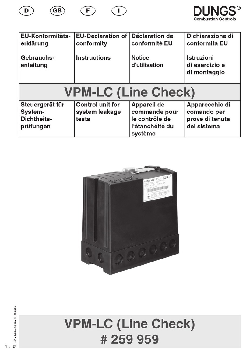
manuals.online logo
Brands
  1. Home
  2. •
  3. Brands
  4. •
  5. Dungs
  6. •
  7. Control Unit
  8. •
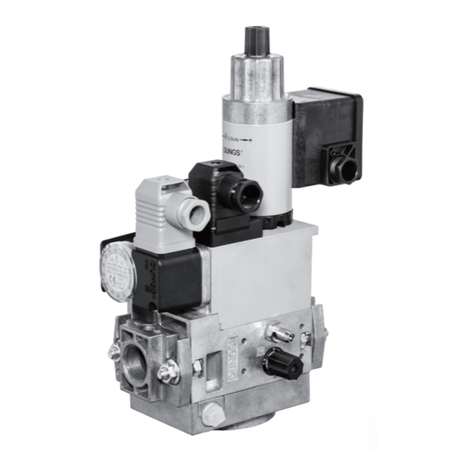
  9. Dungs GasMultiBloc MB-VEF B01 User manual

Dungs GasMultiBloc MB-VEF B01 User manual

Other manuals for GasMultiBloc MB-VEF B01

1

This manual suits for next models

3

Other Dungs Control Unit manuals

Dungs VDK 200 Service manual

Dungs

Dungs VDK 200 Service manual

Dungs DMK 5040 Service manual

Dungs

Dungs DMK 5040 Service manual

Dungs VDK 200 A S02 Service manual

Dungs

Dungs VDK 200 A S02 Service manual

Dungs DMV Series User manual

Dungs

Dungs DMV Series User manual

Dungs MPA 5111 User manual

Dungs

Dungs MPA 5111 User manual

Dungs DMV 11 eco Series Service manual

Dungs

Dungs DMV 11 eco Series Service manual

Dungs MB-ZR B07 Series User manual

Dungs

Dungs MB-ZR B07 Series User manual

Dungs FRSBV 20010 Series User manual

Dungs

Dungs FRSBV 20010 Series User manual

Dungs MV X Product guide

Dungs

Dungs MV X Product guide

Dungs SV-DLE 1005/604 Service manual

Dungs

Dungs SV-DLE 1005/604 Service manual

Dungs FRM 100025 User manual

Dungs

Dungs FRM 100025 User manual

Dungs VPM-VC User manual

Dungs

Dungs VPM-VC User manual

Dungs SAV 100065 MD User manual

Dungs

Dungs SAV 100065 MD User manual

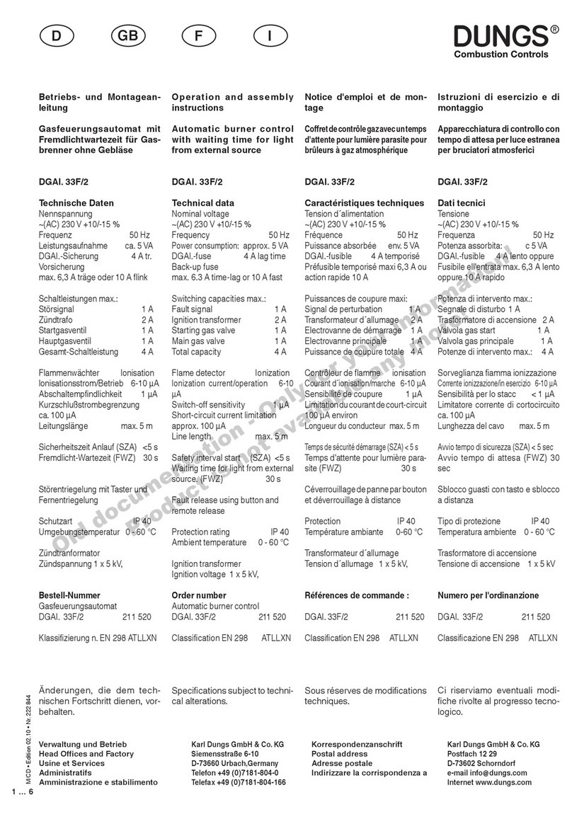
Dungs DGAI. 33F/2 Service manual

Dungs

Dungs DGAI. 33F/2 Service manual

Dungs FRSBV User manual

Dungs

Dungs FRSBV User manual

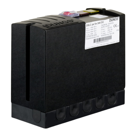
Dungs DSLC px Vx Service manual

Dungs

Dungs DSLC px Vx Service manual

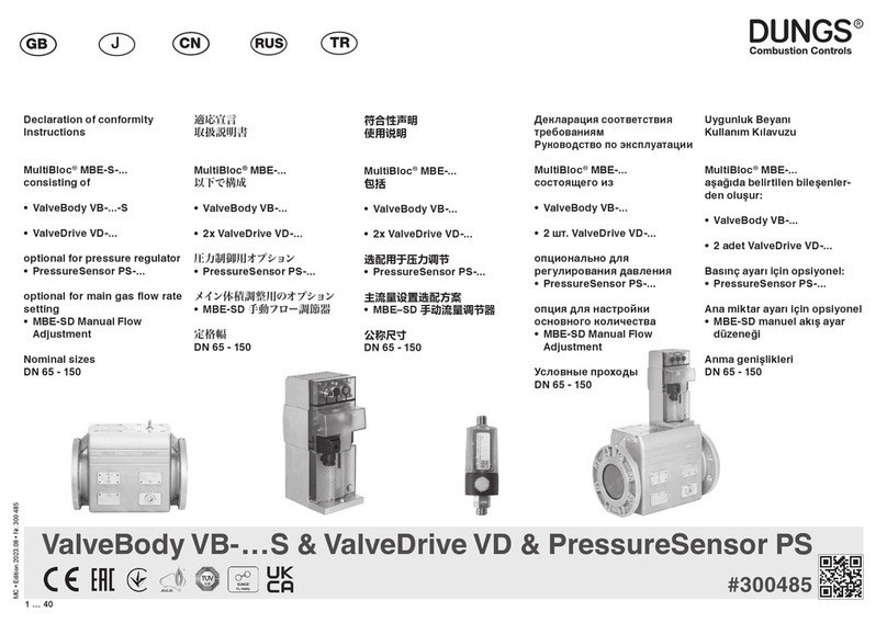
Dungs MultiBloc MBE-S Series User manual

Dungs

Dungs MultiBloc MBE-S Series User manual

Dungs VPM-VC User manual

Dungs

Dungs VPM-VC User manual

Dungs GasMultiBloc MBC-65 Series User manual

Dungs

Dungs GasMultiBloc MBC-65 Series User manual

Dungs VPM-LC User manual

Dungs

Dungs VPM-LC User manual

Dungs HPSV 10020/604 User manual

Dungs

Dungs HPSV 10020/604 User manual

Dungs SAV 100065 User manual

Dungs

Dungs SAV 100065 User manual

Dungs DMV-D(LE) 704/6x4 Series User manual

Dungs

Dungs DMV-D(LE) 704/6x4 Series User manual

Dungs VPM-VC Service manual

Dungs

Dungs VPM-VC Service manual

Popular Control Unit manuals by other brands

Seitz 14A80 user manual

Seitz

Seitz 14A80 user manual

Wilo RS485 Installation and operating instructions

Wilo

Wilo RS485 Installation and operating instructions

Becker CentralControl CC41 Commissioning Instruction

Becker

Becker CentralControl CC41 Commissioning Instruction

SICK CDB650 operating instructions

SICK

SICK CDB650 operating instructions

Panduit NetKey NKP5E88M Series installation instructions

Panduit

Panduit NetKey NKP5E88M Series installation instructions

MX Options Concentric Petite Fitting instructions

MX

MX Options Concentric Petite Fitting instructions

Clean Water Systems Fleck 2510 Installation & start?up guide

Clean Water Systems

Clean Water Systems Fleck 2510 Installation & start?up guide

Fairchild FSB44104A user guide

Fairchild

Fairchild FSB44104A user guide

LEGRAND Wattstopper LMIN-104 installation instructions

LEGRAND

LEGRAND Wattstopper LMIN-104 installation instructions

PMK ATT10BNCS instruction manual

PMK

PMK ATT10BNCS instruction manual

Tektronix TDS3FFT user manual

Tektronix

Tektronix TDS3FFT user manual

Woodward easYgen Technical manual

Woodward

Woodward easYgen Technical manual

Balluff BNI EIP-502-105-R015 user guide

Balluff

Balluff BNI EIP-502-105-R015 user guide

NXP Semiconductors TWR-LS1021A Getting started

NXP Semiconductors

NXP Semiconductors TWR-LS1021A Getting started

Advantech PCM-3117 Startup manual

Advantech

Advantech PCM-3117 Startup manual

Danfoss MCO 101 manual

Danfoss

Danfoss MCO 101 manual

Moons' Lin Engineering R701P user manual

Moons'

Moons' Lin Engineering R701P user manual

Aventics RV1 operating instructions

Aventics

Aventics RV1 operating instructions

manuals.online logo
manuals.online logoBrands
  • About & Mission
  • Contact us
  • Privacy Policy
  • Terms and Conditions

Copyright 2025 Manuals.Online. All Rights Reserved.

MC • Edition 03.19 • Nr. 223 938
1 … 20
HR SRB BIH SK
EU-Konformitäts-
erklärung
Gebrauchs-
anleitung
EU-Declaration of
conformity
Instructions
Déclaration de
conformité EU
Notice
d’utilisation
Dichiarazione di
conformità EU
Istruzioni
di esercizio e
di montaggio
MB-VEF B01
GasMultiBloc®
stufenlos gleiten-
de Betriebsweise
GasMultiBloc®
Gas-air-ratio
control
MultiBloc®
Réglage combiné
du gaz et de l'air
GasMultiBloc®
con funzionamen-
to a modulazione
continua
Nennweiten
Nominal diameters
Diamètres nominaux
Diametri nominali
Rp 1 ½ - Rp 2
MB-VEF B01
# 223 938
2 … 20
MC • Edition 03.19 • Nr. 223 938
HR SRB BIH SK
EU-Konformitäts-
erklärung
EU Declaration of
conformity
Déclaration de
conformité EU
Dichiarazione di
conformità EU
Produkt / Product
Produit / Prodotto MB-VEF B01
GasMultiBloc®
stufenlos gleitende Betriebsweise
GasMultiBloc®Gas-air-ratio control
MultiBloc®Réglage combiné du gaz et de l'air
GasMultiBloc®con funzionamento a modulazione continua
Hersteller / Manufacturer
Fabricant / Produttore Karl Dungs GmbH & Co. KG
Karl-Dungs-Platz 1
D-73660 Urbach, Germany
bescheinigt hiermit, dass die in die-
ser Übersicht genannten Produkte
einer EU-Baumusterprüfung un-
terzogen wurden und die wesentli-
chenSicherheitsanforderungender:
EU-Gasgeräteverordnung
2016/426
EU-Druckgeräterichtlinie
2014/68
in der gültigen Fassung erfüllen.
Bei einer von uns nicht freigegebe-
nen Änderung des Gerätes verliert
diese Erklärung ihre Gültigkeit.
certies herewith that the products
named in this overview were sub-
jected to an EU Type examina-
tion and meet the essential safety
requirements:
EU Gas Appliances Regulation
2016/426
EU Pressure Equipment Directive
2014/68
as amended.
In the event of an alteration of the
equipment not approved by us this
declaration loses its validity.
certifie par la présente que le
produit mentionné dans cette vue
d'ensemble a été soumis à un
examen de type de l'UE et qu'il
est conforme aux exigences en
matières de sécurité des dernières
versions en vigueur de :
l'ordonnance de l'UE relative
aux appareils au gaz
2016/426
à la directive UE « Équipements
sous pression »
2014/68
Ce communiqué n'est plus valable
si nous eectuons une modication
libre de l'appareil.
Con la presente si certica che i
prodotti citati in questa panoramica
sono stati sottoposti a una prova di
omologazione UE e che i requisiti
di sicurezza essenziali:
regolamento UE sugli apparecchi
a gas
2016/426
direttiva UE sulle attrezzatture
a pressione
2014/68
sonosoddisfattinellaversionevalida.
In caso di modica dell'apparecchio
nonammessa,questadichiarazione
perde di validità.
Prüfgrundlage der EU-Baumusterprüfung
Specied requirements of the EU Type examination
Base d'essai de l'examen de type de l'UE
Criteri di prova dell'omologazione UE
EN 126
ISO 23551-8
Gültigkeitsdauer/Bescheinigung
Term of validity/attestation
Validité/certicat
Durata della validità/Attestazione
2025-10-08
CE0036
2028-04-09
CE-0123CT1146
Notizierte Stelle
Notied Body
Organisme notié
Organismo noticato
2014/68/EU
TÜV SÜD Industrie Service
GmbH
Westendstraße 199
D-80686 München
Germany
Notied Body number: 0036
(EU) 2016/426
TÜVSÜDProductService GmbH
Zertizierstellen
Ridlerstraße 65
D-80339 München
Germany
Notied Body number: 0123
Überwachung des QS-Systems
Monitoring of the QA system
Contrôle du système d'assurance qualité
Monitoraggio del sistema QS
Gewähltes Konformitätsverfahren
Modul B+D
Conformity process adopted:
Module B+D
Procédure de conformité sélection-
née : module B+D
Procedura di conformità seleziona-
ta: modulo B+D
Dr.-Ing. Karl-Günther Dalsaß,
Geschäftsführer / Chief Operating Ocer
Directeur / Amministratore
Urbach, 2018-04-21
MC • Edition 03.19 • Nr. 223 938
3 … 20
4 … 20
MC • Edition 03.19 • Nr. 223 938
5 … 20
Betriebs- und Montage-
anleitung
GasMultiBloc®
stufenlos gleitende
Betriebsweise
Typ MB-VEF B01
Nennweiten
Rp 1 1/2 - Rp 2
Operation and assembly
instructions
GasMultiBloc®
Gas-air-ratio control
Type MB-VEF B01
Nominal diameters
Rp 1 1/2 - Rp 2
Notice d'emploi et de
montage
GasMultiBloc®
Réglage combiné du gaz
et de l'air
Typ MB-VEF B01
Diamètres nominaux
Rp 1 1/2 - Rp 2
Istruzioni di esercizio e di
montaggio
GasMultiBloc®
con funzionamento a mo-
dulazione continua
Tipo MB-VEF B01
Diametri nominali
Rp 1 1/2 - Rp 2
Einbaulage
Installation position
Position de montage
Posizione di montaggio
Max. Betriebsdruck 360 mbar (36 kPa)
Max. operating pressure 360 mbar (36 kPa)
Pression de service maxi. 360 mbar (36 kPa)
Max. pressione di esercizio 360 mbar (36 kPa)
S10/12: p
e,min.
5 mbar (0,5 kPa) – p
e,max.
100 mbar (10 kPa)
S30/32:p
e,min.
100mbar(10 kPa)–p
e,max.
360mbar(36 kPa)
V1+V2 Klasse A, Gruppe 2
V1+V2 Class A, Group 2
V1+V2 Classe A, Groupe 2
V1+V2 Class A, Gruppo 2
nach / acc. / selon / a norme
EN 161
Klasse A, Gruppe 2
Class A, Group 2
Classe A, Groupe 2
Class A, Grupo 2
nach / acc. / selon / a norme
EN 88-1, EN 12067-1
Un~(AC) 220 V-15 % …- 230 V+10 %
Einschaltdauer/Switch-onduration/
Durée de mise sous tension/Durata
inserzione 100 %
Verhältnis V
ratio V
Rapport V
rapporto valore V
pBr : pL
0,75 : 1 … 3 : 1
Nullpunktkorrektur N
Zero point adjustment N
Réglage du point zéro N
Spostamento a punto zero N
≈ ± 1 mbar (0,1 kPa)
Umgebungstemperatur
Ambient temperature
Température ambiante
Temperatura ambiente
-15 °C … +70 °C
Schutzart
Degree of protection
Protection
Protezione
IP 54 nach / acc. / selon / a norme
EC 529 ( DIN 40 050)
Familie 1 + 2 + 3
Family 1 + 2 + 3
Famille 1 + 2 + 3
Famiglia 1 + 2 + 3
Ausgangsdruckbereich
Output pressure range
Pression de sortie
Campo pressione in uscita
0,5 - 100 mbar (0,05 - 10 kPa)
[mbar]
EN 161
[ V ]
EN 88
V
1 : 1
IEC 529IEC 529
HR SRB BIH SK
Elektrischer Anschluß
Electrical connection
Raccordement électrique
Allacciamento elettrico
IEC 730-1 (VDE 0631 T1)
Erdung nach örtlichen Vorschriften
Grounding acc. local regulations
Mise à la terre selon normes locales
Messa a terra secondo prescrizioni locali
S 10/S 30
P1
L1
P2
L2
Mp
N
P1
L1
Mp
N
P1
L1
P2
L2
Mp
N
P1
L1
Mp
N
S 12/S 32
P1
L1
MP
N
2
1
P2
L2
P1
L1
MP
N
1
2
3
6 … 20
MC • Edition 03.19 • Nr. 223 938
Einbaumaße / Dimensions / Cotes d'encombrement / Dimensioni [mm]
MB-VEF 415/420
Typ
Type
Type
Tipo
MB-VEF 415 B01
MB-VEF 420 B01
MB-VEF 425 B01
Rp
Rp 1 1/2
Rp 2
Rp 2
Önungszeit
Opening time
Durée d'ouverture
Tempo aperture
< 1 s
< 1 s
< 1 s
Pmax.
[VA]
50
90
110
A
Platzbedarf für Deckel des
Druckwächters
B
Platzbedarf für Magnetwech-
sel
A
Space requirement for pressure
switch cover
B
Space requirements for tting
solenoid
A
Encombrementpourlecouvercle
du pressostat
B
Encombrement pour le rempla-
cement de la bobine
A
Ingombro per il coperchio del
pressostato
B
Ingombro per sostituzione
bobina
Imax.
[A]
~(AC)
220 V .. 240 V
0,37
0,37
0,46
Gewicht
Weight
Poids
Peso [kg]
6,4
7,4
13,5
MB-VEF 425
Einstellzeit
Setting time
Temps de réglage
Tempo di regolazione
EN 12067-1
< 1 s
< 1 s
< 1 s
Schaltungen/h
Switching/h
Enclenchements/h
Interventi/h
60
60
60
MC • Edition 03.19 • Nr. 223 938
7 … 20
Druckabgrie
Pressure taps
Prises de pression
Presa di pressione
MB-VEF 415
MB-VEF 420
1, 2, 3, 4, 5
Verschlußschraube G 1/8
G 1/8 screwed seal plug
Bouchon G 1/8
Tappo a vite G 1/8
6, 7, 8
Impulsleitungen pL, pF ,pBr
Pulse lines pL, pF ,pBr
Raccordement des pressions pL, pF ,pBr
Linee ad impulsi pL, pF ,pBr
9
Meßstutzen
Test nipple
Prise de pression
Presa per misuratore
max. Drehmomente / Systemzubehör
max. torque / System accessories
max. couple / Accessoires du système
max. coppie / Accessorio di sistema
M 5
5 Nm
M 6
7 Nm
G ⅛
5 Nm
G ¼
7 Nm
G ½
10 Nm
G ¾
15 Nm
M 8
15 Nm
M 4
2,5 Nm
Geeignetes Werkzeug einsetzen! Schrauben kreuzweise anziehen!
Please use proper tools! Tighten screws crosswise!
Utiliser des outils adaptés! Serrer les vis en croisant!
Impiegare gli attrezzi adeguati! Stringere le viti incrociate!
DN
Rp
Mmax.
Tmax.
Gerät darf nicht als Hebel be-
nutzt werden
Do not use unit as lever.
Ne pas utiliser la vanne comme
un levier.
L'apparecchio non deve essere
usato come leva.
25
1
340
125
32
1 1/4
475
160
40
1 1/2
610
200
50
2
1100
250
[Nm] t ≤ 10 s
[Nm] t ≤ 10 s
MB-VEF 425
Mmax.
Mmax.
Tmax.
Tmax.
[Nm]
18
19
ChromeSteelMadeinGermany
M 3
1,2 Nm
8 … 20
MC • Edition 03.19 • Nr. 223 938
Übersicht / Overview / Tableau récapitulatif / Sommario
MB-VEF 415/420
1
2
3
4
5
6
7
8
9
10
11
12
13
14
15
16
17
18
Elektrischer Anschluß Druck-
wächter DIN EN 175 301-803
ElektrischerAnschlußVentile
DIN EN 175 301-803
Druckwächter
Eingangsansch
Druckanschluß G 1/8 vor
Filter
Filter
Typenschild
Druckanschluß G 1/8
Gebläsedruck pL
Einstellschraube
Verhältnis V
peMeßanschluß G 1/8 vor
V1, beidseitig möglich
Meßanschluß G 1/8
nach V2
Einstellschraube
Nullpunktkorrektur N
Druckanschluß G 1/8
Feuerraumdruck pF
Druckanschluß G 1/8
Brennerdruck pBr
Ausgangsansch
paMeßanschluß G 1/8 nach
V1, beidseitig möglich
Betriebsanzeige
Impulsleitung
Electrical connection for pressure
switch DIN EN 175 301-803
Electricalconnection forvalvesDIN
EN 175 301-803
Pressure switch
Input ange
Pressure connection G 1/8 up-
stream of lter
Filter
Type plate
G 1/8 pressure connection for pL
blower pressure
Setting screw, ratio V
Test point connection G 1/8 downstream
of lter possible on both sides
Test point connection G 1/8 down-
stream of V2
Setting screw, zero point adjust-
ment N
G 1/8 pressure connection for pF
furnace pressure
G 1/8 pressure connection for pBr
burner pressure
Output ange
Test point connection G 1/8 downstream
of V1, possible on both sides
Operation display
Pulse line
Allacciamento elettrico pressostato
DIN EN 175 301-803
Allacciamentoelettricovalvole DIN
EN 175 301-803
Pressostato
Flangia in entrata
Attacco pressione G 1/8 prima
del ltro
Filtro
Targhetta
Attacco pressione G 1/8 per pres-
sione alla ventola pL
Vite di regolazione per rapporto
valore V
Attacco misuratore G 1/8 possible
sui due lati prima della V1
Attacco misuratore G 1/8 dopo V2
Vite di regolazione per correzione
punto zero
Attacco pressione G 1/8 per pres-
sione al vano caldaia pF
Attacco pressione G 1/8 per pres-
sione al bruciatore pBr
Flangia in uscita
Possibile attacco misuratore G1/8
dopo V1 su entrambi i lati
indicatore di esercizio
Linee ad impulsi
Raccordement électrique du pres-
sostat DIN EN 175 301-803
Raccordement électrique de l'élec-
trovanne DIN EN 175 301-803
Pressostat
Bride d'entrée
Prise de pression G 1/8 avant le
ltre
Filtre
Plaque signalétique
Raccordement G 1/8 pour la pres-
sion d'air pL
Vis de réglage du rapport V
Prise de pression G 1/8 avant V1,
possible des deux côtés
Prise de pression G 1/8 après V2
Vis de réglage de la correction du
point zéro N
Raccordement G1/8 pour la pres-
sion du foyer pF
Raccordement G 1/8 pour la pres-
sion du brûleur pBr
Bride de sortie
Prise de pression après V1 possible
des deux côtés
Indicateur de marche
conduite d'impulsions
Impulsleitungen sind nicht Bestandteil des Lieferumfangs.
Pulse lines are not part of our scope of delivery.
Notre fourniture ne comprend pas la tuyauterie de raccordement.
Le linee ad impulsi non costituiscono parte integrante della normale fornitura.
2
7
8
18
911
10 12 18
13
14
18
15
17 16
1
3
5
4
6
MC • Edition 03.19 • Nr. 223 938
9 … 20
Gewindeanschausführung
MB- VEF B01
Ein- und Ausbau
1. Flansche auf die Rohrleitungen
montieren.GeeigneteDichtmittel
verwenden, Bild 1.
2.MB-VEFB01einsetzen,Lageder
O-Ringe beachten, Bild 2.
3. Schrauben A – H anziehen.
4. Impulsleitungen pL, pF und pBr
anbringen.
5. Nach Einbau Dichtheits- und
Funktionskontrolle.
6. Ausbau in umgekehrter Reihen-
folge 4 è3 è2 è1.
Threaded ange version
MB-VEF B01
Installation and disassembly
1. Mount ange onto tube lines. Use
appropriate sealing agent
(see Fig. 1)
2. Insert MB-VEF B01. Note position
of O rings (see Fig. 2).
3.Tighten screws A – H
4. Attach pulse lines pL, pFand
pBr.
5. After installation, perform leakage
and functional test.
6. Disassembly in reverse order
4 è3 è2 è1.
Version à brides taraudées
MB- VEF B01
Montage / Démontage
1. Visser les brides sur la tuyauterie,
utiliser de la pâte à joints appro-
priée Fig 1
2. Mise en place du MB-VEF, attention
aux joints toriques Fig 2.
3. Serrer les vis A – H
4. Raccorder les conduites d'impul-
sions pL, pF
, pBr .
5. Contrôle de l'étanchéité et des
fonctions.
6. Pour le démontage suivre les
instructions dans le sens inverse
4 è3 è2 è1.
Esecuzione flangia filettata
MB-VEF B01
Montaggio e smontaggio
1. montare la angia sulla tubazio-
ne. Utilizzare per questo mastici
adeguati: Fig.1
2. inserire l'apparecchio MB-VEF
B01 e prestare particolare atten-
zione agli O-Ring: Fig 2.
3. stringere le viti A – H
4. montare le linee ad impulsi pL,
pF e pBr .
5. dopo il montaggio controllare la
tenuta ed il funzionamento.
6. lo smontaggio va effettuato
esattamente in senso inverso:
4 è3 è2 è1.
1 2
3 4
pBr
pF
pL
A
B
E
F
D
C
H
G
10 … 20
MC • Edition 03.19 • Nr. 223 938
Montagevorschrift
Impulsleitungen
Impulsleitungen pL, pFund
pBR müssen ≥ DN 4 (ø 4 mm),
PN 1 entsprechen und aus Stahl
gefertigt sein.
Andere Werkstoe der Impulslei-
tungen nur nach Baumusterprü-
fungzusammenmitdemBrenner
zulässig.
Impulsleitungen müssen so
verlegt werden, daß kein
KondensatindenMB-VEFzurück-
ießen kann.
Impulsleitungen müssen
sicher gegen Abriß und Ver-
formung verlegt sein.
Impulsleitungen kurz halten!
Leitungen/Impulsleitungen
nach Anschluß auf atmosphä-
rische Dichtheit prüfen, Lecksuch-
spray nur gezielt einsetzen.
Prüfdruck: pmax. = 100 mbar
Pulse line
assembly instructions
Pulse lines pL, pF and pBR
must correspond to ≥ DN 4
(4 mm dia.), PN 1 and they must
be made of steel.
Other materials for pulse lines
are only permitted after a type
test together with the burner.
Route pulse lines so that no
condensate can ow back
to the MB-VEF.
Secure pulse lines to prevent
them from being ripped out
and deformed.
Keep pulse lines short!
Test lines/impulse lines for
leakage to air. Use leakage
spray only if necessary.
Test pressure: p
max.
= 100 mbar
Instructions de montage des
conduites d'impulsions
Les conduites d'impulsions
pL, pF et pBR doivent être en
acier et avoir au moins PN1 et DN4.
Des conduites d'impulsions autres
qu'enacierne pourrontêtreutilisées
qu' après des essais et une homolo-
gation avec le brûleur.
Le montage des conduites d'impul-
sions doit être réalisé an
d'éviter que des condensats
s'introduisent dans le MB-VEF.
Les conduites d'impulsions doivent être
protégées contre l'arrachement
et la déformation.
Les conduites d'impulsions
doivent être les plus courtes
possible!
Un contrôle d'étanchéité des conduites
sera réalisé après le montage.
Attention dans l'utilisation d'un
spray de détection de fuite.
Pression de contrôle: p
max.
= 100 mbar
Prescrizioni per il montaggio
delle linee ad impulsi
Le linee ad impulsi pL, pF e p BR
devono essere ≥ a DN 4 (ø
4 mm), e corrispondere a PN 1 ed
essere prodotte in acciaio.
Altri materiali delle linee ad impulsi
sono consentiti soltanto dopo che
si sarà potuto collaudarne un cam-
pione insieme al bruciatore.
Le linee ad impulsi dovranno
essere strutturate in modo
tale che non sia possibile l'inltra-
zionedicondensa nell'apparecchio
MB-VEF.
Le linee ad impulsi dovranno
essere a prova di rottura e di
deformazione.
Mantenereperlelinee ad impulsi
un percorso breve
Dopo l'allacciamento con-
trollare la tenuta atmosferica
delle condutture e delle linee ad
impulsi. Usare gli spray cercafughe
soltanto in modo orientato.
Pressione di prova: p
max.
= 100 mbar
1 pe: Gaseingangsdruck
S10/12: 5 - 100 mbar
S30/32:100 - 360 mbar
6 pL: Gebläsedruck, Luft
0,4 - 100 mbar
7 pF: Feuerraumdruck
– 20 mbar … + 50 mbar
oder Atmosphäre
∆p
L
max. = p
L
- p
F
= 100 mbar
∆p
BR
max. = p
L
- p
F
= 100 mbar
8 pBr: Brennerdruck, Gas
0,5 - 100 mbar
1 pe: Gas inlet pressure
S10/12: 5 - 100 mbar
S30/32:100 - 360 mbar
6 pL: Blower pressure, air
0,4 - 100 mbar
7 pF: Combustion chamber
pressure or atmosphere
– 20 mbar … + 50 mbar
∆p
L
max. = p
L
- p
F
= 100 mbar
∆p
BR
max. = p
L
- p
F
= 100 mbar
8 pBr: Burner pressure, gas
0,5 - 100 mbar
1
pe: Pression d'entrée du gaz
S10/12: 5 - 100 mbar
S30/32:100 - 360 mbar
6 pL: Pression de l'air
0,4 - 100 mbar
7 pF: Pression du foyer
– 20 mbar … + 50 mbar
ou pression atmosphérique
∆p
L
max. = p
L
- p
F
= 100 mbar
∆p
BR
max. = p
L
- p
F
= 100 mbar
8
pBr: Pression du brûleur, gaz
0,5 - 100 mbar
1
pe: pressione gas in entrata
S10/12: 5 - 100 mbar
S30/32:100 - 360 mbar
6
p
L
: pressione al soante, aria
0,4 - 100 mbar
7
pF: pressione al vano caldaia
– 20 mbar … + 50 mbar
o atmosfera
∆p
L
max. = p
L
- p
F
= 100 mbar
∆p
BR
max. = p
L
- p
F
= 100 mbar
8
pBr: pressione al bruciatore,
gas 0,5 - 100 mbar
MB-VEF 415/420
Einbau Impulsleitungen
Installation of pulse lines
Montage des conduites d'impulsions
Installazione delle linee ad impulsi