Socket & See DCF200 User manual

Instruction Manual & Specification
DCF200
Dead Circuit Finder
SS0018V2 Sn
2
SS0018V2
1. Safety
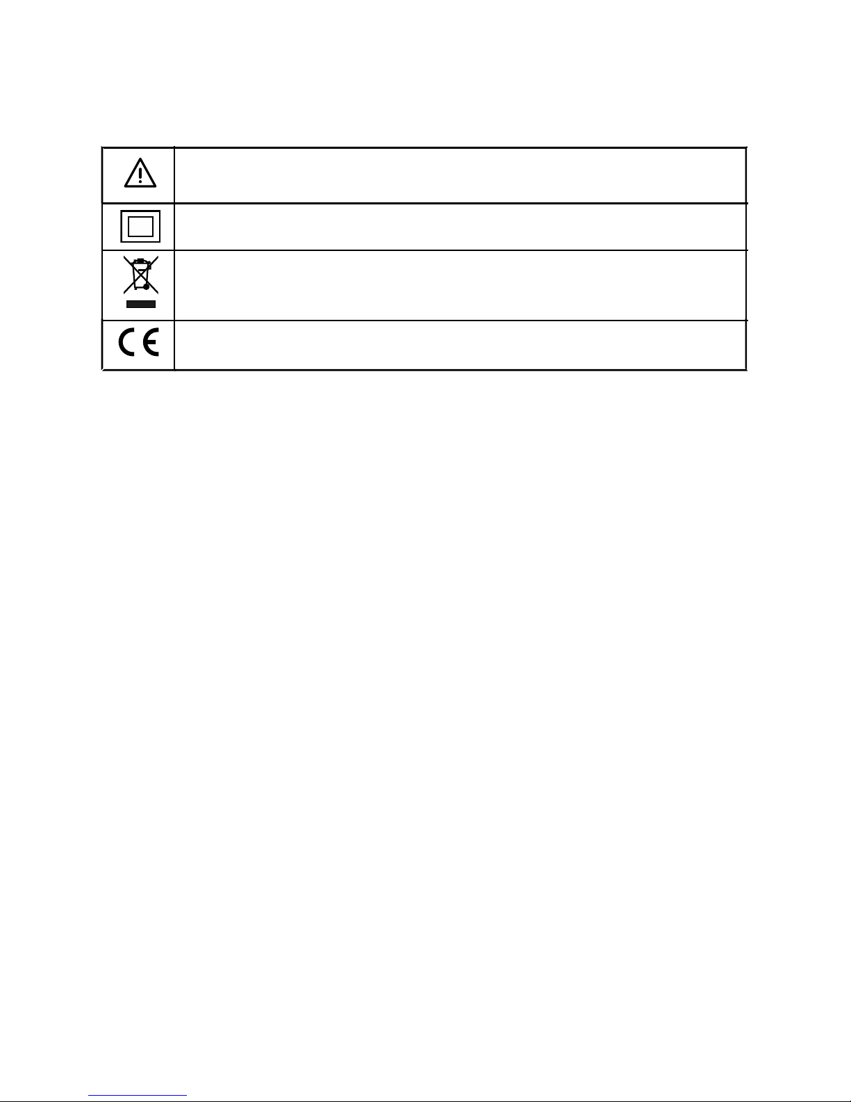
1.1 Equipment Markings
1.2 Operational Safety
The Socket & See Dead Circuit Finder is designed for use by suitably qualified
personnel familiar with electrical supply systems.
Before using your dead circuit finder please read these instructions and safety
warnings. Failure to comply with the safety warnings or use of the unit in a
manner not specified by Socket & See may result in serious injury or damage to
equipment.
Although the DCF200 is easy to use it does require the user to have sufficient
knowledge of electrical supplies to be able to identify the difference between
LIVE (energised) and DEAD (un energised) cabling.
This product is for use on dead circuits only DO NOT connect to a live supply.
2. Description
The Socket and See DCF200 is intended for use on DEAD CIRCUITS ONLY and
can be used for.
●Fuse finding - Find which MCB or Fuse is feeding the dead circuit
●Wire tracing - Trace wires through floors and walls
●Wire picking - Pick the correct wire from a bundle or loom
●Wire break detection - find an open circuit in a damaged wire
●Circuit identification - find a circuit by identifying the individual conductor
Caution - refer to the instruction manual
Construction is double insulated
Product should be recycled as electronic waste
Conforms to EU standards

3
SS0018V2
2.1 Features
Receiver
●Simple single button operation
●Auto adjustment
●Can detect up to a meter from the cable
●Audio and visual (bar graph) indication
●Auto power off to preserve battery life
Transmitter
●Battery Powered (no mains voltage required)
●Operates with or without an earth
●Protected against accidental connection to a live circuit up to 440 V
●Auto power off to preserve battery life
2.2 Indication
1
2
1 LED BAR GRAPH
Indicates the strength
of the received signal
from the transmitter .
The stronger the signal
the more LEDs are
illuminated and the
higher the pitch of the
audible beeping.
2 NO SIGNAL LED
Will be illuminated
and accompanied by
a steady beeping
tone when the
receiver is scanning
for a signal.

4
SS0018V2
3. Usage
3.1 Battery Installation and Status
Both the transmitter and receiver must be fitted with an MN1604 or equivalent
9V battery before use (not supplied).
Transmitter:
To gain access to the battery compartment remove the four screws that secure
the back of the transmitter case. Fit the battery into the rectangular bay with
the foam pad at the base of the battery. The moulding will only allow the
battery to be fitted in the correct orientation. To avoid any risk of static damage
to components please take care not to touch any of the components on the
circuit board whilst the case is open. Re-fit the back cover.
Receiver:
Unscrew the battery cover. Fit the battery and replace the cover.
3.2 Principles of operation
The transmitter injects a safe low voltage signal via the red test lead into the
cable under test. The green test is is connected to an ‘earthy' point.
The receiver picks up the encoded signal and automatically adjusts its sensitivity
to the strength of the signal being received to eliminate ‘false’ signals. The
tracing signal is indicated in the form of a variable LED bar graph with an
increasing / decreasing tone according to the strength of the signal received.
Best results will be obtained if the circuit you are tracing is not in close proximity
to live circuits. Therefore where possible make sure all circuits are DEAD (at the
Mains Switch) to concentrate the signal on the circuit you are tracing.
The user is the return signal path for the receiver so at all times keep your hold
on the receiver constant. If you change your grip on the receiver you change
the strength of the received signal so be consistent in the way you hold the
receiver during each operation. For the same reason if the signal trace is weak
it can be improved if you increase your own ‘grounding’ by touching the case
of an earthed appliance or a nearby wall with your other hand.
An important part of setting up the transmitter for use is to ensure that the green
crocodile clip is connected to as good an earth as possible. Bear in mind that if
you are trying to trace a disconnected Live or Neutral conductor in a three
core cable there is a good chance that the accompanying earth wire will also
be disconnected and will be incapable of providing the Earth needed.
To enable easy connection to a good Earth we have included with the tester
an adapter that enables you to connect the green 4mm plug directly into the

SS0018V2
5
Earth of a 13A socket. If you are using it in a location where a socket is not
available the crocodile clip can be used to connect the green lead to an
earthy’ point, such as bonded metal work or even a nail in a plaster wall.
3.3 Sensitivity and Reset Function
In use the receiver will automatically adjust its sensitivity to the maximum
strength of signal received since it was last reset. The sensitivity is reset each time
the ‘POWER ON’ button is pressed.
The indications given by the receiver are:
●SCANNING FOR SIGNAL / NO SIGNAL DETECTED: Indicated by only the ‘NO
SIGNAL’ LED being lit whilst accompanied by a steady beeping tone.
●SIGNAL DETECTED: A higher pitched tone beeping with greater frequency;
normally accompanied by one or more of the signal strength LEDs being lit.
●MAXIMUM SIGNAL DETECTED: All signal strength LEDs lit accompanied by a
continuous or rapidly beeping high pitched tone.
3.4 Cable Tracing
In ideal conditions the receiver can trace a signal over half a meter away from
the cable being traced. The effects of wood, plaster (especially if damp) or
screened plasterboard will reduce the signal. Earthed metal conduit may shield
it completely.
Once the transmitter has been turned on and connected to the conductor
under test the receiver should be turned on or reset whilst being held away from
the circuit. Slowly bring the receiver towards the circuit until it recognises the
test signal. This is normally indicated by a sudden change from a NO SIGNAL
indication to a MAXIMUM SIGNAL indication.
It is important to only bring the receiver as close as is necessary for it to
recognise the signal and to stop at this point and move the receiver away from
the circuit. You will notice that the receiver now indicates varying signal
strength as you move further from or closer to the distance at which it
recognised the signal.
The receiver will now operate at a maximum sensitivity which is ideal for cable
tracing.
Do not touch the cable that you are tracing (even the outer insulation) with
your other hand or you will effectively short out the signal you are tracing.
For the reasons mentioned above it is important to keep your grip on the
receiver consistent whilst tracing a circuit.

6
SS0018V2
If at any stage the receiver is brought into close proximity with the circuit under
test (including the red test lead) the sensitivity will adjust automatically to the
stronger signal and thereafter give a positive indication only when a similarly
strong signal is received, i.e. when it is very close to the circuit.
If this happens and you need to increase the sensitivity to continue tracing the
circuit (for instance where a cable in surface mounted conduit disappears
behind a dry lined wall) you will need to remove and reset the receiver before
repeating the signal recognition process described above.
As it is possible for the test signal to bleed into neighbouring conductors,
particularly at points of poor insulation, best results will be achieved by
grounding other neighbouring conductors where possible. If this cannot be
done it is recommended that upon having traced a cable to its remote point a
check is made to ensure that it is the required circuit and that you have not
followed an induced signal in a neighbouring cable.
You can do this by resetting the receiver and touching it onto the cable
immediately next to the red clip. This will have the effect of de-sensitising the
receiver so that it only responds to a very strong signal. Without resetting the
receiver touch the cable at the remote point and a maximum or close to
maximum strength indication should be given.
3.5 Fuse Finding
Open all breakers or remove fuses even if dead. Otherwise all circuits will have a
signal on them. If you are familiar with live circuit fuse finders the principles are
similar but it is worth experimenting with the position of the DCF200 receiver
sensor tip relative to the breaker as it is different to live circuit fuse finding.
3.6 Cable Sorting
To trace individual cables in a multi conductor bunch completely avoid
touching any other wires even the outer sheaths with your other hand as this will
effectively short out the signal you are tracing.
In any situation where there are multiple conductors optimum results will be
obtained by grounding or earthing all other conductors except the circuit under
test. IT IS ESSENTIAL TO ENSURE THAT ALL CONDUCTORS ARE DEAD BEFORE
DOING THIS.
3.7 Finding a Break in a Cable
Again avoid holding or touching the cable with your other hand. Trace the
cable slowly and at the point the signal falls off you are within about 0.5 metres
of the break (or more likely the disconnection).

7
SS0018V2
3.8 Functions
Transmitter Functions
Power on button: Short press to turn the unit on. Long press to turn the unit off.
When connecting the transmitter to a conductor check the colour of the
‘POWER ON’ LED.
GREEN: Everything is good
RED: Hazard. The leads have been connected to the mains or a
conductor with voltage on it. Remove the leads and check the
voltage with a voltage Indicator and ensure the conductor is dead
before re-testing.
ORANGE: Short circuit. The Red and Green leads are connected to the
same circuit. Remove the Green lead and attach it to Earth or
Neutral.
FLASHING: Low battery
Auto shut off after 30 minutes. Battery life of approximately 60 hours.
Receiver Functions
Short press to turn on; Short press (when in operation) to reset memory. Long
press to turn off.
Bar Graph: Peak signal tracking with bar graph
Flashing: Low battery
Beeper: Relative (peak tracked) strength is indicated .
Continuous tone = The strongest signal since reset.
Intermittent beep = weak compared with peak signal.
Absolute strength indicated by pitch (tone). Higher tone = stronger
signal.
At power up or reset the receiver waits for a signal to wake up.
Auto shut off after 3 minutes.
Self Test Put the transmitter on the bench with both wires separated. Hold the
receiver and switch on. Tracing either wire should indicate well (as they are
both giving a signal). Reset before use.

8
SS0018V2
4. Maintenance and Service
If required, clean with a damp cloth and mild detergent. Do not use abrasives
or solvents. Take care not to allow water into the unit.
Access to the protective fuse is gained through the battery compartment.
Contact Socket and See for parts and technical assistance.
Socket and See
Century Road
High Carr Business Park
Newcastle
Staffordshire, UK
ST5 7UG
Tel: +44 (0) 1782 567096
Fax: +44 (0) 1782 567095
Email: [email protected]
Website: www.socketandsee.co.uk

SS0018V2
9
Specification
Operating Voltage 9V DC
Overvoltage Category Protected against accidental mains
connection up to 440 V
Power supply Transmitter 9V 6F22 Battery
Receiver 9V 6F22 Battery
Weight 950g
Dimensions 260H x 230W x 70D (mm)

SS0018V2
Ordering Information
Item Supplier Code
Easy Fuse Finder SOC/FFCB100UKA
Easy Fuse Finder (Inc additional 2-way
lead set) SOC/FFCB200UKA
Dual Voltage Fuse Finder Kit SOC/FFCB1140UK
Dead Circuit Finder DCF200
Combined fuse and dead circuit
finder kit (FFC200/DCF200) SOC/FFCDCFKIT
Table of contents
Other Socket & See Camera Accessories manuals


