Tarot T-2D User manual

Tarot 2-AxisBrushless GimbalforGoproUserManualV1.0
1. Introduction
TarotT-2Dgimbalisdesigned forthe GoproHero3, which iswidelyused infilm,television
productions,advertising aerialphotography,etc. Using 6061T6aluminumalloyfull CNC
precision machining and brushless motordriving, itsoverall frameworkisdesigned withthe idea
ofcompact,easyinstallation, high precision, lightweight,high stabilityand manyother
characteristics.Even if the aircraft isinhigh-speed flight,it can still stabilize and controlthe
Goprocamerapreciselywiththe higheststability,sopicturesorvideosoutputcanreach the best
quality.
2. Specifications
1. Support GOPROHero3 video output.
2. Support reverse powersupplyprotection and powervoltage compensation.
3. Support motorconnectorshort circuit protection.
4. Support tilt initialangle setting.
5. Support adjustable gainsand 3Dattitude displayon PCsoftware.
6. Support stick rate mode and position mode.
7. Supported receivertype:conventional/S-BUS/DSM2/DSMJ/DSMXreceiver.
8. Supported RC:PPM/PCM/2.4G.
9. Operating supply:DC 7.4V~14.8V(Li-Po 3S isrecommended)
10. Operating current: 200mA-500mA(Depending on powersupplyvoltage and motorpower)
11. Operating temperature:-15 C~65 C.
12. CPU:Double 32bit ARM
13. Sensortechnology:3-axisMEMSgyro and accelerometer.
14. Max angularrate:2000 /sec.
15. Max acceleration:16g.
16. Controlfrequency:2000Hz
17. Motordriverfrequency:20KHz (quietand smooth)
18. Controlaccuracy:0.1
19. Controlrange:-45 ~45 (roll),-135 ~90 (tilt).
20. Attitude arithmetic:BLDC gimbaldedicated brushlessmotordecoupled EKFalgorithm.
21. Aerialphotographyequipment: GOPROHero3.
3. Connections
Connectionsinstructions
WWW.0577MX.COM

1.Powersupply
DC7.4V~14.8V(Li-Po 3S isRecommended)
2.Gimbalcontrollerconnector
ViaUSBmoduleconnected tothe computer,used toadjustthe gimbalcontrollerparameterand
statusmonitoring.
3.Motordriverconnector
ViaUSBmoduleconnectedtothe computer,used toadjustthe motordrivermodule(motor
polesand power), and voltage and currentmonitoring.
4.Receiverand camera controlconnector
R: conventionalreceiverroll channelinput
T: conventionalreceivertiltchannelinput
C: conventionalreceiverstick mode channelinput(rate mode and position mode)
S: S-BUS receiverorconventionalreceivercamera input
P: camera controlservo output(Infrared cameramodule can be connected)
+: 5Voutput
-: powerground
5.DSM2/DSMJ/DSMX
Used to connectDSM2/DSMJ/DSMXreceiver
6.Roll and tilt motorconnector
Used to connectmotor
7.Sensorconnector
Used to connectsensormodule
4.Videoline:
WWW.0577MX.COM

5. LEDindication
Y: Yellow,B: Blue,R: Red,G: Green
Yellowblink 2 times Initialization successfully
Yellowsolid Initialization notfinished, keep gimbalstatic
Blue blink Receiverconnected orPCsoftware connected(normal)
Blue LEDsolid Receivernotconnected(normal)
Red solid Angleoutofband orerroroccur
Green solid Overcurrent,Aftertroubleshooting, reapplypowercan recover
6. Protection function
Reverse powerprotection:
When thepowerisreversed, the gimbalwon’tresponseavoiding burningthe controlpanel,
therebyenhancing reliability.
Motoroutputshortcircuit protection function:
Whenthe motoroutputisshorted motoroutputPTZcontrolpanelwill turnoffandthegreen
lightislit,therebyprotectingthe controlpanelfromburning. Afterthe short troubleshooting, you
mustre-powerto liftthe protection.
Angleoverrun protection function:
When thecameraangleexceedsthe limit,it will automaticallyshutdownthe motoroutput
and the red lightislit,therebyprotecting the lineslaiddownbeing wrappedbrokeninunexpected
situations.Afterthe short troubleshooting,re-powerorre-startthe motoron the computerside,
then the gimbalcan be restored.
7. Setup instruction
Brushless gimbalsystemusesadual-processorsolution (gimbalcontrollerprocessorand
WWW.0577MX.COM

motordriverprocessor). Software interface isasfollows.
A、GimbalcontrollersoftwareUIinstructions
ConnectUSBprogrammertogimbalcontrollerport.Open ZYX-BMGC.exe, run
ZYX-BMGC software, software interface isasfollows.
(1)Open port:
SelectCOMport inthesoftware, andclick “OpenCOMPort”.Afterthat,you canpoweron
gimbal.The powersupplyshould make gimbalwork safely.
(2)Gimbalcontrollerconnection status:
Afterthe initialization process,the statusbarshouldshow “All parameters updated!”.This
meansgimbalhasbeen connected tosoftwaresuccessfully.Togglearbitraryaxisofthe gimbal,
you shouldsee the movementofthe gimbalin3Dattitude displayon the screen. Forsafe
configurations, when gimbalconnected, the programautomaticallysetsmotoroutputmode off.
(3)Sensormodule mount
You shouldselectrightsensormodulemounting wayat “SensorModuleMount”according
tostep1. Then, you shouldobserve “3DAttitude Display”whethercan reflectcamera’sreal
WWW.0577MX.COM

motion.
(4)Receivertype:
Connectyourreceiver’sconnection toZYX-GS’receiverinputport,and selectrightreceiver
type inconfiguration program.When the receivertype changed, you shouldclick “WriteSettings
toFlash”, and restart ZYX-GS.
DSM2/DSMJ/DSMXreceivertype:
DSM2-1:TransmitterisDX7 etc. (binding by6 or7 channelsreceiver)
DSM2-2:TransmitterisDX8, DSX9etc. (binding by6or7 channelsreceiver)
DSM2-3:TransmitterisDX8, DSX9etc. (binding by9channelsreceiver)
DSM2-4:TransmitterisDM8, DM9 module. (binding by6 or7 channelsreceiver)
DSMJ:TransmitterisDSMJformat. (Binding bymatched receiver)
DSMX-1:TransmitterisDX 8 etc.(11msmode, binding bymatched receiver)
DSMX-2:TransmitterisDX 8 etc.(22msmode, binding bymatched receiver)
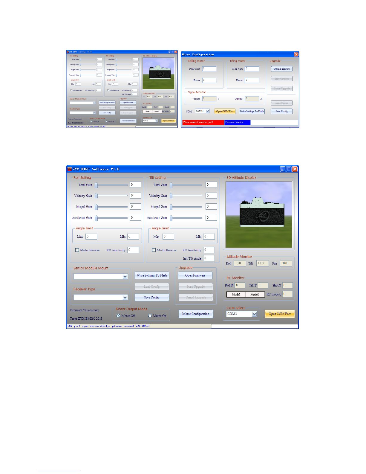
(5)RCmonitor
Afteryou selectreceivertype and restart gimbal,the windowwill giveyou arealtime
displayforall inputchannels.
R:roll inputchannel.
T:tilt inputchannel
S:camera remote infrared shuttercontrolchannel
C:RCMode Switch:
Mode1:stick rate mode
Mode2:stick position mode
(6)Angle limits
You can limit the roll angleand tilt angleforyourneed. Roll anglelimitsrange is-45 ~45 ,
tilt angle limitsrange is-135 ~90 .
NOTICE:whenthe attitude ofthe gimbalisnotinlimitsrange, gimbalwill setmotoroutput
mode offforsafety.When you configuregimbalatfirsttime, you shouldsetanglelimitswith
lowervalues.
(7)Motordirection
Motordirection isselected according to the motorrotation.
(8)Initialtilt angle
Instick ratemode, when thegimbalpoweron,the initialtilt angleisdetermined bythis
parameter.
(9)Motoroutputmode:
Motoroutputmode isused forkeeping thegimbalsafe when configuregimbal.
Motoroffmode:gimbalshutsdown motoroutputsignal.
Motoron mode:gimbaloutputsmotorsignal, atthistime, the gimbalstabilization works.
NOTICE:
(a)When the motoroutputmode is “motoroff”,you can setsensormodule mounting way.
(b)When themotoroutputmode is “motoron”,therearetwosituationsgimbalwill automatically
shutdownmotoroutputsignal.Firstsituation:the totalgainiszeroorotherthree gainsarezero
on anyaxis.Second situation:currentattitude ofthegimbalisnotin anglelimit ranges. When you
need motoroutput,you shouldsetgainsvalue non-zero, keep the gimballeveland make surethe
sensormodule mounted rightly.
WWW.0577MX.COM

(10)PIDparametersadjustment
PIDparameters range is[0-500],the basicruleisthe totalsensitivitycan notbe 0,speed
sensitivityand integration sensitivitycan notbothbe 0. If break theserulesthe gimbalwillturn
offthe motor, thiscan protectgimbaland camera.
Underthe sameload condition, if motorpowerparameterisincreased, you shouldreduce the
gimbalgains.Ifitsvalue isdecreased, you shouldincreasethe gimbalgains.Inguarantee the
motorpowerunderthecondition ofenough, you shouldminimize powervalue forlargergainsto
getbettergimbalstabilization performance. Notice thatreducing motorpowerwill affectthe
abilityofthe gimbalresisting disturbance.
Step 1.Accelerate gain:
First,setthe totalgaintoanappropriatevalue (e.g.100),setthevelocitygainandintegral
gaintothe minimumvalue(e.g. 1).Secondly,increaseaccelerategaingraduallyuntil the gimbal
shaking. Thisvalue isthe largestaccelerategain. Finally,reduce the accelerategainby20%asthe
finalgain.
Step 2. Velocity gain:
First,increasevelocitygaingraduallyuntil the gimbalshaking. Thisvalue isthelargest
velocitygain. Finally, reduce the velocitygain by20%asthe finalgain.
Step 3. Integralgain:
First,increaseintegralgaingraduallyuntil the gimbalshaking. Thisvalue isthe largest
integralgain. Finally, reduce the integralgain by20%asthe finalgain.
Step 4. Fine-tune gains:
Aftercompleting the above steps, we can be appropriate to fine-tune each gainsand getbetter
result.
(11)Write settingsto flash
Afteryourconfiguration finished, click ”WriteSettingsToFlash”.When you writeflash
successfully,the settingsaresaved ingimbal.Nexttime, when you restart gimbal,thesesettings
are loaded automatically.
B. Gimbal motordriversoftwareUIinstructions
ConnectUSBprogrammertomotordriverport.OpenZYX-BMGC.exe;runZYX-BMGC
software, click ‘motorconfiguration’,the interface ofmotorconfiguration isinthe following
figure.
WWW.0577MX.COM

(1)Open COM port:
SelectCOMport inthe motorconfiguration,andclick ‘OpenCOMPort’.Afterthat,you can
poweron the gimbal.The powersupplyshouldmake the gimbalwork safely.
(2)Motordrivermodule connection status:
Aftermotordrivermoduleinitialization process,the statusbarshouldshow “All parameters
updated!”.Thismeansmotordrivermodule hasbeen connected to software successfully.
(3)Polarnum:
Polarnumismotormagneticpolenumber; thisparameterwillaffectthe reduction ratioand
highestspeedofthemotor.Usually,itsvalue shouldbesettothe actualnumberofthe motor.If
you needspecialperformance, itsvalue canbesettodifferentfromthe actualpolenumberofthe
motor.
(4)Motorpower:
The range ofmotorpoweris0%-100%,itsvalue can be adjustaccording toload. Underthe
sameload condition, ifmotorpowerparameterisincreased, you shouldreduce the gimbalgains.
Ifitsvalue isdecreased, you should increase the gimbalgains. In guarantee the motorpowerunder
the condition ofenough, you shouldminimize powervalue forlargergainstogetbettergimbal
stabilization performance. Notice thatreducingmotorpowerwill affectthe abilityofthe gimbal
resisting disturbance.
(5)Signalmonitor:
Displaysupplyvoltage and operating currentofthe gimbal.Voltage value displayed will be
smallerthan the powersupplyvoltage of0.3Vorso.
(6)Write settingsto flash:
Afteryourmotorconfiguration finished, click”Write Settingsto Flash”. When you write flash
successfully,the settingsaresaved ingimbal.Nexttime,when you restart it,thesesettingsare
loaded automatically.
8. Upgradefirmware
WWW.0577MX.COM

Notice:BecausethisgimbalcontrolleradoptsdoubleCPUsolution, asmaincontrollerCPU
and motordriving CPU,therearedifferentupgradefirmwarefilesfortheseCPUs.Before
upgradingfirmware, you shouldmake surethehardwareinterface connectedrightlyand choosing
correspondingfirmware files.
1. Main controllerfirmware upgrade:
Firstly,you shouldconnectUSBprogrammertomaincontrollerport,and selectrightCOM
port,click “Open Firmware”,choosethe firmwarefileyou wanttoupgrade(do notclick”Open
COMPort”).Afterthat,click “Start Upgrade”,and then,poweron the gimbal.Whenthe progress
barfinished, firmwareupgradessuccessfully.Afterfirmwareupgradesfinished, you can open
COMport toconnectgimbaltoconfiguration program.The newmaincontrollerfirmwareversion
can be seen in the window.
2. Motordriverfirmwareupgrade:
Firstly,you shouldconnectUSBprogrammertomotordriverport,andclick ‘motor
configuration’toenterintothe interface ofmotorconfiguration. SelectrightCOMport,click
“OpenFirmware”,choosesthe firmwarefileyou wanttoupgrade (do notclick”Open COM
Port”).Afterthat,click “Start Upgrade”,and then, poweron the gimbal.When the progress bar
finished, firmwareupgradessuccessfully.Afterfirmwareupgrade finished, you canopen COM
port toconnectgimbaltoconfiguration program.The newmotordriverfirmwareversion can be
seen in the window.
WWW.0577MX.COM
Table of contents
Other Tarot Camera Accessories manuals
Popular Camera Accessories manuals by other brands

AMPHIBICO
AMPHIBICO Video Camera Housing instruction manual

Bioenno Power
Bioenno Power BLF-2410A quick start guide

Savage
Savage Ringlight Beauty Video Kit SETUP & USAGE

Power works
Power works P24B2 Operator's manual

Ikelite
Ikelite Nikon L2 instruction manual

Panasonic
Panasonic HFS1442A operating instructions