manuals.online logo
Brands
  1. Home
  2. •
  3. Brands
  4. •
  5. Manfrotto
  6. •
  7. Camera Accessories
  8. •
  9. Manfrotto 115 User manual

Manfrotto 115 User manual

J
E
I
INTRODUCCION
Rótula fotográfica 3D ideal para cámaras hasta el medio formato.
CARACTERISTICAS PRINCIPALES:
• Gran plato portacámara
• Grandes y cómodas manetas de trinquete
• Movimientos versátiles
PREPARACION
ACOPLANDO LA ROTULA AL TRIPODE
Acople la rótula al trípode utilizando la rosca “E” de 3/8” hembra.
Las plataformas superiores de los trípodes Manfrotto vienen con tres tornillos
“F” que presionan contra la base de la rótula para afianzar un bloqueo seguro.
ACOPLAR LA CAMARA A LA ROTULA Y
La palanca en los botones de trinquete “B” (fig. 1) y “C” puede reponerse según
necesidad sin efectuar el bloqueo en si. Sencillamente tirar de la palanca hacia
fuera, girarla lo necesario y soltar de nuevo la palanca que vuelve
automaticamente a la posición ajustada.
Fije el cámara sobre la base “G” (fig. 2) enroscando el tornillo “M” en la rosca
de la cámara SIN EMPLEAR EXCESIVA FUERZA (recuerde que debe
desenroscar primero el anillo “Q” por completo)
El tornillo “M” se desliza por la ranura “H” (fig. 1)
Antes de apretar(bloquear) del todo alinear el objetivo del cámara con la
base “G”(fig. 3) y escoger la mejor posición de equilibrio.
Para una seguridad adicional asegúrese que el anillo “Q” esté apretado
contra la base “G”. El anillo “Q” (fig. 4) viene con la ranura “S” para
facilitar el apretarlo (por ej. con un destornillador).
QUITAR LA CAMARA DE LA ROTULA
Siempre que haya que retirar la cámara de la rótula SUJETE LA CAMARA
FIRMEMENTE EN UNA MANO mientras esté aflojando el tornillo “M” habiendo
soltado primero el anillo “Q”.
USO
El mando “A” y las dos manetas “B” y “C” controlan el movimiento panorámico,
nivelado lateral y la inclinación vertical resp.
El Mando “A” afloja y bloquea el giro de 360°
La maneta “B” afloja y bloquea el movimiento del nivelado lateral entre
+180° y -30°
La maneta “C” afloja y bloquea la inclinación vertical entre +180° y -30°.
Cuando afloja el mando/maneta de control para permitir el libre movimiento de
la rótula hasta la posición deseada SUJETE SIEMPRE LA CAMARA CON UNA
MANO utilizando la otra para realizar los ajustes.
Una vez conseguidos bloquee la posición apretando el mando/maneta.
INTRODUZIONE
Testa fotografica 3D ideale per fotocamere 35mm e medio formato
CARATTERISTICHE
• Grande base d’appoggio per fotocamera
• Comode leve a ripresa
• Grande versatilità nei movimenti
PREPARAZIONE
MONTAGGIO DELLA TESTA SUL TREPPIEDE
Montare la testa sul treppiede utilizzando l’attacco femmina “E” da 3/8” (fig. 1).
I treppiedi Manfrotto sono dotati di tre grani “F” da avvitare contro la base della
testa per un bloccaggio efficace e sicuro.
MONTAGGIO DELLA CAMERA SULLA TESTA E
La posizione delle leve a ripresa “B” e “C” (fig. 1) può essere variata in qualsiasi
momento per maggior comodità di presa e utilizzo: tirare la leva verso
l’esterno, effettuare la rotazione voluta e rilasciare la leva, la quale rientrerà
automaticamente nella sede.
Per fissare la fotocamera alla piastra “G” (fig. 2) avvitare, SENZA FORZARE, la
vite d’attacco “M” nel foro filettato della fotocamera fino a fondo del filetto
(ricordasi prima di svitare completamente la ghiera “Q”).
La vite d’attacco “M” corre lungo la feritoia “H” (fig. 1)
Prima del bloccaggio definitivo, allineare l’obiettivo della fotocamera alla
piastra “G” (fig.3) e scegliere la posizione che consente il miglior
bilanciamento
Bloccare definitivamente la fotocamera avvitando la ghiera “Q” contro la
piastra “G”. La ghiera “Q” (fig. 4) è provvista di sede “S” per facilitare (ad
esempio con un cacciavite) il serraggio più efficace.
SMONTAGGIO DELLA FOTOCAMERA DALLA TESTA
Ogni volta che è necessario togliere la fotocamera dalla testa tenere
saldamente con una mano la fotocamera e con l’altra svitare la vite “M” dopo
aver allentato la ghiera “Q” (fig. 5).
USO
I movimenti della testa sono bloccati dalla manopola “A” e dalle leve “B” e “C”
(fig.1)
La manopola “A” blocca il movimento panoramico a 360°
La leva “B” blocca il movimento di livellamento laterale tra +180° e -30°
La leva “C” blocca il movimento d’inclinazione verticale tra +180° e -30°
Tenendo saldamente la fotocamera con una mano, svitare la leva fino a liberare
il movimento relativo.
Raggiunta la posizione voluta avvitare la leva fino ad ottenere un bloccaggio
efficace.
Cod. 115,03 - 09/04 Copyright © 2004 Manfrotto Bassano Italy 10 cm 0,6 kg 5 kg
4” 1,32 lbs 11 lbs
INSTRUCTIONS
115 - USA 3028
1
1 2 3 4
5
1
1
1 2 3 4
5
1
1
2 3 4
5
1
GB FD
INTRODUCTION
Rotule photographique 3D, idéale pour les appareils allant jusqu’au moyen
format.
CARACTERISTIQUES
• Plateforme large
• Poignées à cliquet plus faciles à saisir
• Mouvements multi-directionnels
MONTAGE
MONTAGE DE LA ROTULE SUR LE TREPIED
Vissez la rotule par le filetage femelle 3/8” “E” sur le trépied.
Le socle de la colonne centrale des trépieds Manfrotto est équipé de 3 vis sans
tête “F” qui viennent en butée sur la base du support afin d’assurer un blocage
parfait.
MONTAGE DE L’APPAREIL SUR LA ROTULE ET
Les leviers à cliquet “B” (fig. 1) et “C” peuvent être mis dans n’importe quelle
position sans pour cela les bloqués. Il suffit simplement de les tirer vers
l’extérieur et de les tourner jusqu’à la position souhaitée, puis de les relâcher.
Ils se placent automatiquement dans la bonne position.
Fixez l’appareil sur la base “G” (fig. 2) en vissant la vis “M” dans le trou
fileté SANS FORCER (n’oubliez pas tout d’abord de dévisser
complètement l’écrou “Q”).
La vis “M” coulisse le long de la rainure “H” (fig. 1).
Avant de bloquer l’appareil, aligner parfaitement l’objectif sur la base “G”
(fig. 3) en équilibrant l’ensemble.
Pour plus de sécurité, vissez l’écrou “Q” jusqu’à ce qu’il vienne en butée
sur la base “G”.
L’écrou “Q” (fig. 4) a une fente “S” pour faciliter le serrage (à l’aide d’un
tournevis).
DEMONTAGE DE L’APPAREIL DE LA ROTULE
Si vous devez démonter votre appareil, MAINTENEZ LE PARFAITEMENT
D’UNE MAIN pendant que vous desserrez la vis “M” en ayant préalablement
dévissé l’écrou “Q”.
UTILISATION
Le bouton “A” et les deux poignées “B” et “C” permettent respectivement de
contrôler le mouvement panoramique, latéral et vertical.
Bouton “A” libère et bloque le mouvement panoraique à 360°
Poignée “B” libère et bloque le mouvement latéral de 180° à -30°
Poignée “C” libère et bloque le mouvement vertical de 180° à -30°
Afin de modifier la position de la rotule, libérez le bouton/poignées TOUT EN
MAINTENANT L’APPAREIL D’UNE MAIN pendant que de l’autre vous effectuez
le réglage.
Le blocage se fait en serrant le bouton/poignées
INTRODUCTION
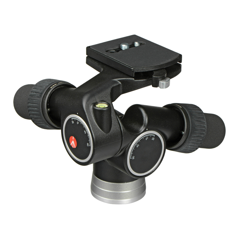
Photographic 3D head ideal for cameras up to medium format.
KEY FEATURES
• Large camera mounting platform
• Large easy grip ratchet handles
• Versatility of movements
SET UP
ASSEMBLING HEAD ON TRIPOD
Assemble the head on the tripod using 3/8” female thread “E”.
The top plate on Manfrotto tripods are equipped with three set screws “F”
which clamp against the base of the head to ensure effective and secure
locking.
ASSEMBLING CAMERA ON HEAD &
The lever on the ratchet knobs “B” (fig. 1) and “C” can be repositioned as
required without effecting the lock itself. Simply pull the lever outward, rotate as
desired and release the lever and it will automatically locate in the adjusted
position.
Fix the camera onto base “G” (fig. 2) by screwing home the camera screw “M”
into the camera’s threaded hole WITHOUT APPLYING EXCESSIVE FORCE
(remember to unscrew locking ring “Q” completely first).
The screw “M” slides long the slit “H” (fig.1).
Before fully locking, align the camera lens with the base “G” (fig.3) and
choose the best balance position.
For added security, ensure locking ring “Q” is tightened against base “G”.
Locking ring “Q” (fig. 4) is equipped with slot “S” to facilitate tightening
(with a screwdriver for instance).
REMOVE THE CAMERA FROM THE HEAD
Whenever the camera needs to be removed from the head, HOLD THE
CAMERA SECURELY IN ONE HAND whilst releasing the screw “M”, Having first
loosened the ring “Q”.
USE
The knob “A” and the two control handles “B” and “C” control the pan , lateral
levelling and vertical tilting movements respectively.
Knob “A” releases and locks the 360° panning movement
Handle “B” release and locks the lateral levelling movement between
+180° and -30°
Handle “C” release and locks the vertical tilting movement between +180°
and -30°
When releasing the control knob/handles to allow the head to be moved to the
position required ALWAYS HOLD THE CAMERA WITH ONE HAND using the
other hand to make the adjustments. When adjusted lock in position by
tightening the knob/handles.
M
G
BEA
H
C
F
Q
G
M
Q
S
G
G
G
Q
Q
M
EINFÜHRUNG
3D Fotoneigekopf für 35mm- und Mittelformatkameras.
AUSSTATTUNGSMERKMALE
• Grosse Kameraauflage
• Grosszügige Blockierhebel mit Leerlauf-Funktion
• Grosse Verstellwege
AUFSTELLEN
BEFESTIGUNG DES KOPFES AUF DEM STATIV
Schrauben Sie den Kopf mit dem weiblichen Gewinde “E” (3/8”) auf das Stativ.
Die Kopfauflageplatte von Manfrotto Stativen ist mit den Blockierschrauben “F”
ausgerüstet, welche ein unerwünschtes Losdrehen des Kopfes verhindern,
wenn sie korrekt angezogen sind.
FIXIEREN DER KAMERA AUF DEM NEIGEKOPF UND
Setzen Sie die Kamera auf die Plattform "G" (fig. 2) und drehen Sie die
Kameraschraube "M" in das Gewinde auf der Unterseite der Kamera (LOCKER
UND OHNE KRAFTANWENDUNG). Achten Sie darauf, dass Sie die
Arretierschraube "Q" vorher lösen.
Die Schraube "M" kann in der Führung "H" bewegt werden (fig. 1). Richten Sie
die Kamera vor der endgültigen Arretierung nochmals auf die Plattform "G" (fig.
3) aus und suchen Sie die beste Balance.
Um die Kamera sicher zu positionieren, muss die Arretierschraube "Q"
gegen die Unterseite der Plattform "G" gedreht werden (ggf. mit einem
Schraubenzieher). Die Schraube “Q” ist mit einer Aussparung “ S”
ausgestattet, welche es erlaubt, mit geringem Kraftaufwand eine optimale
Arretierung zu erhalten.
ENTFERNEN DER KAMERA VOM NEIGEKOPF
Halten Sie die Kamera während des ganzen Vorgangs mit EINER HAND
FEST. Lösen Sie die Schraube "Q" und danach die Kameraschraube "M",
bis die Kamera entfernt werden kann.
GEBRAUCH
Die Flügelschraube "A" sowie die Hebel "B" und "C" dienen zur Blockierung
der einzelnen Bewegungen (Panorama, Neigung seitlich, Neigung vor- und
rückwärts).
Die Schraube "A" blockiert die Panoramabewegung (360°).
Der Hebel "B" arretiert die seitliche Kippbewegung (+180° bis -30°).
Der Hebel "C" kontrolliert die Neigebewegung nach vorne (+180° bis -30).
HINWEIS:
Die Griffe der Blockierhebel “B” (fig. 1) und “C” können in der Position
verändert werden, ohne die Blockierung zu lösen. Ziehen dazu einfach den
Griff heraus und drehen ihn in die gewünschte Position. Wird der Hebel nun
losgelassen, so springt er automatisch in die korrekte Stellung.
Um ein Abkippen der Kamera zu vermeiden, müssen Sie diese unbedingt
immer mit einer Hand festhalten, wenn Sie eine Verstellung lösen. Lassen Sie
die Kamera erst wieder los, wenn die korrekte Position gefunden und die
Neigebewegung blockiert ist.
1
1 2 3 4
5
1
1
1 2 3 4
5
1
1
1 2 3 4
5
1
1
2
3
4
5
Other Manfrotto Camera Accessories manuals

Manfrotto MBOOMCFVR-S User manual

Manfrotto

Manfrotto MBOOMCFVR-S User manual

Manfrotto 405 User manual

Manfrotto

Manfrotto 405 User manual

Manfrotto MVMFXPRO2W User manual

Manfrotto

Manfrotto MVMFXPRO2W User manual

Manfrotto MKCOMPACTACN-BK User manual

Manfrotto

Manfrotto MKCOMPACTACN-BK User manual

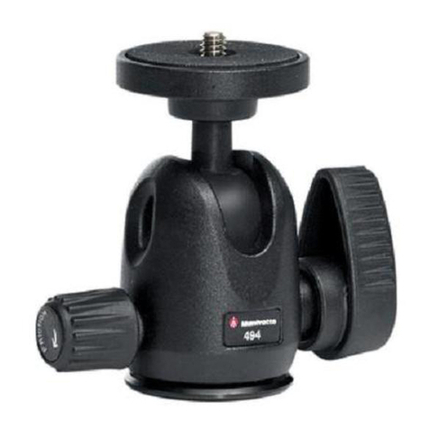
Manfrotto 494 User manual

Manfrotto

Manfrotto 494 User manual

Manfrotto 384 User manual

Manfrotto

Manfrotto 384 User manual

Manfrotto MVM500A User manual

Manfrotto

Manfrotto MVM500A User manual

Manfrotto MKBFR1A4B-BH User manual

Manfrotto

Manfrotto MKBFR1A4B-BH User manual

Manfrotto MVH608AH User manual

Manfrotto

Manfrotto MVH608AH User manual

Manfrotto 330B User manual

Manfrotto

Manfrotto 330B User manual

Manfrotto 523 PRO User manual

Manfrotto

Manfrotto 523 PRO User manual

Manfrotto 269HDB-3U User manual

Manfrotto

Manfrotto 269HDB-3U User manual

Manfrotto MVG220 User manual

Manfrotto

Manfrotto MVG220 User manual

Manfrotto 083NW User manual

Manfrotto

Manfrotto 083NW User manual

Manfrotto MVM450A User manual

Manfrotto

Manfrotto MVM450A User manual

Manfrotto MVG220 User manual

Manfrotto

Manfrotto MVG220 User manual

Manfrotto Lastolite Ezybalance User manual

Manfrotto

Manfrotto Lastolite Ezybalance User manual

Manfrotto 484 User manual

Manfrotto

Manfrotto 484 User manual

Manfrotto 535 User manual

Manfrotto

Manfrotto 535 User manual

Manfrotto 482LCD User manual

Manfrotto

Manfrotto 482LCD User manual

Manfrotto 804RC2 User manual

Manfrotto

Manfrotto 804RC2 User manual

Manfrotto 458B User manual

Manfrotto

Manfrotto 458B User manual

Manfrotto Imagine More MKC3-H01 User manual

Manfrotto

Manfrotto Imagine More MKC3-H01 User manual

Manfrotto 438 User manual

Manfrotto

Manfrotto 438 User manual

Popular Camera Accessories manuals by other brands

Really Right Stuff MACRO 150 quick start guide

Really Right Stuff

Really Right Stuff MACRO 150 quick start guide

Acebil P-35GX Operation manual

Acebil

Acebil P-35GX Operation manual

Sony HDCA-702 Specifications

Sony

Sony HDCA-702 Specifications

Visceral Psyche Films LUT Athena III Setup guide

Visceral Psyche Films

Visceral Psyche Films LUT Athena III Setup guide

Minolta MOTOR DRIVE 1 owner's manual

Minolta

Minolta MOTOR DRIVE 1 owner's manual

Fusion Sport SmartCapture NEXT user manual

Fusion Sport

Fusion Sport SmartCapture NEXT user manual

Cartoni C20S User Manual/Maintenance

Cartoni

Cartoni C20S User Manual/Maintenance

Sony VCT-D680RM operating instructions

Sony

Sony VCT-D680RM operating instructions

Flycam FLCM-RK instruction manual

Flycam

Flycam FLCM-RK instruction manual

Victron energy OPzS operating instructions

Victron energy

Victron energy OPzS operating instructions

RRS LC-A10 quick start guide

RRS

RRS LC-A10 quick start guide

GreenWorks 29462 Operator's manual

GreenWorks

GreenWorks 29462 Operator's manual

Nikon DS-U3 instructions

Nikon

Nikon DS-U3 instructions

Gardena 8835 operating instructions

Gardena

Gardena 8835 operating instructions

Really Right Stuff TQC-14 user manual

Really Right Stuff

Really Right Stuff TQC-14 user manual

SimpliPhi AmpliPhi-3-8-48 Integration guide

SimpliPhi

SimpliPhi AmpliPhi-3-8-48 Integration guide

Mint FLASH BAR 2 quick start guide

Mint

Mint FLASH BAR 2 quick start guide

Hitachi HDF-EL800H operating instructions

Hitachi

Hitachi HDF-EL800H operating instructions

manuals.online logo
manuals.online logoBrands
  • About & Mission
  • Contact us
  • Privacy Policy
  • Terms and Conditions

Copyright 2025 Manuals.Online. All Rights Reserved.