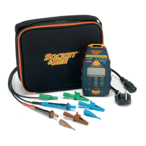
Socket & See DL 420 Plus User manual

1
SS002V2
Instruction Manual & Specification
DL 420 Plus
17th Edition Loop Testing Kit
Issue Sn

2
SS002V2
1. Safety
1.1 Equipment Markings
1.2 Operational Safety
The DL420Plus is designed to be used by skilled persons in accordance with safe
methods of work. If the DL420Plus is used in a manner not specified by Socket
and See, the protection provided by it may be impaired.
Inspect the product before using. If any damage is visible; such as cracks in the
casing, damage to any accessories, leads or probes, the unit should not be
used.
Although fully protected up to 600V AC, this tester is is for use on 230V AC 50Hz
circuits only.
This tester has been designed to be used with suitable PPE, including insulated
gloves in required.
Caution - refer to the instruction manual
Construction is double insulated
Product should be recycled as electronic waste
Conforms to EU standards
Measurement Category III is applicable to test and measuring circuits
connected after the source of the building’s low-voltage MAINS
installation. This part of the installation is expected to have a
minimum of two levels of over-current protective devices between
the transformer and connecting points of the measuring circuit.
Examples of CAT III are measurements on devices installed after the
main fuse or circuit breaker fixed within the building installation. Such
as junction boxes, switches and socket outlets.
CAT

3
SS002V2
To maintain safety always check the tester on a known correctly wired live
socket outlet before and after use. Or use a suitable checkbox such as the
Socket and See CB400.
Note. The DL420Plus uses an intelligent loop test system that suppresses sudden
changes in value (such as voltage spikes). This means that when checking the
tester on a check box the unit should be switched off between changing
impedance values.
2. Description
The DL420Plus is a multi function 17th edition tester.
2.1 Features
●Quick and convenient non trip True loop impedance test
●High current True loop impedance for greater accuracy
●Mains voltage indication
●Incoming mains polarity test
●Calculated Prospective Fault Current (PFC)
●Socket wiring tester
●Clear and simple LCD display
●Carrying case included
●IECP UKA lead. (IEC 13A plug) connecting lead
●ITLS 400. Three pole fused test leads that terminate with prods or crocodile
clips
2.2 Indication
1 2 3 4
5
6
7
8
9
10
11
12

4
SS002V2
1. Loop test function selected
2. PFC - PSC (prospective fault current - prospective short circuit current
selected)
3. Loop test mode selected - no trip (default setting) or Hi-I (high current)
4. HANDSFREE operation
5. Ohms symbol
6. Volts (AC)
7. Voltage measurement function L-N (default setting) L-E and N-E
8. Fault current
9. Battery status (shown in good condition)
10. Greater than (>) less than (<) indication
11. Tester has gone over its operating temperature
12. Wait, result calculation in progress
3. Usage
FRONT ON IMAGE REQD FOR
LABELLING

5
SS002V2
3.1 Battery Installation
Unit requires 4 x AA batteries.
Ensure that all test leads are removed before installing batteries. Remove the
battery cover on the reverse of the unit. Install the new batteries ensuring
correct polarity as indicated. After installing batteries and before use switch on
the unit and check for correct operation.
3.2 Operation
Power ON/OFF. Pressing and releasing this button turns the DL420 on. Holding
the button down for longer than two seconds turns the unit off. An auto power
off feature is also incorporated to preserve battery life.
3.2.1 Socket Test
When the DL420 is first connected to a live socket it will automatically test the
socket wiring to confirm correct installation of the socket. If three GREEN LED’s
illuminate and no sound is emitted the socket wiring is correct and you may
proceed to the incoming supply polarity test, (step 3.2.2).
A fault with the socket wiring will be indicated by an audible alternating tone
and flashing LED’s , at least one of which will be red or orange. If a fault
indication is given DO NOT PROCEED! Investigation and remedial action is
required before any further tests can be carried out.
If a fault is indicated place your thumb on the Polarity Test Pad. This will initiate
the “fault location” function. With your thumb firmly on the pad check the
indication given by the LED’s against the chart in the rear of this manual. This will
diagnose the fault condition. Note: The colour of the LED’s may change when
the pad is touched.
3.2.2 Incoming Supply Polarity Test
With all three LED’s illuminated green place your thumb on the orange polarity
test pad. If the incoming supply polarity is correct there will be no change in
indication and you can proceed to mains voltage checks, (step 3.2.3).
If the supply polarity has been reversed the three LED’s will turn RED and flash. If
this happens stop testing immediately and notify the supply company.
For further information on incoming supply polarity refer to the technical
document on the Socket and See website.

6
SS002V2
3.2.3 Mains Voltage Test
The mains AC voltage will be displayed automatically on the main LCD screen.
Check that the voltage is within the correct range 207 - 253 VAC.
The indicated voltage can be toggled between L-N (default), L-E and N-E by
using the voltage button.
Note: All tests are inhibited until the mains voltage appears in the display.
3.2.4 No Trip Loop Testing
This is the default setting for the DL420. This mode is most useful for testing either
at socket outlets, luminaires, or wiring terminals in installations where the circuit
under test is protected by an RCD.
No trip mode testing can be used with the IECP UKA lead when testing at 13A
sockets, or the ITLS 400 at all other points in the circuit. When using the ITLS test
leads the three coloured prods / clips should be connected to the
corresponding live, neutral and earth terminals.
A brief press of the test button will initiate the loop test, after a few seconds the
result will be displayed.
The no trip loop testing mode is a low current measurement technique and is
ideal for use on end circuits. However, low current measurements are more
susceptible to being effected by external factors such as contact resistance or
circuit noise. For this reason we recommend that multiple measurements are
taken and any isolated erroneous results are disregarded. The tester or the
supply should be powered off between consecutive tests.
For safety reasons no trip mode is recommended for all measurements on TT
systems.
3.2.5 No Trip PFC
Once the no trip loop test is complete pressing this button will calculate the
Prospective Fault Current (PFC) . The tester does this by dividing the L - N
voltage by the measured loop impedance.
3.2.6 High Current True Loop Impedance Testing
This is selected by pressing the Ze/DB button and can only be used with the ITLS
400 test leads in two lead mode. This is done by removing the prod of the blue
fuse holder and plugging the exposed 4mm connector into the back of the
green 4mm plug as shown below. Earth and neutral will now be connected and
ready to connect onto the earth conductor to be tested.

7
SS002V2
using the voltage button.
As the true loop impedance test is a high current measurement it is more
accurate than the No trip loop test. It is recommended when measuring (Ze) at
the supply side of distribution boards and swithgear on non TT systems.
A brief press of the test button will initiate the loop test, after a few seconds the
result will be displayed.
3.2.7 PFC
Once the true loop test is complete pressing the PFC button will calculate the
Prospective Fault Current (PFC) . The tester does this by dividing the L - N
voltage by the measured true loop impedance.
3.2.8 Handsfree Function
The DL420 has a handsfree function that can be particularly useful when testing
and holding test probes. The function is activated by holding down the test
button for two seconds.
Handsfree in No Trip Mode:
The tester will automatically conduct the socket wiring test upon connection of
the live supply. If all is well it will immediately initiate a loop test. Once the test is
complete the result will be displayed for a few seconds before the display
reverts to the L-N voltage. The loop test result can be recalled by pressing the
No Trip button.
When using handsfree mode with the ITLS 400 test leads, always connect the
earth and neutral poles before the live. Otherwise a polarity fault will be
indicated and further testing will be inhibited.
Handsfree in High Current Loop Testing Mode:The tester will automatically
conduct a loop test upon connection to the live supply and display the result.
The supply voltage can be recalled by pressing the voltage button.
For any further information on Earth fault loop testing, earthing arrangements
and supply polarity refer to the Socket and See website.

8
SS002V2
LED’s will flash to indicate a fault.
NC = No connection
Condition
Number
Wiring
Conditions Supply Terminal LED Buzzer
N E L
Socket Wiring
1 Correct N E L None
2 L-E reverse N L E Warble
3L-N-E
miswire E L N Warble
4 L-N reverse L E N Warble
5L-N-E
miswire L N E Warble
6Faulty N/L-E
miswire NC L N Warble
7Faulty N/E
miswire NC N L Warble
8 Faulty N NC E L Warble
9Faulty N/L-E
reverse NC L E Warble
10 Faulty E/L-N
reverse L NC N Warble
11 Faulty E N NC L Warble
12 Faulty E/N
miswire E NC L Warble
13 Faulty E/L-N
miswire L NC E Warble
14 Faulty L/N-E
miswire L N NC Warble
15 Faulty L/E
miswire N L NC Warble
16 Faulty L/N-E
miswire E L NC Warble
17 Faulty L/N
miswire L E NC Warble
18 No mains NC NC NC None

SS002V2
9
4. Maintenance and Service
If required, clean with a damp cloth and mild detergent. Do not use abrasives
or solvents.
There are no user serviceable parts.
Contact Socket and See for parts and technical assistance.
Socket and See
Century Road
High Carr Business Park
Newcastle
Staffordshire, UK
ST5 7UG
Tel: +44 (0) 1782 567096
Fax: +44 (0) 1782 567095
Email: [email protected]
Website: www.socketandsee.co.uk

Specification
Wiring Test
Detects missing E or N (>15kΩ)
Detects L-E or L-N swap
Detects Network Supply Live - Earth/Neutral reversal by use of Polarity Test Pad.
Phase - Neutral voltage measurement +1% + 1V AC
Phase - Earth voltage measurement +1% + 1V AC
Neutral - Earth voltage measurement +1% + 1V AC
Loop Test
(No trip mode, 3 wire testing, Phase - Neutral - Earth all connected)
Test current <15mA at 253V AC
Range Accuracy
0.00 to 9.99 Ω + 5% + 5 digits
10.00 to 99.9 Ω + 3% + 3 digits
100.00 to 500 Ω + 3% + 3 digits
(High current mode 2 wire testing Phase - Neutral or Phase - Earth connected
using true impedance measurement
Range Accuracy
0.00 to 9.99 Ω + 3% + 3 digits
PFC Measurement
10A - 19.9kA
This is calculated using the loop test
measurement but will be inherently
more accurate than traditional
methods as the test is of impedance
not solely resistance.
10
SS002V2

11
SS002V2
Specification Continued
Overvoltage Category CAT III 300 V
Over Voltage Protection 440V AC No damage complete
recovery
Operating Temperature 0ºC to 40ºC
Operating Humidity 80% @ 31ºC to 50% @ 40ºC
Safety Compliance BS EN 61010-2-030:2010
Probes GS38 Compliant
Dimensions 157mm x 89mm x 39mm
Weight 400g

SS002V2
12
Ordering Information
17th Edition Equipment
Item Supplier Code
Socket and See PDIT360 Part P
insulation tester
SOC/PDIT360
Socket and See CB400 Professional
non trip check box
SOC/CB400
Socket and See PDL310 4 in 1 Loop
tester
SOC/PDL310
Socket and See DL420Plus Loop
testing kit
SOC/DL420Plus
Socket and See PDL234Plus Part P
Loop testing kit
SOC/PDL234Plus
Socket and See DRC430 Full Function
RCD Tester
SOC/DRC430
Socket and See fused test leads SOC/ITLS400
Table of contents
Other Socket & See Measuring Instrument manuals
