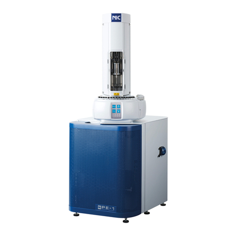
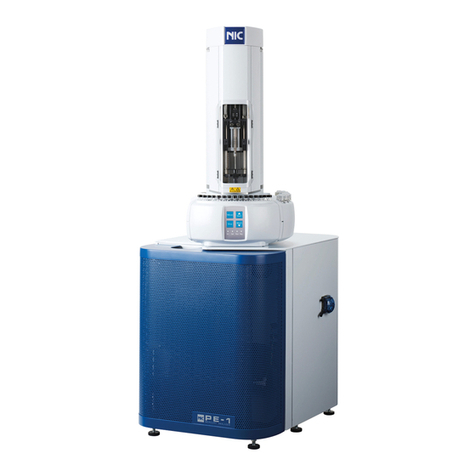
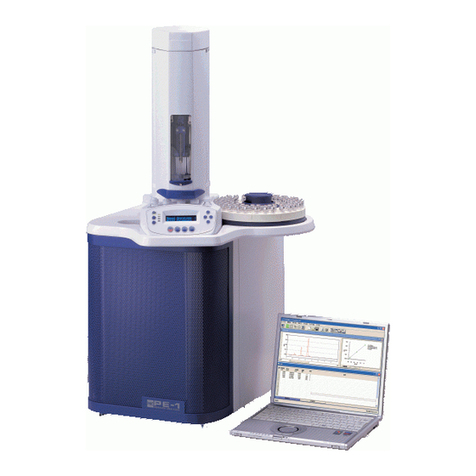
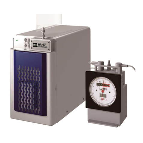
Nic PE-1 User manual

Automatic Petro Pyrolysis Mercury
Analyzer
PE-1
PE-1000
Instruction Manual
NIC-600-2266-03
Nippon Instruments Corporation

NIC-600-2266-03
Table of Contents
2
Automatic Petro Pyrolysis Mercury Analyzer
PE-1000 Instruction Manual
Table of Contents
1. READ FIRST! .....................................................................................................................7
1.1 SAFETY PRECAUTIONS.....................................................................................................7
1.1.1 Safety symbols .......................................................................................................7
1.1.2 Installation precautions...........................................................................................7
1.1.3 Maintenance precautions .......................................................................................7
1.2ABOUT THE PE-1000.......................................................................................................8
2. SPECIFICATIONS..............................................................................................................9
2.1 STANDARD CONFIGURATION .............................................................................................9
2.2 UNIT SPECIFICATIONS ......................................................................................................9
3. EQUIPMENT OVERVIEW................................................................................................10
3.1 MEASUREMENT PRINCIPLE .............................................................................................10
3.2NAMES OF PARTS...........................................................................................................11
3.2.1 PE-1 (Front cover removed).................................................................................11
3.2.2 PE-1 (Rear panel).................................................................................................12
3.2.3 PE-1 (Inside).........................................................................................................13
3.2.4 PE-1 (Right panel)................................................................................................14
3.2.5 HT-300A (Option)..................................................................................................15
4. EQUIPMENT INSTALLATION..........................................................................................16
4.1 INSTALLATION CONDITIONS.............................................................................................16
4.1.1 Installation environment........................................................................................16
4.1.2 Power requirements..............................................................................................16
4.2 INSTALLATION AND CONNECTIONS...................................................................................17
4.2.1 PE-1......................................................................................................................17
4.2.2 Mounting the sample changer (HT-300A)............................................................18
4.3 SOFTWARE INSTALLATION AND SETUP.............................................................................21
4.3.1 PE1000Win installation.........................................................................................21
4.3.2 Flash Player installation........................................................................................22
4.3.3 USB-Serial Converter installation.........................................................................23
4.3.4 Setting the communication port............................................................................24
4.3.5 Environmental settings.........................................................................................25

NIC-600-2266-03
Table of Contents
3
4.3.6 Uninstalling PE1000Win ...................................................................................... 26
4.3.7 Upgrading PE1000Win ........................................................................................ 26
5. PE-1000WIN..................................................................................................................... 27
5.1 MAIN WINDOW............................................................................................................... 27
5.1.1 Main window ........................................................................................................ 27
5.1.2 Analysis window................................................................................................... 28
5.1.3 Common elements............................................................................................... 29
5.2TABLE PANE .................................................................................................................. 30
5.2.1 Common elements of Standard Sample and Unknown Sample panes.............. 30
5.2.2 Standard Sample table ........................................................................................ 33
5.2.3 Unknown Sample table........................................................................................ 35
5.3 MENUS ......................................................................................................................... 38
5.3.1 File (F).................................................................................................................. 38
5.3.2 Edit (E) ................................................................................................................. 38
5.3.3 Run (R)................................................................................................................. 39
5.3.4 Table (T)............................................................................................................... 39
5.3.5 System (S)............................................................................................................ 39
5.3.6 Window (W).......................................................................................................... 40
5.3.7 Help (H)................................................................................................................ 40
5.4 FILE (F) MENU COMMANDS ............................................................................................ 41
5.4.1 New (N)................................................................................................................ 41
5.4.2 Open (O) / Save (A)............................................................................................. 41
5.4.3 Page Setup (U) .................................................................................................... 42
5.4.4 Print Preview (V).................................................................................................. 42
5.4.5 Print (P)................................................................................................................ 43
5.5 EDIT (E) MENU COMMANDS............................................................................................ 44
5.2.1.1 Meas. (Displayed only on the control window).........................................30
5.2.1.2 Vial Number (Displayed only on the control window)...............................31
5.2.1.3 Method Number ......................................................................................31
5.2.1.4 Multiple Injection (Displayed only on the control window)........................31
5.2.1.5 Meas. Range.............................................................................................32
5.2.2.1 STD Wt......................................................................................................33
5.2.2.2 Other .........................................................................................................33
5.2.3.1 Sample Name ...........................................................................................35
5.2.3.2 Table headers by type of sample..............................................................36
5.2.3.3 Other .........................................................................................................37

NIC-600-2266-03
Table of Contents
4
5.6 RUN (R) MENU COMMANDS ............................................................................................45
5.6.1 Set Method............................................................................................................45
Sample changer conditions in measurement protocol setup........................................46
5.6.2 Meas. Range ........................................................................................................48
5.6.3 Control ..................................................................................................................49
5.6.5 Blank sample check..............................................................................................50
5.6.6 Leak Check...........................................................................................................51
5.6.7 Maintenance.........................................................................................................51
5.6.8 Wash Syringe........................................................................................................55
5.6.9 Heater Shutoff at Measurement End....................................................................55
5.7TABLE (T) MENU COMMANDS ..........................................................................................56
5.7.1 Annotate Print (M).................................................................................................56
5.7.2 Table Conditions (C).............................................................................................56
5.7.3 Get Statistics (S)................................................................................................58
5.7.4 Register Sample (N).............................................................................................58
5.7.5 Delete Purge / Blank Data....................................................................................59
5.8 SYSTEM (S)...................................................................................................................60
5.8.1 Set Com Port........................................................................................................60
5.8.2 Environmental settings.........................................................................................60
5.8.3 Set Chart Colors...................................................................................................62
5.8.4 View HT300 Parameters (Only when the sample changer is mounted and
connected to the PE-1)..................................................................................................63
5.9 HOW CALIBRATION CURVES ARE PLOTTED.......................................................................64
5.10 FORMULAS FOR CALCULATING THE WEIGHTAND CONCENTRATION OF MERCURY.............64
6. MEASUREMENT..............................................................................................................66
6.1 MEASUREMENT PROCESS FLOWCHART WHEN USING THE SAMPLE CHANGER....................66
6.2 SAMPLES.......................................................................................................................67
6.3ACCESSORIES REQUIRED FOR MEASUREMENT ................................................................67
5.6.7.1 Main (1)..................................................................................................... 51
5.6.7.2 Main (2)..................................................................................................... 52
5.6.7.3 Heaters..................................................................................................... 53
5.6.7.4 Counters................................................................................................... 54
5.6.7.5 Parameters............................................................................................... 55
5.8.2.1 Environmental Settings............................................................................. 60
5.8.2.2 Warning Criteria........................................................................................ 61
5.8.2.3 Maintenance Menu................................................................................... 62

NIC-600-2266-03
Table of Contents
5
6.4 PREPARATION FOR MEASUREMENT ................................................................................ 69
6.4.1 Supply carrier gas................................................................................................ 69
6.4.2 Drain the gas-liquid separation bottle.................................................................. 69
6.4.3 Start up the PE1000Win application.................................................................... 70
6.4.4 Power up the PE-1............................................................................................... 70
6.4.5 Self-checks........................................................................................................... 70
6.4.6 Set the syringe wash solution.............................................................................. 71
6.5 SET MEASUREMENT CONDITIONS................................................................................... 72
6.5.1 Set measurement conditions ............................................................................... 72
6.5.2 Set table conditions.............................................................................................. 74
6.6 MEASUREMENTS........................................................................................................... 75
6.6.1 Perform a purge measurement............................................................................ 75
6.6.2 Set samples.......................................................................................................... 75
6.6.3 Select a measurement protocol........................................................................... 76
6.6.4 Set the number of injections................................................................................ 76
6.6.5 Select a measurement range............................................................................... 76
6.6.6 Register the mercury weight of the standard sample and unknown sample name............... 77
6.6.7 Start measurement............................................................................................... 78
6.6.8 Measurement end................................................................................................ 79
6.6.9 Aborting measurements....................................................................................... 79
6.6.10 Viewing measurement results............................................................................ 80
6.7 PRINTING REPORTS....................................................................................................... 81
6.8AFTER MEASUREMENT ENDS.......................................................................................... 81
7. MAINTENANCE............................................................................................................... 82
7.1 EQUIPMENT CHECKS ..................................................................................................... 82
7.1.1 Daily checks......................................................................................................... 82
7.1.2 Yearly checks ....................................................................................................... 84
7.2 ERRORS AND WARNINGS................................................................................................ 85
7.3 TROUBLESHOOTING ...................................................................................................... 87
7.3.1 If peak sensitivity decreases................................................................................ 87
7.3.2 Blank sample reading error.................................................................................. 88
7.3.3 Flowchart.............................................................................................................. 89
7.4 MAINTENANCE .............................................................................................................. 89
6.5.1.1 Mode.........................................................................................................72
6.5.1.2 Set up standard sample checks................................................................72
6.5.1.3 Set up blank sample checks.....................................................................73

NIC-600-2266-03
Table of Contents
6
7.4.1 Leak check............................................................................................................89
7.4.2 Replacing the syringe...........................................................................................91
7.4.3 Setting the sample injection position....................................................................94
7.4.4 Replacing the septum...........................................................................................96
7.4.5 Detaching the mercury collection tube and joints.................................................97
7.4.6 Removing the trapping agent from the mercury collection tube ........................100
7.4.7 Cleaning the atomic fluorescence cell................................................................101
7.4.8 Washing the mercury collection tube and joints.................................................102
7.4.9 Replacing the sample heating tube....................................................................103
7.4.10 Manually operating the syringe ........................................................................106
7.4.11 Positioning the sample changer........................................................................107
7.4.12 Replacing drainage pump tubes.......................................................................110
8. USER SUPPORT............................................................................................................ 111

NIC-600-2266-03
1. Read First!
7
1. Read First!
1.1 Safety precautions
1.1.1 Safety symbols
Indicates that improper handling may result in serious injury or
even death to the user.
Indicates that improper handling may result in minor or moderate
injury to the user and/or property damage.
1.1.2 Installation precautions
Ground the analyzer to prevent electric shock.
1.1.3 Maintenance precautions
Shut OFF power supply to the analyzer before performing maintenance on it.
Working with the power ON may result in electric shock.
Set the power switch in the OFF position and allow the heater to cool down before
performing maintenance on or around the heater. Working with the power ON and
the heater hot runs the risk of burns.
Use caution when touching glass parts. Rough handling may break the parts.
WARNING
CAUTION
CAUTION
WARNING
WARNING

NIC-600-2266-03
1. Read First!
8
1.2 About the PE-1000
The PE-1000 is an automatic mercury analysis system that easily and quickly measures
the amount of mercury contained in petroleum and natural gas (RH-PE required) to high
degrees of sensitivity and accuracy. The system is composed of a mercury measuring unit
(PE-1), automatic sample changer (HT-300A) and computer (hereinafter, "PC").
Once a sample has been set in the sample changer, it is automatically loaded into the
measuring cell and measured. Measurement results can be analyzed by statistical
processing and other methods, on PC.
To use this analyzer to its full potential, read this Instruction Manual prior to use.
PE-1000 system
PE-1
Mercury measuring unit
HT-300A
Sample changer

NIC-600-2266-03
2. Specifications
9
2. Specifications
2.1 Standard configuration
Mercury measuring unit PE-1
Sample changer HT-300A
Data analysis and equipment control software PE1000Win
Standard accessories
PC
2.2 Unit specifications
Mercury measuring unit (PE-1)
Operating principle :Cold vapor atomic fluorescence spectrometry
Light source :Low pressure mercury discharge tube
Detector :Photomultiplier, Photoelectric tube
Carrier gas :Purified air, Argon (Pressure: 0.3 - 0.5 MPa each)
Flowrate control :Precision needle valve
Flowrate sensor :Electronic sensor
Measurable samples :Liquids, Gas (RH-PE required)
Detection limit :0.003 ng
Measurement range :0 - 100 ng
Data communication :RS-232C cable
Dimensions, Weight :505W × 380D × 510H, 40 kg
Sample changer (HT-300A)
Number of samples :110
Sample container :1.5 mL vial
Dimensions, Weight :420W×400D×520H, 9 kg
Data analysis and equipment control software (PE1000Win)
OS :Windows 7, Windows 8/8.1, Windows 10
Equipment control :Measurement starting and stopping, Heater shutoff
at measurement end, Heater power a activation at a set time
setting of measurement protocol and sample charger sample
position
Data processing :Measurement conditions setup, calibration curve
setup, unknown sample setup, concentration calculation, statistical processing

NIC-600-2266-03
3. Equipment overview
10
3. Equipment overview
3.1 Measurement principle
Sample is injected into a heating cell with a syringe, where components of low boiling
point are volatized and removed, and the remaining mercury compounds are heated until
gasifying. The mercury compounds are then decomposed in the catalytic cell to remove
any organic matter and to atomize the mercury. The atomized mercury is collected and
thickened as gold amalgam and any interfering substances are removed using
temperature control in the mercury collection cell. Argon gas is then injected into the
mercury collection tube and heated, and the fluorescence intensity of the excited mercury
gas is measured by atomic fluorescence spectrometry at a wavelength of 253.7 nm.
Sample injection and measurement flow
Atomic fluorescence cell
Sample
Volatile organic matter
Heating cell
Mercury collection cell
Mercury lamp
Photomultiplier
Photoelectric tube
Activated carbon filter
Carrier gas
Argon gas
Catalytic cell

NIC-600-2266-03
3. Equipment overview
11
3.2 Names of parts
3.2.1 PE-1 (Front cover removed)
No.
Part
Function
Remarks
①
Sample inlet
Sample inlet port
Built-in septum
②
Holding plate
Securing the sample
heating tube
③
Sample heater H1
Catalytic cell
heaters H2, H3
Heating the sample and
catalytic cells
④
Jacketed heater H4
Keeping the joint to the
mercury collection tube
warm
⑤
Sub-power switch
Turning power to heaters
ON/OFF
Equipped with
automatic heater
shutoff in the event of
overheating
⑥
Mercury collection
tube heater H5
Collecting mercury in
combustion product gas
⑦
Photoelectric tube
Quartz fluorescence cell
⑧
Optical circuit
Mercury lamp and
photoelectric tube
⑨
Gas-Liquid
separation bottle
Separating liquid from
combustion product gas
④
⑨
⑤
③
①
⑥
⑧
⑦
②

NIC-600-2266-03
3. Equipment overview
12
3.2.2 PE-1 (Rear panel)
No.
Part
Function
Remarks
①
Argon pressure regulator
Regulating the pressure
of argon gas
0.2 MPa (Max. 1.0 MPa)
②
Air pressure regulator
Regulating the pressure of
compressed air
0.2 MPa (Max. 1.0 MPa)
③
Exhaust port
Releasing exhausted gas
after measurement
Release gas outdoors
④
RH-PE terminal
Connecting a collection
tube heater
Option
⑤
Fuse
Protecting electrical
circuits against
overcurrent
⑥
RS232C port
Connecting to a PC
⑦
Power cable socket
Connecting a power cable
1 kWA. Selected for use
with 100, 110, 120, 220,
230 or 240V supplies
prior to shipping
⑧
Main power switch
Turning power to the
analyzer ON/OFF
Equipped with a built-in
circuit breaker.
⑨
Mercury collection tubes
Removing mercury from
argon gas and air
Contain activated carbon
①
②
③
⑤
④
⑥
⑦
⑧
⑨

NIC-600-2266-03
3. Equipment overview
13
3.2.3 PE-1 (Inside)
No.
Part
Function
Remarks
①
Activated carbon filter
Absorbing mercury after
measurement
②
Solenoid valve V5
Switching gas path
Used only with the
RH-PE
③
Photomultiplier
Measuring fluorescence
intensity
④
Solenoid valve V1
Switching gas path
⑤
Solenoid valve V2
Switching gas path
⑥
Solenoid valve V3
Switching gas path
⑦
Solenoid valve V4
Switching gas path
ON only during leak
checks
⑧
Flowrate sensor
Measuring the flowrate of the
carrier gas
②
①
④
③
⑤
⑥
⑦
⑧

NIC-600-2266-03
3. Equipment overview
15
3.2.5 HT-300A (Option)
No.
Part
Function
Remarks
①
Syringe
Dispensing sample
100 μL
②
Wash bottles
Holding syringe wash solution (x 4)
Bottle slot can be
selected according to
measurement protocol
③
Waste bottle
Collecting wash solution after
washing the syringe
④
Sample tray
Holding sample vials
Accommodates 1.5 mL
vials
⑤
Fuse
Protecting electrical circuits
against overcurrent
0.5 A
⑥
Power switch
Turning power to the sample
changer ON/OFF
Leave in the ON position
as power is drawn from
the PE-1
⑦
Power cable
socket
Connecting the power cable to the
PE-1
230 V
⑧
Signal cable ports
Connecting signal cables to the
PE-1
②
①
④
③
⑤
⑥
⑦
⑧

NIC-600-2266-03 4. Equipment installation
16
4. Equipment installation
4.1 Installation conditions
4.1.1 Installation environment
Room temperature :15 –35ºC
Room humidity :80% or less
Vibrations :Avoid strong vibrations perceivable by the human
body
Dust and dirt :Keep the air clean and free of smoke, dust and
other factors that can adversely affect
measurements
Installation space :Ensure W1,000 x D800 mm or more of space,
and a level foundation that can withstand about
60 kg of weight
Note (Under ordinary conditions):Avoid direct exposure to
sunlight and air drafts from air conditioners, fans,
etc.
Note (Under special conditions):Do not locate the analyzer
anywhere volatile halogen reagents such as
organochlorine solvents are used or their gases
may be present
4.1.2 Power requirements
Power supply :Single-phase 100, 110, 120, 220, 230, 240 VAC
50/60 Hz
*Voltage is selected prior to shipping.
Voltage fluctuation :Within ±5%
Capacity :1.0 kVA (3-pin socket)
Fuse :250 V:3.15 A, 100 V:5 A
Supply quality :No surges, harmonics, noise, etc.
Distance between source and analyzer:Max. 2 m. Equipment must be
grounded.

NIC-600-2266-03 4. Equipment installation
17
4.2 Installation and connections
The equipment is arranged as shown below when used. Locate the PC as explained in
its user manual.
4.2.1 PE-1
(1) Set the PE-1 in the installation site.
If wobbly, stabilize the PE-1 from the level adjusters at the bottom.
(2) Connect the PE-1 to the PC over a RS-232C cross-cable.
(3) Connect the power cable to the PE-1 and the power source.
(4) Connect the argon gas and compressed air to the PE-1. (Set pressure at the source to
0.3 - 0.5 MPa.)
* Use resin tubes of 6 mm in outer diameter. (Tubes must be procured by the user.)
(5) Connect an exhaust tube to the PE-1 and run the tube so that exhausted gases are
released outdoors.
* Use a resin tube of 6 mm in outer diameter. (The tube must be procured by the user.)
(6) Attach the sample heating tube. (See "7.4.9 Replacing the sample heating tube.")
Argon gas tube
Air tube
Exhaust tube
RS-232C cable
Power cable
RH connection
cable (Option)
Level adjuster (x 6)

NIC-600-2266-03 4. Equipment installation
18
4.2.2 Mounting the sample changer (HT-300A)
(1) Open the front cover of the PE-1 and remove the 2 screws
on the left to open the panel that the heaters are installed on.
(2) Remove the 2 screws that lock the left-side cover down
at the top and bottom, and open the cover. Then, disconnect
the yellow tube.
(3) Place the sample changer mounting plate on the PE-1 and tighten the screws enough
to hold it safely in place. There are 4 screws inside the PE-1 and 2 screws at the front.
Inside Front
(4) Tighten the screw so that the mounting plate does not move. (The mounting plate
extends slightly to the right on the front end.)

NIC-600-2266-03 4. Equipment installation
19
(5) Connect the drainage pump.
①Insert the Teflon tube into the waste bottle.
②Fit the waste bottle into the slot and run the tube in
the drainage pump's direction.
③Immobilize the 3 mm tube in the clamps on the
right side of the PE-1, and connect it to the 4 mm
tube at the top of the drainage pump via the
converter joint (3, 4).
④Connect the 4 mm tube to the bottom tube of the
drainage pump and run the open end into a
suitable container.
* A container is not included in the product package,
therefore prepare a suitable container for collecting
wash solution.

NIC-600-2266-03 4. Equipment installation
20
(6) Detach the cable cover from the rear of the HT-300Aand connect the power cable and
2 signal cables from the inside of the PE-1 to the HT-300A.
(7) Check that the power switch is to the
-
(ON)
side, and reattach the cable cover.
* Leave the power switch of the HT-300A in the ON
position so that it can draw power from the PE-1.
(8) Close the left-side cover, tighten the screws to lock it in place and close the front
panel.
(9) Turn ON power to the PE-1, and position the sample changer syringe.
* See "7.4.2 Replacing the syringe" and "7.4.3 Setting the sample injection position."
* If the plunger guide does not line up with the sample inlet port, slide the heater unit
to the left-right until it does. Once the syringe is properly positioned, lock the
positioning plate down.
(10) Once the syringe is properly positioned, open the
front cover and the left-side panel again, and tighten
the screws to the sample changer mounting plate so
that it is firmly locked down.
* Tighten the screws in the opposite order that they
were opened when first mounting the sample
changer.
(11) Lock the HT-300A to the mounting plate with the 4
screws.
Power switch
Other manuals for PE-1
1
This manual suits for next models
1
Table of contents
Other Nic Measuring Instrument manuals
Popular Measuring Instrument manuals by other brands

Kongsberg
Kongsberg Simrad TV80 quick start guide
Avlite
Avlite AV-RMU Installation & service manual

Honeywell
Honeywell enCore FC Series operating instructions
ELGO Electronic
ELGO Electronic LIMAX02 M Serie operating manual

Leutert
Leutert MSI-3 operating instructions
Badger Meter
Badger Meter M5000 user manual

