SODECA EC CONTROL User manual

Code: 1282534
Doc. Num: 0000023121 (26/11/2020) www.sodeca.com
EC CONTROL
ES
Manual del Usuario
User manual
EN

ES
1. Inicio
Todos los ventiladores SODECA, en adelante el fabricante, así como la línea completa de accesorios, han sido fabricados
bajo los estándares más rigurosos de procesos de producción, sistemas y aseguramiento de calidad.
Su estructura de proyecto, ensayos, fabricación y control, está configurada de acuerdo con las normativas de la EU y muy
particularmente en lo referente a las normas de seguridad vigentes.
Los materiales empleados y los componentes normalizados que integran nuestros ventiladores, están dentro de los mismos
estándares y amparados, cuando así se requiere, por los certificados de calidad correspondiente.
El Manual Original ha sido redactado en Idioma Español
El fabricante, se reserva el derecho a modificaciones sin previo aviso
Toda la documentación contenida en este manual es propiedad del fabricante y está prohibida su reproducción total o
parcial.
2. Definición de producto
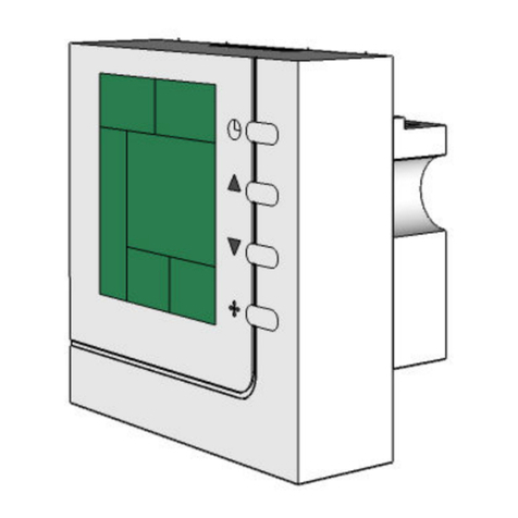
EC CONTROL: Cuadro de control y regulación automática para sistemas de ventilación con motores EC.
IMPORTANTE: Producto no apto para su uso en atmosferas explosivas o seguridad de incendios.
3. Información general
• Verifique siempre los productos recepcionados.
• Después de desembalar el equipo debe comprobarse que no tiene desperfectos. Nunca debe instalar productos
dañados
• No debe usar este equipo para propósitos distintos para los cuales fue diseñado, solo debe operar en las
condiciones citadas en este manual.
• En caso de defecto o malfuncionamiento, debe informarse al representante autorizado, describiendo el problema,
a fin de coordinar su devolución o posible reparación.
• Antes de poner en marcha el equipo, es necesario asegurarse que se ha leído las instrucciones de seguridad e
instalación de este documento
4. Transporte, almacenamiento y manipulación
• Sujetar siempre el equipo por los puntos previstos. No levantar por los cables de alimentación, cajas de bornes,
bocas de impulsión o aspiración.
• Antes de la instalación almacene los equipos en lugar seco, limpio y resguardado de las inclemencias del tiempo.
5. Seguridad
• No desmonte ni modifique el equipo. Esto puede ser perjudicial para el equipo o incluso ser causa de accidentes.
• No debe introducirse ningún objeto o dedos en las rejillas protectoras de las bocas, o conductos. Si fuera así,
desconecte inmediatamente la alimentación del equipo.
• Nunca utilice un cable de alimentación si este está dañado.
• No opere el equipo si está instalado de forma forzada sobre una superficie curvada o inestable.
• No efectuar operaciones de inspección o mantenimiento del equipo sin antes asegurarse de:
o Haberlo desconectado de su acometida eléctrica.
o Que todos sus elementos estén en reposo.
• No debe operarse el equipo sin que haya sido correctamente instalado y protegidas las bocas de aspiración e
impulsión, en caso necesario.
Las diferentes Series de Ventiladores y Extractores del fabricante, han sido diseñados y fabricados teniendo en cuenta la
particularidad de Eliminación de Riesgo, para cumplir las condiciones de Seguridad Integrada.
Cuando su configuración y proceso de fabricación lo permiten, el fabricante incorpora directamente los dispositivos de
Seguridad más adecuados. Si por sus condiciones de montaje o aplicación, ello no es posible en su origen, se dispone de
todos los accesorios adicionales de Seguridad, para que sean implementados en el momento de su Instalación antes de la
entrada en servicio.

ES
6. Conexiones eléctricas
• El equipo viene conectado de fábrica, el usuario debe conectar el interruptor del EC CONTROL con la manguera
de alimentación externa, también tiene que conectar las tomas de presión del equipo.
• Seleccione un cable de alimentación con una sección acorde con la intensidad del equipo.
• Debe conectarse la toma de tierra del equipo.
ºC Puede conectarse un sensor para medir la temperatura en ºC. (0 – 10V o 4-20mA)
HR% Puede conectarse un sensor para medir el porcentaje de humidad. (0 – 10V o 4-20mA)
CO
2
Puede conectarse un sensor para medir el nivel de CO
2.
(0 – 10V o 4-20mA)
NTC/PT100 Entrada NCT o PT100
0-10V CONTROL Control de señal de salida de 0–10V
USB Puerto de entrada USB
MODBUS Puerto de modbus
PWM Entrada de señal PWM, necesaria para el control de velocidad del ventilador
I/O Puertos de entradas y salidas digitales
ANALOG INPUT 1 Configurable des de “APP” para conexión de los sensores de ºC, HR, CO
2
o NTC/PT100
RELAY OUT Salida de conexión de relé
230V POWER SUPPLY Alimentación a 100-230VAC – 50/60Hz

ES
7. Configuración de I/O
Para la configuración de la función day/night aparecerá un valor de referencia distinto según la configuración establecida.
Si la entrada no está activa (NO) y el modo de trabajo se encuentra en modo CPC el valor de presión será el
configurado en PRESION REF 1. Pero si el modo de trabajo establecido es min/máx. el valor será el establecido
en el valor de referencia como valor mínimo.
Si la entrada está activa (NC) y el modo de trabajo se encuentra en modo CPC el valor de presión será el
configurado en PRESION REF 2. Pero si el modo de trabajo establecido es min/máx. el valor será el establecido
en el valor de referencia como valor máximo.
8. Configuración de software
Para la mejor configuración del CPC el equipo
viene con un software para PC.
El programa Sodeca CPC Utility permite al
usuario la elección del puerto al que quiere
conectarse, como el CPC permite configurar
las distintas aplicaciones i parámetros de los
equipos CPC:
caudal constante, con una
presión constante o con un valor Máximo y un
valor Mínimo. En el cuadro de texto debajo de
la pestaña “show last logs” hay un cuadro de
texto que permite ver los últimos errores que
se han producido en el equipo. Se puede
disponer de un histórico de errores
seleccionando la pestaña “show last logs”.
Con el historial de errores que se han
detectado en el equipo.
Si el equipo no se encuentra alimentado por ninguna fuente eléctrica y existe la opción de alimentar la placa electrónica a
través del PC. Para ello se debe activar el “jumper J22” i mediante el puerto USB se alimenta la placa electrónica.
9. Configuración de los menus de navegación
Los pulsadores A y C se utilizan para cambiar de menú de configuración. Para seleccionar el menú al que se quiere acceder
se usara el pulsador B.
Una vez dentro del menú de configuración, aparecerá un valor de forma intermitente. Para aumentar el valor usaremos el
pulsador C y para disminuir el valor usaremos el pulsador A. Una vez definido el nuevo valor, se usara el pulsador B para
fijarlo y poder cambiar de pantalla.
PANTALLA LCD
A B C D
SW3 SW4 SW1 SW2
A: Retroceder
B: Seleccionar
C: Avanzar
D: Rese
t

ES
9.1 STATUS
En este menú aparecerá el estado normal de funcionamiento del equipo y el valor de regulación (Pa, m
3
/h, %...)
dependiendo el modo de trabajo configurado y su unidad de medida. Una vez en el menú STATUS a través de los
pulsadores A y C se puede cambiar de menú de configuración. Para acceder al menú deseado se usara el pulsador B.
Este procedimiento también será utilizado dentro de cada menú de configuración. Si en el menú STATUS se acciona el
pulsador B se podrán ver los valores actuales del equipo que serán informativos y no modificables.
STATUS
CONFIGURACIÓN
IDIOMA
CONFIGURACIÓN
APP
CONFIGURACIÓN
PARAMETROS
CONFIGURACIÓN
ALARMAS
CONFIGURACIÓN
MODBUS
MODO CPC
101 Pa
Si hay alguna alarma aparece un símbolo parecido al de la imagen.
También aparece un mensaje de la alarma correspondiente alternado con
la imagen da la pantalla normal.
Línea superior: MODO de TRABAJO SELECCIONADO
Línea inferior: Muestra la lectura de PRESIÓN o CAUDAL y LA UNIDAD de
MEDIDA, en el caso de Min/Max se mostrará el SETPOINT que actúa en %.
CONSIGNA MOTOR
24%
Visualizar Salida de 0-10V.
0V = 0%
10V = 100%
RPM
1200
Visualizar RPM en función de entrada TACO
VERSIÓN FIRMWARE
V0.1
FECHA FABRICACIÓN
01/01/2017
Esta fecha será guardada del PC cuando se programe la placa
y será fija.

ES
9.2 CONFIGURACIÓN “IDIOMA”
En el menú de CONFIGURACION de “IDIOMA”
se podrá seleccionar el idioma en inglés o español.
Una vez seleccionado se debe guardar la configuración.
9.3 CONFIGURACION “APP”
En el menú de CONFIGURACIÓN de “APP”, se puede seleccionar el modo en el que se quiere trabajar. Modo CPC, Modo
CFC o Modo Mín./Max. Una vez seleccionado el modo de trabajo se podrán configurar las características que se encuentran
en el siguiente esquema.
CONFIGURACIÓN
APP
MODO TRABAJO
CPC
MODO TRABAJO
CFC
MODO TRABAJO
Mín/Max
UNIDADES
MEDIDA Pa
PRESION REF 1
100 Pa
PRESION REF 2
100 Pa
VALOR P
180
VALOR I
4,00
TIEMPO
RESPUESTA 2 s
VALOR I
4,00
VALOR P
180
CAUDAL REF.
500 m
3
/h
CAUDAL MAX.
1000 m
3
/h
VALOR FACTOR
K 300
UNIDAD DE
MEDIDA m
3
/h
UNIDADES
MEDIDA Pa
VALOR MIN.
25
%
VALOR MAX.
80
%
GUARDAR CONFIG?
SI
Selección
unidades de
medida:
Mode CPC: Pa,
kPa, mbar, inWC
o mmWc.
Selección
SETPOINT
RANGO: 0 a
2500
Selección
SETPOINT: esta
funciona si entrada
day/night esta
activada
RANGO: 0 a 2500
Selección banda
Proporcional
RANGO: 0 a 20
Selección
tiempo integral
RANGO: 0 a 10
Selección
unidades de
medida:
Mode CFC: m
3
/s,
m
3
/h, cfm, l/s
Selección
factor k:
RANGO:
1 a 1000
Selección
cabal máximo
RANGO:
1 a 30.000
Selección
SETPOINT
RANGO: 1
a 30.000
Selección
banda
Proporcional
RANG: 0 a 20
Selección
tiempo integral
RAN
GO
:
0
a
1
0
Selección unidad
de mesura:
Min/Max: Pa,
kPa, mbar, inWC
o mmW
c
NOTA: %
SALIDA 0–10V
motor
RANGO: 0 a 100
NOTA: %
SALIDA 0–10V
motor
RANGO: 0 a 100
Selección tiempo de
respuesta del regulador
RANGO: 0 a 20
Si o No
CONFIGURACIÓN
IDIOMA
IDIOMA
Español
GUARDAR CONFIG?
SI
ENGLISH I ESPAÑOL
Si o No
MODO TRABAJO
CONFIG ANI1
ESTADO ANI1
DESACTIVAR
MODO ANI1
SENSOR TEMP
PRIORIDAD PID
SENSOR PRESION
CONSIGNA ANI1
20 ºC
TIPO ANI1
ANI1 1-10V
VALOR MAX
ANI1 100 ºC
Selección
estado entrada
analógica
Activar o
Desactiva
r
Selección tipo
de sensor:
Sensor Temp,
Humedad, CO2
Sensor ANI1
o Sensor
presión
Unidades en función de ANI1:
- Temp: Def. 20ºC Rango 0-100ºC
- HUM: Def. 50% Rango 0-100%
- CO2: Def. 100PPM Rango 0-5000
ANI1 0-10V o
ANI1 0-20mA
Unidades en función de ANI1:
- Temp: Def. 20ºC Rango 0-100ºC
- HUM: Def. 50% Rango 0-100%
- CO2: Def. 100PPM Rango 0-5000

ES
9.4 CONFIGURACIÓN “PARAMETROS”
El menú de parámetros permite la configuración de distintas funciones como la configuración del pulsador SW2, la
configuración de las RPM e incluso hacer un restore.
CONFIGURACIÓN
PARAMETROS
FUNCION SW2
Reset Alarm
CONFIG. RPM
1400
RESTORE
SI?
GUARDAR
CONFIG?
Selección función 4 switch:
Reset alarms, Autozero (sensor de presión), GO
STATUS, ON/OFF ventilador
Selección de revoluciones:
Rango: 500 a 35000.
Este parámetro afecta a la alarma de control de
velocidad el motor
Selección RESTORE A CONFIGURACIÓN DE
FÁBRICA:
Si o No

ES
9.5 CONFIGURACIÓN “ALARMAS”
El menú de alarmas permite la configuración de las distintas alarmas que se encuentran en el sistema. Se puede
seleccionar el tipo de alarma del regulador, se puede activar o desactivar la alarma que indica si el equipo llega a la
consigna programada inicialmente, permite activar o desactivar la alarma que informa de la obtención de la lectura del
sensor de presión y activar la alarma de comunicaciones.
CONFIGURACIÓN
ALARMAS
ALARMA REGULADOR
Taco
Selección de alarma del regulador:
TACO, VSD o DESACTIVAR
ALARMA REF.
ACTIVAR
Selección de alarma que indica si se llega a la
consigna programada:
ACTIVAR o DESACTIVAR
ALARMA S. PRESIÓN
ACTIVAR
Selección de alarma que indica que no se obtiene
lectura del sensor.
ACTIVAR o DESACTIVAR
ALARMA MODBUS
ACTIVAR
Selección de alarma de comunicaciones:
ACTIVAR o DESACTIVAR
GUARDAR CONFIG?
Si SI o NO

ES
9.6 CONFIGURACIÓN “MODBUS”
Este menú permite configurar el modbus del equipo. El equipo usa una conexión ModBus RTU.
CONFIGURACIÓN
MODBUS
ID DISPORITIVO
12
Selección de la DIRECCIÓN del EQUIPO:
RANGO: 1 a 257
BAUD RATE
9600
Selección de VELOCIDAD:
9600, 19200 o 38400
DATA BITS
8 Rango: 7 o 8
BIT PARIDAD
NON
Selección de PARIDAD:
NON, EVEN o ODD
BITS STOP
0
Rango: 0, 1 o 2
READ TIMEOUT
20 ms
Rango 1 a 2000
GUARDAR CONFIG?
Si
SI o NO

ES
9.7 Tabla de registros
NOMBREREGISTRO NUM
REGISTRO VALORES DESCRIPCIÓN FUNCTION
MODOTRABAJOAPP
1 0 CPC (PRESI
Ó
N CONSTANTE) READ(04)/WRITE(06)
1 1 CFC (CAUDAL CONSTANTE) READ(04)/WRITE(06)
1 2 MIN/MAX READ(04)/WRITE(06)
UNIDADESDEMEDIDACPC 2 0……..X Pa, mbar, m3/h… READ(04)/WRITE(06)
UNIDADESDEMEDIDACFC 3 0……..X Pa, mbar, m3/h… READ(04)/WRITE(06)
PRESIÓN 4 0……..X lectura real sonda READ(04)
CAUDAL 5 0……..X lectura real caudal READ(04)
PRESIONREF1 6 0……..X SETPOINT PRESI
Ó
REF 1 READ(04)/WRITE(06)
PRESIONREF2 7 0……..X SETPOINT PRESI
Ó
REF 2 READ(04)/WRITE(06)
CAUDALMAX 8 1….30000 CAUDAL MAXIMO DEL VENTILADOR READ(04)/WRITE(06)
CAUDALREF 9 1….30000 SETPOINT CAUDAL READ(04)/WRITE(06)
VALORMIN 10 0-->100 % VALOR SALIDA CONSIGNA MOTOR MIN READ(04)/WRITE(06)
VALORMAX 11 0-->100 % VALOR SALIDA CONSIGNA MOTOR MIN READ(04)/WRITE(06)
VALORTACOMETRO 12 0……..X Valor en Hz de motor. READ(04)
VALORPCPC 13 0……..X VALOR GANANCIA PROPORCIONAL READ(04)(04)/WRITE(06)
VALORICPC 14 0……..X VALOR INTEGRACI
Ó
N READ(04)/WRITE(06)
VALORPCFC 15 0……..X VALOR GANANCIA PROPORCIONAL READ(04)/WRITE(06)
VALORICFC 16 0……..X VALOR INTEGRACI
Ó
N READ(04)/WRITE(06)
VALORK 17 0……..X FACTOR K DEL VENTILADOR READ(04)/WRITE(06)
VERSIONFIRMWARE 18 0……..X FIRMWARE INSTALDO EN EL CONTROLADOR READ(04)
FECHAFABRICACIÓN 19 0……..X FECHA DE FABRICACI
Ó
N READ(04)
ALARMAS
20 0 NO HAY ALARMAS READ(04)
20 1 ALARMA REGULADOR READ(04)
20 2 ALARMA REF READ(04)
20 3 ALARMA S.PRESSIO READ(04)
20 4 ALARMA MODBUS READ(04)
RESETALARMAS 0 --- WRITE(06)
21 1 RESET ALARMAS ACTIVAS WRITE(06)
FUNCIÓNSWITCH4
22 0 RESET ALARMAS ACTIVAS READ(04)/WRITE(06)
22 1 AUTOZERO READ(04)/WRITE(06)
22 2 GO STATUS READ(04)/WRITE(06)
VALORCONSIGNAMOTOR 23 0……..X % VALOR SALIDA CONTROL MOTOR 0--100% READ(04)
IDIOMA
24 0 ESPAÑOL READ(04)/WRITE(06)
24 1 ENGLISH READ(04)/WRITE(06)
2 - RESERVA - READ(04)/WRITE(06)
3 - RESERVA - READ(04)/WRITE(06)
4 - RESERVA - READ(04)/WRITE(06)
5 - RESERVA - READ(04)/WRITE(06)
6 - RESERVA - READ(04)/WRITE(06)
7 - RESERVA - READ(04)/WRITE(06)
8 - RESERVA - READ(04)/WRITE(06)
9 - RESERVA - READ(04)/WRITE(06)
RESTOREFABRICA 25 0 - - - - WRITE(06)
25 1 RESET VALORES DE FABRICA WRITE(06)
ALARMAREGULADOR
26 0 TACO READ(04)/WRITE(06)
26 1 VSD READ(04)/WRITE(06)
26 2 DESACTIVAR READ(04)/WRITE(06)
ALARMAREF 27 0 ACTIVAR READ(04)/WRITE(06)
27 1 DESACTIVAR READ(04)/WRITE(06)
ALARMAS.PRESIÓN 28 0 ACTIVAR READ(04)/WRITE(06)
28 1 DESACTIVAR READ(04)/WRITE(06)
ALARMAMODBUS 29 0 ACTIVAR READ(04)/WRITE(06)
29 1 DESACTIVAR READ(04)/WRITE(06)
MODBUSID 30 1 --> 257 ID DISPOSITIVO READ(04)/WRITE(06)
BAUDRATE
31 0 9600 READ(04)/WRITE(06)
31 1 19200 READ(04)/WRITE(06)
31 2 38400 READ(04)/WRITE(06)
DATABITS 32 0 7 BITS READ(04)/WRITE(06)
32 1 8 BITS READ(04)/WRITE(06)
BITPARIDAD
33 0 NON READ(04)/WRITE(06)
33 1 EVEN READ(04)/WRITE(06)
33 2 ODD READ(04)/WRITE(06)
BITSSTOP
34 0 0 READ(04)/WRITE(06)
34 1 1 READ(04)/WRITE(06)
34 2 2 READ(04)/WRITE(06)
READ(04)TIMEOUT 35 1 --> 2000 TIEMPO DE TIMEOUT EN ms READ(04)/WRITE(06)

ES
10. Selección de producto
Para seleccionar el producto adecuado, es necesario hacer un procedimiento similar al de la tabla que hay a continuación
Control de presión constante a la impulsión.
Control de presión constante a la aspiración.
Diagrama de conexión entre el dispositivo CPC con el
ventilador.
Conectar la toma positiva de la CPC hacia la toma de la
boca de impulsión del ventilador.
Diagrama de conexión entre el dispositivo CPC con el
ventilador.
Conectar la toma negativa de la CPC hacia la toma de
la boca de aspiración del ventilador.
En este tipo de instalaciones el Set
Point del CPC coincide con la pérdida
de carga total del sistema.
Para definir el Set Point de
Presión, debe observar en la
gráfica el punto de servicio, donde
entran en contacto la curva del
sistema con la del ventilador a
velocidad máxima. El valor de
presión en este punto es el valor
de presión a programar en el Set
Point del CPC.
En esta gráfica utilizada como
ejemplo el valor de presión a
programar es de 250 Pa.

ES
Control de presión constante de aspiración e impulsión.
Fig.1 Control de presión a la impulsión.
Diagrama de conexión entre el dispositivo CPC con el
ventilador.
Conectar la toma positiva de la CPC hacia la toma de la
boca de impulsión del ventilador.
Fig.2 Control de presión a la aspiración
Diagrama de conexión entre el dispositivo CPC con el
ventilador.
Conectar la toma negativa de la CPC hacia la toma de la
boca de aspiración del ventilador.
Fig.1 Fig.2
En este tipo de instalaciones el Set Point
del CPC NO coincide con la pérdida de
carga total del sistema.
Una vez encontrado el caudal del punto
de servicio, se tendrá que tener por
separado en este caudal la pérdida de
carga a la aspiración y a la impulsión.
Según dónde se conecte el CPC a la
instalación, impulsión (Fig.1) o
aspiración (Fig.2), el Set Point a
programar será la pérdida de carga a
la aspiración o impulsión en el caudal
del punto de servicio.
En esta gráfica utilizada como ejemplo
el valor de presión a programar es de
200 Pa si se tiene una instalación
como la Figura 2. Si se tiene una
instalación como la Figura 1 será de
100 Pa.

ES
11. Eliminación
La eliminación descuidada del equipo o realizada de forma negligente puede causar contaminación. El proceso de
supresión debe ser realizado cumpliendo con las normativas aplicadas en cada país.
12. Garantía
El uso incorrecto del equipo y de las instrucciones contenidas en este manual puede suponer la anulación de la garantía.

EN
1. Start
All fans produced by SODECA, hereinafter the manufacturer, and the full line of accessories, have been manufactured in
accordance with the strictest standards in relation to quality assurance, systems and production processes.
Their project, testing, manufacture and control structure has been configured in line with EU standards and regulations,
especially in reference to current safety standards.
The materials used in our fans, and the standardised components of which they are made meet the same standards and,
when so required, are backed up by the corresponding quality certificates.
The Original Manual was written in Spanish
The manufacturer reserves the right to make modifications without prior notice
All the documentation in this manual is the property of the manufacturer, and its total or partial reproduction is prohibited.
2. Product Definition
EC CONTROL: Automatic regulation and control panel for ventilation systems with EC motors.
IMPORTANT: This product is not suitable for use in explosive environments or for fire safety.
3. General Information
• Always check the products received.
• After unpacking the equipment, it must be checked to make sure that it is not damaged. Damaged products must
never be installed.
• This equipment must not be used for purposes other than those for which it was designed; it must only operate
under the conditions described in this manual.
• In the event of a defect or malfunction, this must be reported to the authorised representative, with a description of
the problem, in order to coordinate its return or possible repair.
• Before starting up the equipment, it is important to ensure that the safety and installation instructions in this
document have been read.
4. Transportation, storage and handling
• Always hold the equipment at the points provided for this (Fig. 2). Do not lift it by the electrical cables, connection
boxes, or the air inlet or outlet.
• Before installation, store the equipment in a clean, dry place, protected from inclement weather.
5. Safety
• Do not disassemble or modify the equipment. This could negatively affect the equipment or even cause accidents.
• Do not put your fingers or any objects into the protective grilles on ducts, inlets or outlets. If this were to occur,
immediately disconnect the equipment's power supply.
• Never use a damaged power cable.
• Do not operate the equipment if it has been forcibly installed on a curved or unstable surface.
• Do not perform equipment inspection or maintenance without first checking the following:
o That the equipment has been disconnected from the electrical supply.
o That all its components are at rest.
• The equipment must not be operated unless it has been properly installed and the inlet and outlet have been
protected, if necessary.
In designing and manufacturing the various Series of the manufacturer's Fans and Extractors, Hazard Elimination has been
taken into account, in order to meet the conditions for Integrated Safety.
When their configuration and manufacturing processes permit this, the manufacturer directly incorporates the most
appropriate Safety Devices. If the conditions for installation or use mean that these devices cannot be incorporated at source,
all additional safety accessories are available for implementation when the equipment is installed and before it is put into
service.

EN
6. Electrical connections
• The equipment is supplied ready-connected. Users should connect the CPC switch using the external supply cable
and also connect the equipment pressure fittings.
• Select a power cable with a cross-section that is suitable for the equipment current.
• The equipment ground wire must be connected.
ºC A sensor may be connected for measuring the temperature in ºC. (0 – 10V or 4-20mA)
HR% A sensor may be connected for measuring the humidity percentage. (0 – 10V or 4-20mA)
CO
2
A sensor may be connected for measuring the CO
2
level
(0 – 10V or 4-20mA)
NTC/PT100 NCT or PT100 input
0-10V CONTROL 0–10V output signal control
USB USB input port
MODBUS Modbus port
PWM PWM signal input, necessary for controlling the fan speed
I/O Digital input and output ports
ANALOG INPUT 1 Configurable from “APP” to connect ºC, RH, CO2 or NTC/PT100 sensors
RELAY OUT Relay connection output
230V POWER SUPPLY 100-230VAC – 50/60Hz power supply

EN
7. I/O configuration
To configure the day/night function a different reference value will appear, depending on the established configuration.
If the input is not operative (NO) and the work mode is the CPC mode, the pressure value will be that configured
in PRESSURE REF 1. If the work mode established is min/max., the value will be that established in the
reference value as the minimum value.
If the input is operative (NC) and the work mode is the CPC mode, the pressure value will be that configured in
PRESSURE REF 2. If the work mode established is min/max., the value will be that established in the reference
value as the maximum value.
8. Software configuration
To improve the CPC configuration, the
equipment is supplied with PC software.
The Sodeca CPC Utility programme allows
the user to choose the port to which they want
to be connected, as the CPC enables the
configuration of the different CPC equipment
applications and parameters:
constant flow
rate, with a constant pressure or with a
Maximum and a Minimum value. The text box
below the “show last logs” tab contains a text
box that displays the latest errors generated in
the equipment. An errors log can be obtained
by selecting the tab “show last logs”. With a
log of the errors detected in the equipment.
If the equipment is not supplied through an electrical power source and the option exists
of supplying the electronic board through the PC. To do this, activate the “jumper J22” and the electronic board is supplied
with power through the USB port.
9. Configuration of the browser menus
Buttons A and C are used to change the configuration menu. To select the menu to be accessed, click on button B.
Once inside the configuration menu, a flashing value will appear. To increase the value use button C and to reduce it, use
button A. Once the new value has been defined, use button B to
set it and change the screen.
LCD DISPLAY
A B C D
SW3 SW4 SW1 SW2
A: Back
B: Select
C: Forward
D:

EN
9.1 STATUS
In this menu the normal operating status of the equipment and the regulation value will be displayed (Pa, m
3
/h, %...)
depending on the work mode configured and its unit of measure. Once inside the STATUS menu, use buttons A and C to
change the configuration menu. To access the desired menu click on button B. This procedure will also be used in each
configuration menu. If button B is clicked in the STATUS menu, the current values of the equipment will be shown. These
are provided merely for information purposes and cannot be changed.
STATUS
CONFIGURATION
LANGUAGE
CONFIGURATION
APP
CONFIGURATION
PARAMETERS
CONFIGURATION
ALARMS
CONFIGURATION
MODBUS
CPC MODE
101 Pa
If an alarm is triggered, a symbol like the one in the image will appear. A
message from the respective alarm will also appear, alternating with the
normal screen image.
Top line: SELECTED WORK MODE
Bottom line: Shows the PRESSURE or FLOW RATE reading and the UNIT of
MEASURE. In the case of Min/Max the SETPOINT is shown, which operates
as a %.
MOTOR SETPOINT
24%
View 0-10V Output.
0V = 0%
10V = 100%
RPM
1200
View RPM depending on TACHO input
VERSIÓN FIRMWARE
V0.1
DATE OF
MANUFACTURE
01/01/2017
This date must be saved in the PC when the board is
programmed, and it will be fixed.

EN
9.2 “LANGUAGE” CONFIGURATION
In the “LANGUAGE” CONFIGURATION menu
the English or the Spanish language may be selected.
Once selected, the configuration must be saved.
9.3 “APP” CONFIGURATION
In the “APP” CONFIGURATION menu the work mode can be selected. CPC Mode, CFC Mode or Min./Max. Mode Once
the work mode has been selected, the characteristics shown in the following diagram can be configured.
CONFIGURATION
LANGUAGE
LANGUAGE
Spanish
SAVE CONFIG?
YES
ENGLISH AND SPANISH
Yes or No
CONFIGURATION
APP
SAVE CONFIG?
YES
Yes o No
MAX. VALUE
80
%
MIN. VALUE
25
%
UNITS OF
MEASURE Pa
WORK MODE
Mín/Max
WORK MODE
CFC
Proportional band
selection
RANGE: 0 to 20
WORK MODE
CPC
UNITS OF
MEASURE Pa
PRESSURE
REF 2 100 Pa
I VALUE
4,00
RESPONSE TIME
2 s
Integral time
selection
RANGE: 0 to 10
SETPOINT
selection
RANGE 0 to
2500
P VALUE
180
WORK MODE
CONFIG ANI1
Unit of measure
selection:
Min/Max Pa,
kPa, mbar, inWC
or mmW
c
Unit of measure
selection:
CFC Mode:
m3/s, m3/h,
cfm, l/s
Unit of measure
selection:
CPC Mode: Pa,
kPa, mbar, inWC
or mmWc
Analog input
status selection
Activate or
Deactivate
UNITS OF
MEASURE m
3
/h
ANI1 STATUS
DEACTIVATE
K VALUE
FACTOR 300
K factor
selection:
RANGE:
1 to 1000
REF. FLOW
RATE 500 m
3
/h
SETPOINT
selection:
RANGE: 1
to 30.000
P VALOR
180
I VALOR
4,00
PRESSURE
REF 1 100 Pa
NOTE %:
OUTPUT 0-10V
Motor
RANGE: 0 to 100
ANI1 Sensor
or Pressure
sensor
ANI1 MODE
TEMP SENSOR
PID PRIORITY
PRESSURE SENSOR
Maximum flow
rate selection.
RANGE:
1 to 30.000
MAX. FLOW
RATE 1000 m
3
/h
SETPOINT
selection:
This functions if
the day/night input
is operative
RANGE: 0 to 2500
Sensor type
selection:
Temp Sensor,
Humidity, CO2
NOTE %:
OUTPUT 0-10V
Motor
RANGE: 0 to 100
ANI1 units according to:
- Temp: Def. 20ºC Range 0-100ºC
- HUM: Def. 50% Range 0-100%
- CO2: Def. 100PPM Ran
g
e 0-5000
ANI1 SETPOINT
20 ºC
Proportional
band selection:
RANGE: 0 to 20
ANI1 TYPE
ANI1 1-10V
ANI1 0-10V or
ANI1 0-20mA
Integral time
selection:
RAN
G
E:
0
t
o
1
0
ANI1 units according to:
- Temp: Def. 20ºC Range 0-100ºC
- HUM: Def. 50% Range 0-100%
- CO2: Def. 100PPM Range 0-5000
MAX VALUE
ANI1 100 ºC
Regulator response
time selection
RANGE: 0 to 20

EN
9.4 “PARAMETERS” CONFIGURATION
The parameters menu permits the configuration of different functions such as the configuration of button SW2, the
configuration of the RPM and also allows a restore operation to be made.
CONFIGURATION
PARAMETERS
SW2 FUNCTION
Reset Alarm
CONFIG RPM
1400
RESTORE
YES ?
SAVE CONFIG ?
Function 4 switch selection:
Reset alarms, Autozero (pressure sensor), GO
STATUS
Revolutions selection:
Range: 500 to 35000
This parameter affects the motor speed
control alarm.
RESTORE TO FACTORY CONFIGURATION
selection:
Yes or No

EN
9.5 “ALARMS” CONFIGURATION
The alarms menu permits the configuration of the different alarms inside the system. It permits the selection of the
regulator alarm type, the activation or deactivation of the alarm indicating whether the equipment has reached the initially
programmed setpoint, the activation or deactivation of the alarm informing that the pressure sensor has obtained the
reading and the activation of the communications alarm.
CONFIGURATION
ALARMS
REGULATOR ALARM
Tacho
REF. ALARM
ACTIVATE
OVERPRESSURE
ALARM
ACTIVATE
MODBUS ALARM
ACTIVATE
SAVE CONFIG?
YES
Regulator alarm selection:
TACHO, VSD or DESACTIVATE
Selection of alarm indicating whether the
programmed set point was reached:
ACTIVATED or DESACTIVATE
Selection of the alarm indicating that the
sensor reading was not obtained:
TACHO, VSD or DESACTIVATE
Communications alarm section:
TACHO, VSD or DESACTIVATE
YES or NO
Table of contents
Languages:
Other SODECA Controllers manuals
