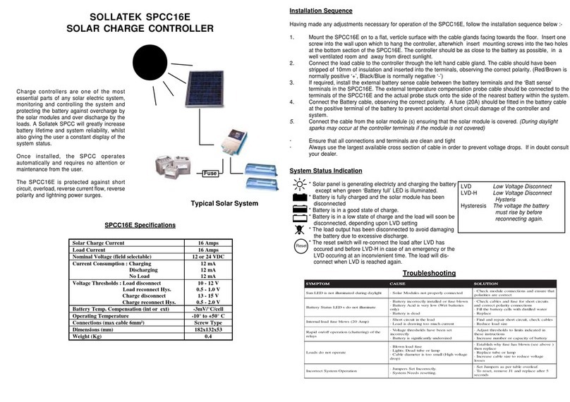
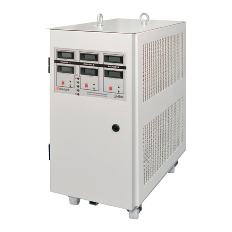
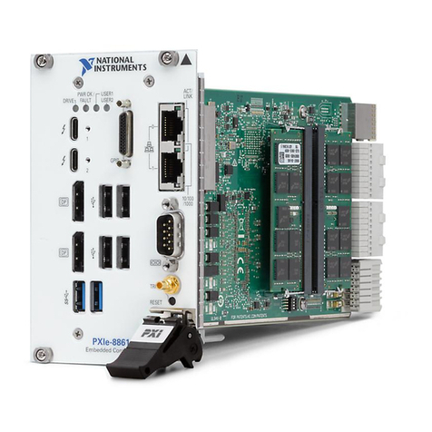
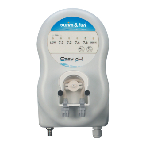
Sollatek FDEx2 User manual

Original
New CMYK
New Pantone 641C / 299C
the power to protect
81/15/0/0 Gradient
Process Cyan C - 299C is a better match!
299 C Gradient
92/58/8/0
641 C
CMYK
Pantone
TM
A3 CMYK
Important: This manual contains important safety instructions. Before using this product please read
all instructions carefully. Keep this manual handy for reference.
FDEx2
Electronic Refrigeration Controller with Always-On, Wi-Fi
and Bluetooth
USER INSTRUCTIONS

FDEx2 INSTRUCTION MANUAL FDEx2 INSTRUCTION MANUAL
A3+ CMYK
2+44 (1753) 214 500 sollateksupport@sollatek.com3
A3+ CMYK
Please read the following warnings to maintain the safe function and continued performance of your Sollatek
device.
INSTALLATION
The mounting of the unit must be in accordance with orientation as specied in this manual. The device must only be installed
and congured by trained and authorized staff.
TEMPERATURE
The Sollatek device must only be subjected to temperatures as specied in this manual.
VIBRATION AND IMPACT
The device MUST be installed in such a way as to be protected from impact in operation. Do not hit or drop the device.
NO SERVICEABLE PARTS
There are no serviceable parts inside the device. Do NOT open the housing.
VOLTAGES
The Sollatek device must only be connected to power supplies that comply with the acceptable voltage ranges as specied in
this manual.
VOLTAGE FLUCTUATIONS AND SURGES
The Sollatek device has surge protection as specied in this manual. Exposure to surge voltages outside these limits, or
excessively repeated surges within the limits may cause damage to the electrical circuits.
CURRENTS
Outputs should not be connected to short circuits or to loads that exceed the currents as specied in this manual. Care must be
taken to ensure that cables and terminations are safely terminated.
SEGREGATION OF POWER AND SIGNAL CABLING
Correct segregation of power and signal cabling must be followed. Do not run power and signal cables together in the same
conduit. Induction from power cables may corrupt data signals, leading to incorrect operation.
CONSEQUENTIAL FAILURES
The Sollatek device includes features to protect both itself and connected components. However, failure of connected
components may cause damage to the controller and/or connected components. Critical or vulnerable components should be
protected independently against failure.
FIT FOR PURPOSE
The Sollatek device must only be used for the purpose and functions described in this manual. As each application requires a
different conguration and setup, no liability is accepted by Sollatek UK Ltd for the correct operation of the nal equipment.
Failure to comply with the warnings may result in the device becoming damaged leading to
premature failure or unsafe operation. In extreme cases failure to comply may cause a risk
of electrocution or re.
SAFETY PRECAUTIONS
Precautions should be taken when installing or disconnecting the device. Isolate the power supply
before installation or servicing.
Trained and Authorised personnel only should install/service this equipment.
THE DANGERS OF ELECTRICITY
Harm can be caused to any person when they are exposed to ‘live parts’ that are either touched directly or indirectly by means
of some conducting object or material. Voltages over 50 volts AC or 120 volts DC are considered hazardous.
Most electrical accidents occur because of individuals:
1. Are working on or near equipment, which is thought to be dead, but which is, in fact, live.
2. Are working on or near equipment, which is known to be live, but where those involved are without adequate training or
appropriate equipment, or they have not taken adequate precautions.
3. Misuse of equipment or use of electrical equipment which they know to be faulty.
REDUCING THE RISK OF ELECTRIC SHOCK
To reduce the risk of electric shock:
1. Install the device in an area free of conductive contaminants. The ambient temperature must not exceed 60°C.
2. Isolate the power to the device before installation, repair, or removal.
3. Use tools with insulated handles.
FIRST AID
Before commencing any work:
1. Find out the location of a suitably stocked rst aid box.
2. Find out the arrangements that exist on-site for rst aid, and who is responsible for taking charge of these.
DISPOSAL
Sollatek devices are subject to the EU directive 2012/19/EU and may also be subject to other national legislation for
the safe disposal of e-waste.
1. The device cannot be disposed of as municipal waste, and such waste should be collected and disposed of
separately.
2. The device can be disposed of through an approved WEEE collection point, or alternatively can be returned to
Sollatek UK Ltd at the end of its working life.
3. The device may contain hazardous substances, which if disposed of incorrectly may cause harm to the
environment and/or human health.
4. Penalties may be applicable for incorrect disposal, as specied by local legislation.
Sollatek devices comply with EU directive 2011/65/EU (RoHS).

FDEx2 INSTRUCTION MANUAL FDEx2 INSTRUCTION MANUAL
A3+ CMYK
4+44 (1753) 214 500 sollateksupport@sollatek.com5
A3+ CMYK
CONTENTS
1. INTRODUCTION 5
1.1 DESCRIPTION 5
1.2 MODEL VARIANTS 5
1.3 LED INDICATORS 6
2. FUNCTION 7
2.1 TEMPERATURE CONTROL 7
2.2 ENERGY SAVING 7
2.3 DEFROST CONTROL 7
2.4 VOLTAGE AND COMPRESSOR PROTECTION 7
3. OPERATION 8
3.1 STANDARD REGULATING MODE 8
3.2 DEFROST MODE 10
3.3 ENERGY SAVING MODE 11
4. FEATURES 12
4.1 TEMPERATURE BLIND TIME 12
4.2 BAD VOLTAGE BLIND TIME 12
4.3 TIMESAVE™ FUNCTION 13
4.4 INTELLIGENT TIME DELAY 13
4.5 CELLULAR CONNECTIVITY 14
4.6 BLUETOOTH CONNECTIVITY 14
4.7 GEO-LOCATION 14
4.8 INTERNAL RECHARGEABLE BATTERY 14
4.9 DIGITAL DISPLAY MODULE 14
5. INSTALLATION 15
5.1 FDEx2 DIMENSIONS 15
5.2 MOUNTING INSTRUCTIONS 15
5.3 INSERTING AND REMOVING THE SIM CARD 15
5.4 WIRING CONNECTIONS 16
5.5 INITIAL STARTUP 17
6. TESTING PROCEDURE 18
6.1 THERMOSTATIC FUNCTION 18
6.2 DEFROST FUNCTION 18
6.3 VOLTAGE PROTECTION FUNCTION 19
7. ALARMS & ERRORS 20
7.1 FREQUENCY MONITORING & ERROR DETECTION 20
7.2 REGULATION PROBE ERROR DETECTION 20
7.3 DEFROST PROBE ERROR DETECTION 21
7.4 INTERNAL FAULT DETECTION 21
8. CONFIGURATION 22
8.1 DESKTOP CONFIGURATION 22
8.2 REMOTE CONFIGURATION 24
9. PROGRAMMING 25
10. PARAMETERS 27
10.1 HARDWARE CONFIGURATION 27
10.2 RELAY CONFIGURATION (RELAY #2/#3) 27
10.3 TEMPERATURE CONTROL 29
10.4 ENERGY SAVING (TEMPERATURE SET-BACK) 30
10.5 DELAYS AND TIMERS 31
10.6 DEFROST FUNCTION 32
10.7 VOLTAGE PROTECTION 35
10.8 DOOR SWITCH OPERATION 35
10.9 HEATER FUNCTION 36
10.10 PROBE FAULT DETECTION (PROBE #1/#2) 36
10.11 TRANSMISSION AND GEO-LOCATION 37
11. SPECIFICATION 38
12. ACCESSORIES 40
13. VERSION HISTORY 41
1. INTRODUCTION
1.1 DESCRIPTION
The FDEx2 is a connected electronic refrigeration controller / Energy Management Device (EMD) designed to provide precise
and efficient refrigeration control for up to 3 outputs using up to 3 inputs (temperature sensors and/or door switch).
The FDEx2 provides always-on connectivity via cellular networks. Controller telemetry and performance data are sent to the
portal, which can be accessed on all devices with an internet connection. Wi-Fi sniffing provides precise asset tracking within
indoor/urban environments. The Internal battery allows the FDEx2 to transmit location data even in the event there is no mains
power.
The FDEx2 has internal Bluetooth allowing remote access via the Smart Device App to authorized service personnel to access
controller data logs and control parameters. BLE also transmits Eddystone and iBeacon for proximity marketing (nearby
customer engagement).
The FDEx2 is built to last, meeting industry benchmarks and offering voltage protection to all connected outputs. A compact
all-in-one design allows installation even when space is tight.
DEVICE OVERVIEW
1Mains and Output Connectors
2Temperature/door Sensor Connector
3Temperature Sensor Connector
4Program/door Sensor Connector
5External Module
6 LED Status Indicators
7SIM Card Slot
1.2 MODEL VARIANTS
The “x” in the part number FDEx2 indicates the number of controllable outputs. There are two models available:
FDE22 = 2 relays, 16 Amp compressor + 5 Amp
FDE32 = 3 relays, 16 Amp compressor + 2x 5 Amp

FDEx2 INSTRUCTION MANUAL FDEx2 INSTRUCTION MANUAL
A3+ CMYK
6+44 (1753) 214 500 sollateksupport@sollatek.com7
A3+ CMYK
1.3 LED INDICATORS
On. Voltage Good. Cooling Demand.
Probe #1 Fault. Compressor Configurable.
Probe #2 Fault. Compressor Configurable.
Mains Frequency Out of Range.
Off. Voltage Bad. Cooling Demand.
Defrost Mode.
Wait Period. Cooling Demand.
Wait Period. No Cooling Demand.
Mains Voltage Compressor Meaning
Within Under/Over Voltage Blind Time.
Solid ON
Flash fast every 2 secs
Flash fast twice every 2 secs
Flashing 0.1 sec ON / 0.1 sec OFF
Flashing 0.5 sec ON / 0.5 sec OFF
Flashing 4 secs ON / 4 secs OFF
Flashing 1 sec ON / 1 sec OFF
Flashing 2 secs ON / 2 secs OFF
Momentarily OFF
LED Description
Battery Charging when Powered by Mains.
Solid ON
OFF Battery Fully Charged when Powered by Mains
Pre Defrost Mode.Flashing 4 sec ON / 1 sec OFF
Drip Down Mode.Flashing 4 sec ON / 1 sec OFF
Drip Down Recovery Mode.Flashing 4 sec ON / 2 sec OFF
KEY On/good Off/bad Not relevant
GSM Powered Down
OFF
OFF
Searching for Network
Flashing 64 msec ON
/ 800 msec OFF
ON
Idle - Connected with Network
Flashing 64 msec ON
/ 200 msec OFF
ON
Data Transer in Progress
Flashing 64 msec ON
/ 600 msec OFF
ON
FDEx2-2BBW FDEx2-4BBW
OFF
OFF
Flashing 200 msec ON
/ 1800 msec OFF
ON
Flashing 125 msec ON
/ 125 msec OFF
ON
Flashing 1800 msec ON
/ 200 msec OFF
ON
2. FUNCTION
2.1 TEMPERATURE CONTROL
The FDEx2 is a microprocessor-based temperature controller utilising up to two NTC (Negative Temperature Coefficient) probes.
The cooler temperature is determined by measuring the temperature of either the return airflow or evaporator temperature
depending on where the customer prefers to fit the probe. This probe should be connected to the probe #1 connector.
The FDEx2 is a closed-loop temperature controller, turning the compressor OFF once the Cut-out set point has been reached
and then turning the compressor ON when the Cut-in temperature is reached. Users can set both the cut-in and cut-out values.
2.2 ENERGY SAVING
Commercial refrigeration is energy-hungry; With rising energy costs and growing environmental concerns, the FDEx2 allows you
to reduce energy consumption. You can:
• Cycle the Evaporator Fan: set the fan to cycle during operation as opposed to ON all the time.
• Temperature Setback Mode: Reduce the cooling demand by increasing the set temperature values. This will reduce how
hard the compressor must work and therefore reduce energy.
The setback is designed to be initiated when the store is closed. To activate Setback there must be no door activity for a
configurable set period.
2.3 DEFROST CONTROL
One of the primary functions of the FDEx2 controller is defrost management. The defrost cycle can be initiated or terminated
by either time or temperature (active).
Every system is different but usually, for the most efficient and satisfactory refrigeration operation, you would set the controller
parameters to initiate the fewest amount of defrosts in a day, for the shortest amount of time needed to clear the evaporator of
ice.
Usually, parameters will be set to terminate due to temperature with a fail-safe time backup to prevent prolonged defrost because
of defective defrost components or failures.
The FDEx2 supports Natural or Forced Defrost:
• Natural Defrost turns off the compressor and allows the evaporator to warm up normally.
• Forced Defrost turns the compressor and evaporator fan off and then turns a reverse fan to warm up the evaporator quicker
than natural defrost.
Standard operation during Defrost:
Natural Defrost Forced Defrost
Compressor: OFF Compressor: OFF
Evaporator Fan: ON Evaporator Fan: OFF
Reverse Fan or Heater: ON
2.4 VOLTAGE AND COMPRESSOR PROTECTION
The FDEx2 has built-in voltage protection including High / low voltage, spikes/surges, and frequency monitoring to protect the
controller and connected outputs to reduce equipment damage and downtime. The FDEx2 continually senses the mains supply,
on sensing bad voltage (voltage is higher or lower than the present acceptable limits) the FDEx2 will disconnect the compressor
and other connected outputs. Once the voltage becomes good, the FDEx2 will ensure the voltage remains good for a set period
(TIMESAVE™) before reconnecting power to the compressor and other connected outputs.
A minimum OFF period is essential in allowing compressor gases to neutralise, ensuring that the mains have stabilised before
re-connection and avoiding a locked rotor condition, however, any prolonged off time can affect cooler efficiency and or the
contents of the cooler. The FDEx2 will automatically adjust the reconnection period meaning the cooler will never be off for
longer than required.

FDEx2 INSTRUCTION MANUAL FDEx2 INSTRUCTION MANUAL
A3+ CMYK
8+44 (1753) 214 500 sollateksupport@sollatek.com9
A3+ CMYK
3. OPERATION
3.1 STANDARD REGULATING MODE
Cut in
Average
Cut out
On
HVD
Pull
down
Temperature
probe reading
3 min s
Intelligent time delay
Time
Mains power
Defrost period
Intelligent time delay
Accumulated Compressor run time
has reached defrost interval (e.g. 12 hours).
Compressor
Defrost is activated
Disconnect compressor;
voltage is above HVD
Disconnect compressor;
voltage is below LVD
Defrost is terminated
LVD
O
SOLLATEK INTELLIGENT CONTROLS

FDEx2 INSTRUCTION MANUAL FDEx2 INSTRUCTION MANUAL
A3+ CMYK
10+44 (1753) 214 500 sollateksupport@sollatek.com11
A3+ CMYK
3.2 DEFROST MODE
3.2.1 STANDARD DEFROST
Depending on the requirement, defrost can be triggered by either using the temperature or/and by time, when both settings are
enabled, whichever event happens first will trigger or end the defrost cycle.
The FDEx2 has a minimum defrost duration and minimum duration between defrost cycles which must be satisfied before it will
act no matter the status of the other parameters. This is to ensure the defrost cycle is not stopped too early or defrost cycles are
not initiated too close together.
Cut in
Average
Cut out
On
Temperature
probe reading
Time
Defrost period
Compressor
Defrost is activated
Defrost is terminated
O
Defrost period
Defrost is activated
Defrost is terminated
On
>Minimum Duration between Defrost Cycles >Minimum Defrost Duration
3.2.2 ADVANCED DEFROST MODES
The FDEx2 has optional advanced pre- and post-defrost settings that provide extra protection to the controller and compressor
as well as maximising defrost efficiency.
On
Time
Pre Defrost
Mode
Compressor
Defrost is activated
by temperature or
time
O
On
O
Aux 1
(Evapourator
Fan)
Defrost Mode Drip Down
Mode
Post Drip Down
Recovery Mode
Aux 2
(Heater)
On
O
Defrost ended by
temperature or
time
Aux 1 & 2
congurable
Aux 1 & 2
OFF
Aux 1 & 2
OFF
Aux 1 & 2
congurable
Compressor OFF during
ALL defrost modes
Post Drip Down
Recovery ended
by temperature
or time
3.3 ENERGY SAVING MODE
The FDEx2 has an Energy Saving mode that provides reduced compressor operation when the outlet is closed and no
customer demand by setting the cut-in and cut-out temperatures higher than in normal mode. When the FDEx2 does not
sense a door opening for the pre-set duration, then the FDEx2 will enter Energy Saving Mode and run using the energy-saving
cut-in and cut-out temperature. When the door is opened or the maximum energy-saving timer has elapsed, the FDEx2 will
resume normal operation.
CUT IN
CUT OUT
Eco Mode
Temperature
Time
Engery Saving Max Duration
OPEN
CLOSE
Door Switch
Energy Saving Mode
Door Close Duration
to Start Energy Saving
Door Open Duration to Exit Engery Saving
Energy Saving is activated Energy Saving is terminated
CUT IN
CUT OUT
ON
OFF
Compressor
Normal Mode
Temperature

FDEx2 INSTRUCTION MANUAL FDEx2 INSTRUCTION MANUAL
A3+ CMYK
12+44 (1753) 214 500 sollateksupport@sollatek.com13
A3+ CMYK
4. FEATURES
4.1 TEMPERATURE BLIND TIME
The software will ignore the sensor temperature reading for the first few seconds (a pre-set value of 10 seconds) after the
compressor is switched on. This is to prevent short-term thermal effects such as those caused by the fan starting to operate
causing disconnection.
Cut in
Average
Cut out
On
O
Less than
Temperature
Blind Time
Temperature
Compressor
4.2 BAD VOLTAGE BLIND TIME
The software permits high and low mains voltages transitions for short periods of time preventing inadvertent compressor stop-
starts. Present values of 0.5 and 2 seconds (configurable) respectively are implemented.
However, if the mains voltage becomes too extreme (HVD + 10%) and (LVD - 20%), the FDEx2 will immediately disconnect the
compressor.
IDH
HVD
LVD
IDL
On
O
Intelligent time delay
Less than 0.5 secs
Less than 2 secs
Intelligent time delay
High limit
Low limit
Mains power
Compressor
IDH= Immediate Disconnect High
IDL= Immediate Disconnect Low
4.3 TIMESAVE™ FUNCTION
The FDEx2 has a built-in sensing period after a bad voltage event. When the voltage returns to good after a bad voltage period
the FDEx2 will only reconnect power to the compressor and other connected outputs once it has sensed the voltage remains
within set limits for at least 10 seconds.
4.4 INTELLIGENT TIME DELAY
The FDEx2 controller has a built-in intelligent time delay of up to 5 minutes (customer configurable). After a compressor
disconnection period, either from cycling OFF, defrost, or HVD/LVD the FDEx2 will automatically adjust the time delay on the
disconnection period before allowing the compressor to turn ON. For example, if the Time delay is set to 3 minutes, a 2-minute
disconnection will result in only a 1-minute additional delay, making the total delay 3 minutes. Any disconnection of 3 minutes or
over and the FDEx2 will immediately turn the compressor ON.
The time delay is essential in allowing compressor gases to neutralise, ensuring that the mains have stabilised before
re-connection and avoiding a locked rotor condition.
Operation of time delays during normal operation:
Compressor
ON
OFF
ON
OFF
Intelligent Time
Delay (1 min)
Disconnection Period
(2 mins)
Compressor
Disconnection Period
(7 mins)
Operation of time delays during a brownout (bad voltage):
Compressor
Voltage GOOD Voltage BAD Voltage GOOD
ON
OFF
ON
OFF
TIMESAVE™
Intelligent Time
Delay (1 min)
Disconnection Period
(2 mins)
Compressor
Voltage GOOD Voltage BAD Voltage GOOD
TIMESAVE™
Disconnection Period
(7 mins)
*Above illustrations use intelligent time delay set to 3 minutes

FDEx2 INSTRUCTION MANUAL FDEx2 INSTRUCTION MANUAL
A3+ CMYK
14+44 (1753) 214 500 sollateksupport@sollatek.com15
A3+ CMYK
4.5 CELLULAR CONNECTIVITY
The FDEx2 is equipped with cellular connectivity capabilities of 2G or Cat-M (depending on the model), enabling it to transmit
data over the secure global network for you to access on the online portal for cooler monitoring. The online portal can be
accessed on any device with an internet connection. The FDEx2 is provided with a global roaming SIM pre-installed. Via the
online portal, you can:
• Detailed Reports - View a vast list of controller operational data such as temperature, event history, and faults.
• Intelligent Data Analysis - Monitor technical and operational data in easy-to-read graphs and charts.
• Accurate Sales Performance - view and analyse cooler KPIs for enhanced sales forecasting and strategy.
• Over the Air Parameter Configuration - View and configure predefined FDEx2 controller parameters for cooler optimisation
• Remote Cooler Shut-down - In the event the cooler is stolen, disable the cooler so it cannot be used. Once the cooler is
recovered the cooler can then be enabled.
The transmission interval of cooler health data can be configured via the Sollatek Smart Device Application. Health data will not
be transmitted while being powered by the battery.
4.6 BLUETOOTH CONNECTIVITY
FDEx2 controllers are equipped with Bluetooth capability, enabling them to connect to the Sollatek Smart device Application.
The Sollatek App has extensive cooler management capabilities providing technicians with all the tools to view and upload
controller status and event data.
• Real-time Data Analysis - View real-time telemetry data, operational status, and performance data.
• Cooler Event Log - Access all historical data that has occurred between store visits to identify any issues or problems.
• Manage Settings and Parameters - View and configure predefined FDEx2 controller parameters for cooler optimisation. Set
BLE Beaconing protocols and event logging.
• Connect to the Cloud - Upload data to the cloud for access on the online portal for further analysis.
The FDEx2 controller also features iBeacon and Eddystone Beacon capabilities allowing proximity marketing to send engaging
and interactive content to consumers’ smartphones while they buy in real-time.
4.7 GEO-LOCATION
The FDEx2 provides Wi-Fi geo-location for precise asset tracking anywhere in the world. The FDEx2 collects and sends Wi-Fi
signal strength and WAP information from nearby devices (without connecting to the Wi-Fi network). The system then uses the
leading Wi-Fi location database to determine the location of the FDEx2 and cooler. The location can be seen on a dynamic map
on the portal.
• View current and historic cooler location.
• Real-time tracking of cooler location during movement (depending on transmission interval set).
The transmission interval of Wi-Fi data is fully configurable via the Sollatek Smart Device Application.
In addition, a GPS module (GGR) can be connected to the FDEx2 to provide multi-GNSS including GPS, GLONASS & Galileo
positioning for more rural remote locations where Wi-Fi location may struggle to provide an accurate location.
4.8 INTERNAL RECHARGEABLE BATTERY
The internal battery allows the FDEx2 to transmit cooler location to the online portal in the event of no mains power.
The battery will last approximately 4 months on a single charge depending on the transmission interval.
CAUTION! RISK OF EXPLOSION
It is not recommended for users to replace the battery so please contact Sollatek. The replacement
battery should be of the same type.
Dispose of the used batteries according to national standards and directives.
4.9 DIGITAL DISPLAY MODULE
The FDEx2 can be connected to the Sollatek FDM4 and FDM5 digital displays. These allow you to:
• View and configure controller status/mode.
• Configure pre-set parameters.
• View controller alarms and faults.
5. INSTALLATION
5.1 FDEX2 DIMENSIONS
95.2
112
102.5
℄
18.8
18.8
R1.8
2.5
89
30
1.5
5.2 MOUNTING INSTRUCTIONS
WARNING!
FDEx2 MUST be mounted with terminals in an isolated area, either in a plastic or earthed metal case.
For the best signal, avoid mounting the FDEx2 near/behind metal surfaces and mount it as close to the front of the
cooler, facing the front plastic grid.
Note: The FDEx2 can be mounted horizontally or vertically
1. Mark and drill pilot holes in the surface where the FDEx2 is to be mounted.
Ensuring the holes are free of burrs and sharp edges.
2. Place the FDEx2 in place and insert the provided screws into the holes.
3. Tighten the screws using a screwdriver to secure the FDEx2 into position.
5.3 INSERTING AND REMOVING THE SIM CARD
Note: FDEx2 is provided with a SIM pre-installed
Insert the SIM card
1. Remove the plastic bung.
2. Insert the SIM card with the chip facing towards the
front of the unit as shown, until it clicks into place.
3. Replace the bung in the hole, ensuring it is fully
pressed down.
Remove the SIM card
1. Remove the bung and press the SIM card in until it clicks, and then slowly release it
2. The SIM card will pop up. Pull the SIM card out.
3. Replace the bung in the hole, ensuring it is fully pressed down.

FDEx2 INSTRUCTION MANUAL FDEx2 INSTRUCTION MANUAL
A3+ CMYK
16+44 (1753) 214 500 sollateksupport@sollatek.com17
A3+ CMYK
5.4 WIRING CONNECTIONS
DANGER! ELECTRIC SHOCK HAZARD - LIVE TERMINAL
This is a non-isolated product. The sensor inputs and outputs are not electrically isolated from the power terminals
therefore the supply MUST be disconnected from the controller before installing/disconnecting, repairing, or
programming the controller, inputs, outputs, and external devices.
Ensure exposed connectors/wires of connected inputs, outputs and external devices do not touch the frame or
chassis of the cooler or other enclosures otherwise, damage to the controller, equipment, and the cooler will occur.
This equipment is to be installed or serviced by trained personnel only.
OR
NLin
5 A
+-
12345*
+ -
SPP02
OR
* FDE32 models ONLY
Display OR
GPS Module
5.4.1 MAINS AND OUTPUT WIRING
DANGER! - LIVE TERMINAL
Isolate the supply before installing/disconnecting or repairing the controller. Failure to do so can result in damage
to equipment and electrical shock.
Ensure the connected load does not exceed the maximum relay rating it is connected to and the total current rating
ON at once does not exceed 18 Amps (FDE22/FDE32).
0.25” vertical male spade terminals are used for mains and output connectors. Connections should be made with equivalent
female crimp connectors.
1. Connect the Mains Neutral wire to terminal 1 (marked N) on the FDEx2.
2. Connect the Mains Live-In wire to terminal 2 (marked Lin) on the FDEx2.
3. Connect the Compressor Live wire to terminal 3 (marked ) on the FDEx2.
4. Connect the required output (commonly evaporator fan) Live wire to terminal 4 (Relay #2, marked ) on the FDEx2, if
required.
5. Connect the required output (commonly Lights) Live wire to terminal 5 (Relay #3, marked AUX) of the FDEx2, if required
(FDE32 ONLY)
6. Connect all output Neutrals to Mains Neutral.
Note: Output connectors are based on the default relay configuration, if the output configuration is changed via the FDEx2
configuration interface, then the equipment should be connected accordingly.
5.4.2 INPUT SENSOR WIRING
DANGER! - LIVE TERMINAL
Isolate the supply before installing/disconnecting or repairing the controller. Failure to do so can result in damage
to equipment and electrical shock.
WARNING!
If the probes placed in an accessible area have less than 1.4 mm insulation, then the probes need to be sleeved
(greater than 0.4mm thickness) to attain supplementary insulation.
Separate as much as possible the input sensors and cables carrying inductive load and power. Do Not run power
and signal cables together in the same conduit.
0.11” vertical male spade terminals are used for the P1 and P2 connectors on the FDEx2. Temperature probes and door switch
use a 2-way female crimp terminal connector.
1. Connect the Regulating temperature probe (typically air) to terminal P1 on the FDEx2.
2. Connect a second temperature probe or a door switch to terminal P2 on the FDEx2 as required.
3. Connect a door switch to the Prog port on the FDEx2 if 2 temperature probes and a door switch are required.
Note: The door switch port must be configured by using the configuration interface.
5.4.3 EXTERNAL DEVICE CONNECTION
DANGER! - LIVE TERMINAL
Isolate the supply before connecting/repairing/disconnecting external devices. Failure to do so can result in damage
to equipment and electrical shock.
Do not power the controller with connecting cables unconnected to devices as if exposed connectors were to touch
the frame or chassis of the cooler, damage to the controller, equipment, and the cooler will occur.
WARNING!
Separate as much as possible the input sensors and cables carrying inductive
load and power. Do Not run power and signal cables together in the same
conduit.
1. Insert the 6-way (3x2) connector of the connection cable into the module port on the
FDEx2. Ensure the connector is fully pushed down / securely in the socket.
2. Plug the other end of the connector cable into the device.
5.5 INITIAL STARTUP
5.5.1 CONTROLLER
Once power is supplied to the FDEx2, the FDEx2 will immediately start operating as per the set parameters. The set time delay
will be respected before turning the compressor and other relays ON.
5.5.2 BATTERY MODE TRANSMISSION
To comply with shipping regulations, transmissions on battery mode are disabled, this means the FDEx2 will NOT transmit data
to the portal while being powered by battery until it is enabled.
To enable battery mode transmission, the FDEx2 MUST be powered from mains for a minimum of 5 continuous minutes. After
this period, the FDEx2 will automatically enable this feature.

FDEx2 INSTRUCTION MANUAL FDEx2 INSTRUCTION MANUAL
A3+ CMYK
18+44 (1753) 214 500 sollateksupport@sollatek.com19
A3+ CMYK
6. TESTING PROCEDURE
6.1 THERMOSTATIC FUNCTION
1 2 3
1. Connect the FDEx2 to a source of variable AC voltage such as a Variac. Adjust the output of the Variac to a good starting
voltage (within the acceptable limits). The power LED will be flashing at a rate of 2 seconds ON / 2 seconds OFF if the
temperature detected by the regulation temperature probe (Probe#1) is below the cut-in temperature. If the temperature is
above the cut-in value, then the power LED will flash at a rate of 1 second ON / 1 second OFF
2. When the Intelligent Time Delay is over, the FDEx2 will connect the mains supply to the compressor (assuming the
temperature sensed by Probe#1 is above the cut-in temperature). The power LED will be ON.
3. Once the cabinet has reached the desired temperature (the temperature sensed by Probe#1 drops below the cut-out
temperature), the FDEx2 will disconnect the compressor and the power LED will be flashing at a rate of 2 seconds ON / 2
seconds OFF (which indicates the incoming voltage is good and compressor is satisfied).
6.2 DEFROST FUNCTION
Note: This test may take a long time to wait for either the defrost start time to be over or for the evaporator temperature to drop
below the defrost start temperature.
1 2 3
1. Connect the FDEx2 to a source of variable AC voltage such as a Variac. Adjust the output of the Variac to a good starting
voltage (within the acceptable limits). The power LED will flash at a rate of 1 second ON / 1 second OFF for the duration of
the protection time delay (assuming the temperature is above the cut-in value)
2. When the Intelligent Time Delay is over, the FDEx2 will turn on the compressor and the power LED will be ON.
3. The unit will go into defrost as soon as one of the defrost start criteria is met. This could be either defrost start time is over
or the evaporator temperature drops below defrost start temperature value, whichever happens first, or is activated. The
power LED will flash 4 seconds ON / 4 seconds OFF, and the compressor and other outputs will act according to the set
operation, turning ON if set to ON.
4. The unit will stay in defrost until one of the defrost end criteria is met. This could be either defrost end duration is over or the
evaporator temperature has risen above defrost end temperature value, whichever happens first, or is activated.
Test Operation - Immediate Defrost at Power UP Enabled
1. Connect the FDEx2 to a variable power source such as a variac and ensure the output of the Variac is at a good starting
voltage.
2. When powered up, if the defrost enable temperature is met, the FDEx2 will enter defrost. The power LED will flash 4 seconds
ON / 4 seconds OFF, and the compressor and other outputs will act according to the set operation, turning ON if set to ON.
3. The unit will stay in defrost until one of the defrost end criteria is met. This could be either defrost end duration is over or the
evaporator temperature has risen above defrost end temperature value, whichever happens first, or is activated.
Note: Ensure to disable this feature and reprogram the FDEx2 before sending the cooler/controller to market.
6.3 VOLTAGE PROTECTION FUNCTION
12
1. Connect the FDEx2 to a variable power source such as a variac and ensure the output of the Variac is at a good starting
voltage (within the acceptable limits). The power LED will be flashing at a rate of 1 second ON / 1 second OFF for the
duration of the protection time delay (assuming the temperature is above the cut-in value)
2. When the Intelligent Time Delay is over, the FDEx2 will turn on the compressor and the power LED will now be ON.
34
3. Slowly decrease the voltage until the power LED momentarily switches OFF. The power LED will stay OFF for the duration
of the Under Voltage Blind Time (2 seconds),
4. Then the FDEx2 will disconnect the outputs and the power LED starts flashing fast at a rate of 0.5 seconds ON / 0.5 seconds
OFF. This represents the Low Voltage Disconnect voltage.
56
5. Increase the voltage slowly until the power LED starts flashing at a slower rate (1 second ON/1 second OFF). This represents
the Low Voltage Reconnect voltage.
6. Wait for the Protection Time Delay, then the power LED will be ON.
7. Repeat steps 3 to 6 but increase the voltage to test the overvoltage.
• The High Voltage Blind Time is 0.5 seconds.
Note: Low/high Blind Times are Sollatek recommended timings. Blind times are configuarble in the desktop configuration
interface so actual timings may differ from the times stated depending on your settings.

FDEx2 INSTRUCTION MANUAL FDEx2 INSTRUCTION MANUAL
A3+ CMYK
20+44 (1753) 214 500 sollateksupport@sollatek.com21
A3+ CMYK
7. ALARMS & ERRORS
7.1 FREQUENCY MONITORING AND ERROR DETECTION
The FDEx2 dynamically measures the frequency of the mains supply and reacts accordingly. If the mains supply frequency is too
low or too high, the FDEx2 will then disconnect the compressor and indicate an error signal through the LEDs. The FDEx2 can
auto-recover once the frequency is within acceptable limits.
On
O
Mains power
Normal
frequency
35-75Hz
Intelligent time delay
High
frequency
>75Hz
Normal
frequency
35-75Hz
Low
frequency
<35Hz
Normal
frequency
35-75Hz
Compressor
Note: The above illustration assumes that the Mains voltage RMS value is good and there is cooling demand, hence the
compressor comes on after the intelligent time delay is over.
7.2 REGULATION PROBE (PROBE#1) ERROR DETECTION
The FDEx2 will report an error code through the LEDs indicating a sensor fault if it happens. Depending on customer preferences
the FDEx2 will either:
Scenario One: Detect the fault and disconnect the compressor until the problem is resolved and then the system resumes normal
operation.
Cut in
Average
Cut out
faulty
functioning
On
O
Temperature
reading
Probe
Compressor
Probe fault has
been detected.
Compressor
switches o
until the fault
is recovered.
Scenario Two: Detect the fault and cycle the compressor on and off for a pre-set time regardless of the cooler temperature. Once
the problem is resolved the system will resume normal operation.
Cut in
Average
Cut out
faulty
functioning
On
O
Temperature
reading
Probe
Compressor Probe fault has been detected.
Compressor cycles on and o
On
period
O
period
7.3 DEFROST PROBE (PROBE#2) ERROR DETECTION - EMERGENCY DEFROST MODE
If the defrost probe is faulty, the FDEx2 will enter emergency defrost mode (if enabled). In emergency defrost mode, the FDEx2
will ignore set defrost parameters and enter a state of continuous defrost cycling based on set parameters.
For example: The emergency defrost start time is set to 1 hour and the emergency defrost end time is set to 20 minutes.
After an hour after a defrost probe fault has been detected, the FDEx2 will enter defrost for 20 minutes before resuming normal
operation for 1 hour and so on until the probe fault has been fixed.
Cut in
Average
Cut out
faulty
functioning
On
O
Temperature
reading
Probe
Compressor
Probe fault has been detected.
Emergency Defrost Start Time -
Normal operation
Defrost
Period
Emergency Defrost Start Time -
Normal operation
7.4 INTERNAL FAULT DETECTION
If an internal fault within the FDEx2 is detected, it is reported through the LED indicator. If the fault does not automatically clear
and resumes normal operation, then please contact Sollatek for help and advice.

FDEx2 INSTRUCTION MANUAL FDEx2 INSTRUCTION MANUAL
A3+ CMYK
22+44 (1753) 214 500 sollateksupport@sollatek.com23
A3+ CMYK
8. CONFIGURATION
8.1 DESKTOP CONFIGURATION
The desktop configuration Interface is designed to set all refrigeration control parameters of the FDEx2, (see section 9.
Parameters for a full list of parameters).
8.1.1 INSTALLATION AND LOGIN
1. Run the .exe file provided by Sollatek.
2. Follow any security notifications to allow your PC to install the software.
3. The installer wizard window will appear on the screen. Follow the on-screen instructions in the wizard and enter the company
name and password, as provided by Sollatek.
4. The files and data will be automatically extracted without any user intervention. Progress will be indicated on the status bar
within the wizard.
5. Once the desktop configuration Interface has been installed on your computer the wizard will display a
success message and the program shortcut will be saved on your desktop.
6. Click Finish to close the wizard window.
7. The desktop configuration Interface can either be opened by searching in the start menu or clicking on the
desktop shortcut.
8.1.2 HOME WINDOW
When the desktop configuration interface is opened, the configuration interface window appears. The menu bar includes File,
Tools, and Help which have all the options for you to be able to configure / program the FDEx2.
12
3
Menu Item Description
1. File New - Open a blank configuration where values are set to default.
Open - Open a configuration file saved on your PC.
2. Tools Program - Program an SPP02 with a saved configuration file without
loading it into the configuration software.
3. Help About Programmer - Software details including software version.
8.1.3 PARAMETER CONFIGURATION WINDOW
The software is intuitive, so certain options can only be adjusted if a corresponding option is selected for example: Relay #3
configuration will only be accessible if the number of outputs in the hardware configuration is set to 3.
1
2
3
4
5
6
Button Description
1. Program Program current configuration & firmware to the SPP02.
2. Generate F/W*Save the configuration and firmware as program files on your computer. Several files
will be saved in the file location of your choice.
.s19 & option.s19 files will be used to program the FDEx2.
.cfg file is the parameters set in the desktop configuration interface.
.stp file can also be used to program the FDEx2.
3. Save Save the current configuration as a file on your computer. If saving for the first time
you must select the file name and location. Thereafter the file will overwrite the
existing file.
4. Save As Save a copy of the current configuration with a different name or different file
location on your computer.
5. Device Info Collect and view device information from a connected controller.
6. Close Close the parameter configuration widow - if changes have been made you will be
prompted if you want to save the changes.
* When you Generate F/W or Save As you will be asked if you want a specification sheet saving. This is a spreadsheet of all the
parameters and set values.
8.1.4 DEVICE SELECTION
The desktop interface can be used to program multiple Sollatek
Controllers. Before proceeding to make any changes to parameters,
ensure FDE is selected from the product family menu within the
hardware configuration section.
Note: Select the correct version number for the FDE you have, if
you are unsure, please contact Sollatek.
1
2
3
4
5
6

FDEx2 INSTRUCTION MANUAL FDEx2 INSTRUCTION MANUAL
A3+ CMYK
24+44 (1753) 214 500 sollateksupport@sollatek.com25
A3+ CMYK
8.1.5 REVIEW DEVICE FIRMWARE DETAILS
DANGER! ELECTRIC SHOCK HAZARD - LIVE TERMINAL
This is a non-isolated product. The sensor inputs and outputs are not electrically isolated from the power terminals
therefore ALL terminals are energized when the device is powered ON.
The FDEx2 desktop configuration interface allows users to collect key firmware details from a device by connecting it to a
computer.
1. Connect the FDEx2 interface cable to the 6-way module port on the top of the FDEx2 and the USB port on your computer.
WARNING! Only a Sollatek isolated interface cable is to be used, unapproved or unisolated cables will cause damage to
the FDEx2 and the computer.
2. Connect the controller to the mains supply (Live & Neutral), then turn the power ON.
DANGER! All terminals are energized - Ensure NOT to touch any of the input or output terminals.
3. Open the FDEx2 Configuration Interface.
4. Click the Device Info button on the right-hand side of the window.
5. Details from the FDEx2 will be read and a pop-up window will appear when all details have been collected.
Note: This may take a few minutes.
6. Click Ok to close the window.
Note: Firmware details and parameters can also be viewed from any FDEx2 via the android FreoUp application. Please refer to
the FreoUp manual for details.
8.2 REMOTE CONFIGURATION
Some parameters are configurable via the smart device application or via the buttons of a display (if connected), please refer to
the application/display instructions or contact Sollatek for more details.
Parameters configurable via the display:
• Set-point Normal (Compressor Cut-out)
• Differential Normal (Compressor Cut-in)
• Set-point Eco (Compressor Cut-out)
• Differential Eco (Compressor Cut-in)
• Door closure duration to trigger energy saving
• Display Off-set (difference between the display temperature and the actual temperature)
• Defrost start timer
• Defrost end timer
9. PROGRAMMING
FDEx2 firmware and configuration can be updated via the Sollatek Product
Programmer device (SPP02).
The SPP02 can be programmed directly from the controller configuration
software or the SPP visual programmer (refer to SPP Visual Programmer User
Instructions for details on this method) and then uploaded to the FDEx2.
PROGRAMMING THE SPP02
There are two ways of programming the SPP02 from the Controller desktop configuration interface.
• From the main menu - for quick programming with an existing configuration file.
• From the parameter configuration window - for programming when you have made changes / checked the configuration.
Downloading Parameters from the Home window.
1. Open the desktop configuration interface on your PC.
2. Plug the SPP02 into the USB port on your PC.
3. Click Tools > Program. Select a recently saved configuration or alternatively click Browse to search for the required
configuration file.
4. If the file is selected from the recent configuration window, then click proceed to start uploading, alternatively select a file
from the file window then programming will automatically start when you open the file.
5. During the programming of the SPP02, the green LED labelled on the SPP02 will light up and remain on as the data is
being downloaded.
6. On successful downloading, the green LED will start flashing and then turn OFF. A success message will also appear on the
screen. Click OK to close the message box. The SPP02 can now be removed from the computer.

FDEx2 INSTRUCTION MANUAL FDEx2 INSTRUCTION MANUAL
A3+ CMYK
26+44 (1753) 214 500 sollateksupport@sollatek.com27
A3+ CMYK
Downloading Parameters from the Parameter Configuration Window.
1. Open and edit/create a configuration to match your requirement.
2. Plug the SPP02 into the USB port in your computer, if plugging in for the first time please wait for all the drivers to be installed
before proceeding, this may take several minutes.
3. Click the Program button in the top right corner of the parameter configuration window.
4. During the programming of the SPP02, the LED on the SPP02 will light up and remain on as the data is being downloaded.
5. On successful downloading, the LED will start flashing and then turn OFF. A success message will also appear on the
screen.
6. Click OK to close the message box. The SPP02 can now be removed from the computer.
PROGRAMMING THE FDEX2
DANGER! ELECTRIC SHOCK HAZARD - LIVE TERMINAL
This is a non-isolated product. The sensor inputs and outputs are not electrically isolated from the power terminals
therefore the supply MUST be disconnected from the controller before programming the device. This Equipment
is to be serviced by trained personnel only.
1. Connect the mini-USB connector of the SPP02 to the mini-USB port on the extension cable.
2. Remove the bung from the micro-USB port on the FDEx2. Connect the micro-USB connector of the extension cable to the
Micro-USB port on the FDEx2.
3. Press the button on the side of the SPP02 programmer. The LED will light up and will remain on as the FDEx2 is being
programmed. The LED on the FDEx2 will also light up.
4. On Completion the LED will start flashing and turn OFF. The FDEx2 LED will also turn OFF.
5. Unplug the SPP02 and extension cable from the unit. Replace the bung to recover the micro-USB port. Reconnect mains to
the FDEx2. The FDEx2 is now ready for use.
Note: If you have any problems during programming or want to use the SPP Visual software to upload to the SPP02, then please
refer to the SPP02 Visual Programmer User Instructions for more details and troubleshooting.
10. PARAMETERS
10.1 HARDWARE CONFIGURATION
DESCRIPTION UNIT RANGE
Number of Outputs Number 1, 2 or 3
Number of Temperature Probes Number 1 or 2
Enable Door Switch Yes or No
Door Switch Port Selection Probe#2 Input or Prog Port
Number of Outputs
Select the number of connected outputs.
1 = Compressor
2 = Compressor + Aux 1
3 = Compressor + Aux 1 + Aux 2
Number of Temperature Probes
Select the number of connected temperature probes.
1 = Connect regulating probe to P1.
2 = Connect regulating probe to P1 and another probe to P2.
Enable Door Switch
Select whether a door switch is connected.
No = Door switch is disabled.
Yes = Door switch is enabled. You will now be able to set compressor actions based on a door event.
Door Switch Port Selection
Select the port the door switch is connected to on the FDE.
Probe#2 Input = Door switch is connected to P2. Only 1 temperature probe will be available for selection.
Prog Port = Door switch is connected to the micro-USB program port. 2 temperature probes will be available for
selection.
10.2 RELAY CONFIGURATION (RELAY #2/#3)
DESCRIPTION UNIT RANGE
Type of Load Compressor, Evap Fan, Cond Fan, Light, Heater,
Other
Operation When Compressor is On On, Off, Cycling, Heater
Cycling On Time (mins) Minutes 1 to 255
Cycling Off Time (mins) Minutes 1 to 255
Operation When Compressor is Off On, Off, Cycling, Heater
Cycling On Time (mins) Minutes 1 to 255
Cycling Off Time (mins) Minutes 1 to 255
Operation During Defrost On, Off, Cycling, Heater
Cycling On Time (mins) Minutes 1 to 255
Cycling Off Time (mins) Minutes 1 to 255
Operation When Probe#1 if Faulty On, Off, Cycling, Heater, On/Cycling, Same as
Comp
Cycling On Time (mins) Minutes 1 to 255
Cycling Off Time (mins) Minutes 1 to 255
Operation When Probe#2 if Faulty On, Off, Cycling, Heater, On/Cycling, Same as
Comp
Cycling On Time (mins) Minutes 1 to 255

FDEx2 INSTRUCTION MANUAL FDEx2 INSTRUCTION MANUAL
A3+ CMYK
28+44 (1753) 214 500 sollateksupport@sollatek.com29
A3+ CMYK
Cycling Off Time (mins) Minutes 1 to 255
Operation When Door is Open Normal or Off
Door Open Response Time (secs) Seconds N/A, 1 to 255
Door Close Response Time (secs) Seconds N/A, 1 to 255
Operation When in Post Drip Down Recovery On or Off
Type of Load
Select the type of load connected to the relay.
Operation When Compressor is ON
Select the operation of the relay when the compressor is ON.
On = Relay will turn ON (if OFF) and remain ON when the compressor is ON.
Off = Relay will turn OFF (if ON) and remain OFF when the compressor is ON.
Cycling = Relay will cycle ON / OFF for the dened periods while the compressor is ON.
Heater = Relay will turn ON (if OFF) when the temperature is less than the heater cut-in value and turn OFF (if ON) when the
temperature is more than the heater cut-out value during compressor ON.
Cycling ON Time
The duration the relay will turn ON for while the compressor is ON. After this, the relay will turn OFF.
Cycling OFF Time
The duration the relay will turn OFF for while the compressor is ON. After this, the relay will turn ON.
Operation When Compressor is Off
Select the operation of the relay when the compressor is OFF.
On = Relay will turn ON (if OFF) and remain ON when the compressor is OFF.
Off = Relay will turn OFF (if ON) and remain OFF when the compressor is OFF.
Cycling = Relay will cycle ON / OFF for the dened periods while the compressor is OFF.
Heater = Relay will turn ON (if OFF) when the temperature is less than the heater cut-in value and turn OFF (if ON) when the
temperature is more than the heater cut-out value during Compressor OFF.
Cycling ON Time
The duration the relay will turn ON for while the compressor is OFF. After this, the relay will turn OFF.
Cycling OFF Time
The duration the relay will turn OFF for while the compressor is OFF. After this, the relay will turn ON.
Operation During Defrost
Select the operation of the relay during defrost mode.
ON = Relay will turn ON (if OFF) and remain ON during defrost mode.
OFF = Relay will turn OFF (if ON) and remain OFF during defrost mode.
Cycling = Relay will cycle ON / OFF for the dened periods during defrost mode.
Heater = Relay will turn ON (if OFF) when the temperature is less than the heater cut-in value and turn OFF (if ON) when the
temperature is more than the heater cut-out value during defrost.
Cycling ON Time
The duration the relay will turn ON during defrost mode. After this, the relay will turn OFF.
Cycling OFF Time
The duration the relay will turn OFF during defrost mode. After this, the relay will turn ON.
Operation When Probe#1 Faulty
Select the operation of Relay #2 when probe #1 is faulty.
ON = Relay will turn ON (if OFF) and remain ON until probe #1 fault has been xed.
OFF = Relay will turn OFF (if ON) and remain OFF until probe #1 fault has been xed.
Cycling = Relay will cycle ON / OFF for the dened periods until probe #1 fault has been xed.
Heater = Relay will turn ON (if OFF) when the temperature is less than the heater cut-in value and turn OFF (if ON) when the
temperature is more than the heater cut-out value until probe #1 fault has been xed.
On/Cycling = Relay will be ON when the compressor is ON. When the compressor is OFF, the relay will cycle ON / OFF for the
dened periods until probe #1 fault has been xed.
Same as Comp = Relay will operate the same as the compressor until probe #1 fault has been xed.
Cycling ON Time
The duration the relay will turn ON for while probe #1 is faulty. After this, the relay will turn OFF.
Cycling OFF Time
The duration the relay will turn OFF for while probe #1 is faulty. After this, the relay will turn ON.
Operation When Probe#2 Faulty
Select the operation of the relay when probe #2 is faulty.
ON = Relay will turn ON (if OFF) and remain ON until probe #2 fault has been xed.
OFF = Relay will turn OFF (if ON) and remain OFF until probe #2 fault has been xed.
Cycling = Relay will cycle ON / OFF for the dened periods until probe #2 fault has been xed.
Heater = Relay will turn ON (if OFF) when the temperature is less than the heater cut-in value and turn OFF (if ON) when the
temperature is more than the heater cut-out value until probe #2 fault has been xed.
On/Cycling = Relay will be ON when the compressor is ON. When the compressor is OFF, the relay will cycle ON / OFF for the
dened periods until probe #2 fault has been xed.
Same as Comp = Relay will operate the same as the compressor until probe #2 fault has been xed.
Cycling ON Time
The duration the relay will turn ON for while probe #2 is faulty. After this, the relay will turn OFF.
Cycling OFF Time
The duration the relay will turn OFF for while probe #2 is faulty. After this, the relay will turn ON.
Operation When Door is Open
Select the operation of the relay when a door event occurs.
Normal = Relay will ignore the door event and operate as dened with the compressor.
Off = Relay will turn OFF (if ON) and remain OFF until the door has been closed. It will then resume normal operation
depending on the FDEx2 mode.
Door Open Response Time
The minimum duration for the door to remain open before the relay will turn OFF.
Door Close Response Time
The duration for the door to remain closed before the relay will resume normal operation.
Operation When in Post Drip Down Recovery
Select the operation of the relay when the FDEx2 is in Post Drip Down Recovery mode.
ON = Relay will turn ON (if OFF) and remain ON during Post Drip Down Recovery mode.
OFF = Relay will turn OFF (if ON) and remain OFF during Post Drip Down Recovery mode.
10.3 TEMPERATURE CONTROL
DESCRIPTION UNIT RANGE
Regulation Temperature Probe Probe#1 or Probe#2
Temperature Blind Time (secs) Seconds 0 to 125
Temperature Unit °C or °F
Temperature Display Off-set Value °C / °F -10 to +10°C / -18 to +18°F
Temperature Resolution Number 0.1, 0.5, 1.0
Normal Settings
Cut-In Temp °C / °F N/A, -40 to +70°C / -40 to 158°F
Cut-out Temp °C / °F N/A, -40 to +70°C / -40 to 158°F
Set-back Settings
Cut-In Temp °C / °F N/A, -40 to +70°C / -40 to 158°F
Cut-out Temp °C / °F N/A, -40 to +70°C / -40 to 158°F

FDEx2 INSTRUCTION MANUAL FDEx2 INSTRUCTION MANUAL
A3+ CMYK
30+44 (1753) 214 500 sollateksupport@sollatek.com31
A3+ CMYK
Regulation Temperature Probe
Select the temperature probe used as the regulation temperature probe.
Probe 1 = Regulating probe connected to P1.
Probe 2 = Regulation probe connected to P2. Only available if 2 is selected from “Number of Temperature Probes”.
Temperature Blind Time
The duration that the regulation temperature probe reading will be ignored after the compressor switches ON.
Temperature Unit
Select the temperature unit used by the FDEx2.
°C = Degree Celsius
°F = Degree Fahrenheit
Note: Once a temperature range has been selected, all temperature values will be converted accordingly. If a display is
connected to the FDEx2, the temperature displayed will be shown in this unit.
Temperature Display Off-set Value
The difference between the live temperature reading from probe #1 and the displayed temperature.
Temperature Resolution
Select the increment/decrement the normal and set-back temperature parameters are settable to.
Normal Mode Temperature Cut-Out
The temperature at which the compressor will turn OFF when the system is running in Normal mode. The compressor will
remain ON until the temperature reaches the Cut-Out temperature.
Normal Mode Temperature Cut-In
The temperature at which the compressor will turn ON when the system is running in Normal mode. If the temperature is below
this value, the compressor will remain OFF.
Temperature Cut-Out in Setback mode
The temperature at which the compressor will turn OFF when the system is running in Set-back (energy saving) mode. The
compressor will remain ON until the temperature reaches the Cut-Out temperature.
Temperature Cut-In in Setback mode
The temperature at which the compressor will turn ON when the system is running in Set-back (energy saving) mode. If the
temperature is below this value, the compressor will remain OFF.
10.4 ENERGY SAVING (TEMPERATURE SET-BACK)
DESCRIPTION UNIT RANGE
Enable Temperature Set-back Yes or No
Door Open Duration to Exit Energy Saving (secs) Seconds N/A, 1 to 60
Energy Saving Max Duration (hours) Hours N/A, 1 to 24
Energy Saving Min Duration (mins) Minutes N/A, 1 to 240
Door Close Duration To Start Energy Saving (hours) Hours N/A, 2 to 8
Normal Mode Min Duration (hours) Hours N/A, 1 to 24
Enable Temperature Set-back
Select whether Temperature Setback is active. The setback is an energy-saving feature by setting higher cut-in/cut-out values,
therefore reducing the cooling demand required from the compressor.
No = Temperature setback is disabled. The FDEx2 will only operate in normal mode. All other set-back parameters will be de-
active.
Yes = Temperature set-back is enabled. Based ON set parameters, the FDEx2 will automatically switch between normal mode
and setback mode to save energy.
Door Open Duration to Exit Energy Saving
The minimum duration of a door open event, whilst in set-back mode before the FDEx2 will revert to normal mode.
Energy Saving Max Duration
The maximum duration that the FDEx2 will remain in set-back mode before reverting to normal mode cut-in and cut-out
temperature values.
Energy Saving Min Duration
The minimum duration that the FDEx2 will remain in set-back mode before reverting to normal mode. Regardless of a door-
open event, if the set time has not been satised, the FDEx2 will remain in energy-saving mode.
Door Close Duration to Start Energy Saving
The duration, without any door activity before the FDEx2 will enter set-back mode.
Normal Mode Min Duration
The minimum duration that the FDEx2 must be in normal mode before allowing energy-saving mode to initiate. After this time
has elapsed, and Door Close Duration to Start Energy Saving has been respected, the FDEx2 will enter energy-saving mode.
For example: Normal Mode Min Duration is set to 6 hours and Door Close Duration to Start Energy Saving is set to 2 hours.
After 3 hours of operation in normal mode, there is no door activity for 2 hours. The FDEx2 will resume in normal mode as the
Normal Mode Min Duration has not been met. After 6 hours and no more door openings, the cooler will immediately enter
energy-saving mode as both Normal Mode Min Duration and Door Close Duration to Start Energy Saving has been satised.
10.5 DELAYS AND TIMERS
DESCRIPTION UNIT RANGE
Compressor Relay Off Protection Delay (secs) Seconds 0 to 600
Protection Delay Initial Bypass Count Number N/A, 1 to 60
Delay Between Loads (secs) Seconds 0 to 60
Min Compressor On Time Before Cut-out Minutes OFF, 1 to 255
Min Compressor Off Time Before Cut-in Minutes OFF, 1 to 255
Compressor Relay OFF Protection Delay
The minimum time the compressor must be OFF, before turning ON. If the compressor is OFF for longer than the set duration,
then this delay will not be added before switching the compressor ON.
Note: Protection delay must be satised whenever the compressor is switched off regardless of the reason (high/low voltage,
temperature below cut-out, defrost, faulty probe, power down, etc).
Protection Delay Initial Bypass Count (for use in testing only)
The number of controller start-ups, in which the Compressor Relay OFF Protection Delay will be ignored. This will result in the
compressor turning ON as soon as the FDEx2 is powered up.
Note: The Compressor Relay OFF Protection Delay will still be respected during operation.
Delay Between Loads
The minimum time delay between one relay turning ON and another being allowed to turn ON.
Min Compressor On Time Before Cut-out
The minimum duration the compressor must be ON before being allowed to turn OFF even if the temperature drops below the
set cut-out value.
Min Compressor Off Time Before Cut-in
The minimum duration the compressor must be OFF before being allowed to turn ON even if the temperature rises above the
set cut-in value.
Note: Compressor OFF Time must be satised when the compressor switches off due to the temperature only. Compressor Off
Protection Delay and Compressor Off Time must be satised in this instance so the controller will remain off until the timer with
the longest set time has elapsed.

FDEx2 INSTRUCTION MANUAL FDEx2 INSTRUCTION MANUAL
A3+ CMYK
32+44 (1753) 214 500 sollateksupport@sollatek.com33
A3+ CMYK
10.6 DEFROST FUNCTION
DESCRIPTION UNIT RANGE
Enable Defrost Function Yes or No
Compressor Operation On During Defrost Yes or No
Defrost Temperature Probe None, Probe#1 or Probe#2
Enable Immediate Defrost at Power Up Yes or No
Immediate Defrost Enable Temperature °C / °F N/A, 0 to 25°C / 32 to 77°F
Inhibit Defrost Until First Pull-down Event Yes or No
Inhibit Defrost Temperature (using Probe#1) °C / °F N/A, 0 to 25°C / 32 to 77°F
Duration Defrost is Inhibited (hours) Hours N/A, 1 to 255
Defrost Enable Temperature Yes or No
Absolute Temperature (using Probe#1) °C / °F N/A, -40 to +70°C / -40 to +158°F
Degrees Above Cut-In (using Probe#1) °C / °F N/A, 0 to 20°C / 0 to 36°F
Type of Defrost Start Time Real, Accumulated or Continuous
Defrost Start Time (hours) Hours N/A, 1 to 255
Defrost Duration (mins) Minutes N/A, 1 to 255
Minimum Defrost Duration (mins) Minutes N/A, 1 to 255
Minimum Duration Between Defrost Cycles (hours) Hours N/A, 1 to 255
Defrost Start Temperature °C / °F N/A, -40 to +70°C / -40 to 158°F
Defrost End Temperature °C / °F N/A, -40 to +70°C / -40 to 158°F
Enable Temperature Defrost During First Pull-down Yes or No
Pre-Defrost Relays Off Delay Seconds N/A, 1 to 255
Drip Down Relays Off Delay Seconds N/A, 1 to 255
Post Drip Down Recover Time Delay Seconds N/A, 1 to 255
Post Drip Down Recover Temperature Override °C / °F N/A, -40 to +70°C / -40 to 158°F
Enable Defrost Emergency Mode (when defrost probe is faulty) Yes or No
Emergency Mode Defrost Start Time (hours) Hours N/A, 1 to 255
Emergency Mode Defrost End Time (mins) Minutes N/A, 1 to 255
Enable Defrost During Probe#1 Active Faulty Mode Yes or No
Enable Defrost During Probe#2 Active Faulty Mode Yes or No
Enable Defrost Function
Select whether defrost is active.
No = Defrost is disabled. All defrost parameters become de-active and the FDEx2 will not go into defrost.
Yes = Defrost is enabled. FDEx2 will act according to the set parameters.
Compressor Operation On During Defrost
Select if the compressor is ON during defrost mode.
No = Compressor will turn OFF (if ON) and remain OFF during defrost.
Yes = Compressor will turn ON (if OFF) and remain ON during defrost (for Hot Gas defrost).
Defrost Temperature Probe
Select the temperature probe used to determine the defrost by temperature function.
None = Defrost will start and end with time only.
Probe 1 = Regulating probe connected to P1.
Probe 2 = Probe connected to P2. Only available if 2 is selected from “Number of Temperature Probes”.
Enable Immediate Defrost at Power Up
Select whether defrost is entered immediately when the FDEx2 is powered ON.
No = FDEx2 will operate normally on power-up according to set parameters and will only enter defrost when other defrost
conditions are satised.
Yes = Defrost starts on power-up depending on the Immediate Defrost Enable Temperature.
Immediate Defrost Enable Temperature
The maximum temperature sensed by the defrost probe at power-up for defrost to be entered. If set to N/A, the FDEx2
will enter defrost mode at power-up regardless of the defrost temperature.
Note: Immediate defrost will not terminate with defrost end temperature, it will ONLY be terminated when defrost duration has
been satised. If the defrost duration is set to N/A, immediate defrost will terminate after 10 minutes.
Note: Immediate defrost is intended for production tests only and not for eld operation. Ensure this is disabled for eld units.
Inhibit Defrost until First Pull-down Event
Select whether defrost is enabled during the rst pull-down event. The First pull-down event nishes when the compressor
cycles OFF for the rst time due to the temperature dropping below the cut-out value.
No = Defrost is enabled. Defrost can take place during the rst pull-down event if dened defrost conditions are met.
Yes = Defrost is disabled. Defrost will not take place until the rst pull-down event has nished.
Inhibit Defrost Temperature (using Probe #1)
The regulation temperature sensed after a power-up event, below which defrost will not be inhibited anymore.
Duration Defrost is Inhibited
The duration of the rst pull-down event and therefore the period of defrost will be inhibited. After this time the FDEx2
will resume normal operation and defrost will be enabled as per the set parameters.
Defrost Enable Temperature
Select whether defrost is disabled depending on the regulation probe temperature.
No = Defrost is enabled regardless of the regulation probe and will be initiated by the set parameters.
Yes = Defrost will be disabled if the regulation temperature is above the set temperature even if other defrost parameters are
satised. If the regulation temperature is below the set value, defrost will be initiated as normal.
Absolute Temperature (using Regulation Probe)
The maximum regulation temperature before the defrost function is disabled.
Degrees Above Cut-in (using Regulation Probe)
The temperature differential between the cut-in temperature and the regulation temperature that the defrost function
will be disabled.
Defrost Start Timer Type
Select the type of timer to start a defrost cycle.
rEL: Real-Time = The defrost start time will continuously count regardless of whether the compressor is ON or OFF and the
defrost will start when the timer value exceeds the value of Defrost Start Time (if enabled).
aCC: Accumulated Time = The defrost start timer will count only when the compressor is ON and stops counting (not resetting)
when the compressor is OFF, resulting in counting the accumulated durations during which the compressor has been ON. The
defrost will start when the timer value exceeds the value of Defrost Start Time (if enabled).
Cnt: Continuous Timer = The defrost start timer will count only when the compressor is ON and resets to zero whenever the
compressor is OFF. The defrost will start when the timer value exceeds the value of Defrost Start Time (if enabled).
Defrost Start Time
The duration between the nish of a defrost cycle and the start of the next one, if not started due to temperature.
Defrost Duration
The duration of a defrost cycle, if not ended due to temperature.
Minimum Defrost Duration
The minimum allowable time for a defrost cycle. The Defrost cycle will not end until this time has elapsed regardless of whether
Defrost End Time or Defrost End Temperature has been met.
Minimum Duration Between Defrost Cycles
The minimum allowable time between the nish of one defrost cycle and the start of the next defrost cycle. The next defrost
cycle will not start until this time has elapsed regardless of whether Defrost Start Time or Defrost Start Temperature has been
met.

FDEx2 INSTRUCTION MANUAL FDEx2 INSTRUCTION MANUAL
A3+ CMYK
34+44 (1753) 214 500 sollateksupport@sollatek.com35
A3+ CMYK
Defrost Start Temperature
The temperature that a defrost cycle will be initiated, assuming the FDEx2 has satised the “minimum Duration Between
Defrost Cycles” value. This will only be respected if the defrost probe is not faulty.
Defrost End Temperature
The temperature at which the defrost cycle will terminate, assuming the FDEx2 has been in defrost for longer than the
“minimum Defrost Duration” value. This will only be respected if the defrost probe is not faulty.
Enable Temperature Defrost During First Pull-Down
Select if the FDEx2 goes into defrost when rst powered up.
No: Defrost ON start-up is disabled. FDEx2 will only enter defrost according to other set defrost parameters.
Yes: Defrost will initiate once the FDEx2 is powered up.
Pre-Defrost Relays Off Delay
The duration between defrost start parameters being satised (temperature or time) and the FDEx2 entering defrost mode.
During this time the compressor will turn OFF and the outputs will act accordingly to the compressor OFF conguration.
Drip Down Relays Off Delay
The duration after the defrost end parameters have been satised before the FDEx2 will enter Drip Down Recovery Mode. Dur-
ing this period the compressor and outputs will be OFF.
Post Drip Down Recover Time Delay
The duration for the FDEx2 to remain in Drip Down Recover mode before Resuming normal operation. During Drip Down Re-
cover the compressor will turn ON and the other outputs will operate accordingly to the conguration.
Post Drip Down Recover Temperature Override
The temperature at which post drip down recover mode will terminate, if not ended due to time.
Enable Defrost Emergency Mode (when defrost probe is faulty)
Select whether the emergency defrost is active.
No = Emergency defrost is disabled. FDEx2 will resume respecting set defrost parameters.
Yes = Emergency defrost is enabled. FDEx2 will respect the below parameters.
Emergency Mode Defrost Start Time
The duration between the start of a defrost and the start of the next defrost when the defrost probe is faulty.
Emergency Mode Defrost End Time
The duration of defrost during emergency defrost.
Enable Defrost During Probe#1 Active Faulty Mode
Select if defrost is enabled when probe #1 is faulty and Probe #1 “Type of Fault Detection” is set to Active.
No = Defrost is disabled. FDEx2 will remain in normal operation when Probe #1 is faulty.
Yes = Defrost is enabled. FDEx2 will continue to enter defrost as per the set parameters even when probe #1 is faulty.
Enable Defrost During Probe#2 Active Faulty Mode
Select if defrost is enabled when probe #2 is faulty and Probe #2 “Type of Fault Detection” is set to Active.
No = Defrost is disabled. FDEx2 will remain in normal operation when Probe #2 is faulty.
Yes = Defrost is enabled. FDEx2 will continue to enter defrost as per the set parameters even when probe #2 is faulty.
10.7 VOLTAGE PROTECTION
DESCRIPTION UNIT RANGE
Enable Voltage Protection Yes or No
High Voltage Disconnect (Vac) Vac 75 to 300
High Voltage Reconnect (Vac) Vac 75 to 300
Low Voltage Disconnect (Vac) Vac 75 to 300
Low Voltage Reconnect (Vac) Vac 75 to 300
High Voltage Blind Time (secs) Seconds 0 to 25
Low Voltage Blind Time (secs) Seconds 0 to 25
Enable Voltage Protection Feature
Select whether voltage protection is active.
No = Voltage protection is disabled. All other voltage protection parameters become de-active and FDEx2 will not respond to
High or Low Voltage.
Yes = Voltage Protection is enabled. FDEx2 will act according to set parameters.
High Voltage Disconnect
The maximum allowable voltage before the FDEx2 disconnects power to all the outputs.
High Voltage Reconnect
The voltage, which the FDEx2 will reconnect power to all the outputs after a High Voltage Disconnect event.
Low Voltage Disconnect
The minimum allowable voltage before the FDEx2 disconnects power to all the outputs.
Low Voltage Reconnect
The voltage, which the FDEx2 will reconnect power to all the outputs after a Low Voltage Disconnect event.
High Voltage Blind Time
The duration that the voltage must be higher/lower than the High Voltage Disconnect/High Voltage Reconnect before
disconnecting/reconnecting power to the compressor and outputs.
Low Voltage Blind Time
The duration that the voltage must be lower/higher than the Low Voltage Disconnect/Low Voltage Reconnect before
disconnecting/reconnecting power to the compressor and outputs.
10.8 DOOR SWITCH OPERATION
DESCRIPTION UNIT RANGE
Compressor Operation When Door Switch is Open Normal or Off
Door Switch Open Persistence Duration (secs) Seconds N/A, 1 to 255
Door Switch Close Persistence Duration (secs) Seconds N/A, 1 to 255
Compressor Operation when Door Switch is Open
Select the compressor operation when a door event occurs.
Normal = The compressor ignores the door event and resumes normal operation.
OFF = The compressor will turn OFF and remain OFF during a door open event. When the door is closed, the compressor will
resume normal operation.
Door Switch Open Persistence Duration
The duration that the door remains open before the compressor will switch OFF. If the door is open for less than the set
value, the compressor will resume normal operation.
Door Switch Close Persistence Duration
The duration for the door to remain closed after a door open event before the compressor will turn back ON.

FDEx2 INSTRUCTION MANUAL FDEx2 INSTRUCTION MANUAL
A3+ CMYK
36+44 (1753) 214 500 sollateksupport@sollatek.com37
A3+ CMYK
10.9 HEATER FUNCTION
DESCRIPTION UNIT RANGE
Heater Cut-In Temperature °C / °F N/A, -40 to +70°C / -40 to 158°F
Heater Cut-Out Temperature °C / °F N/A, -40 to +70°C / -40 to 158°F
Enable Other Aux Always On When Heater is On Yes or No
Note: The heater function will only be enabled if Relay #2 or #3 is congured to operate in heater mode during any of their
operation modes (operation when compressor is cycling on/ operation when compressor is cycling off/ operation during
defrost/ operation when probe#1 is faulty/ operation when probe#2 is faulty/ is set to “heater”).
Heater Cut-in Temperature
The temperature at which the heater will turn ON. If the temperature is below this value, the heater will remain OFF.
Heater Cut-Out Temperature
The temperature at which the heater will turn OFF. The heater will remain ON until the temperature reaches the Cut-Out
temperature.
Enable Other Aux Always On When Heater is On
Select whether the other connected output will always be ON when the heater relay is ON.
No = Output will resume normal operation based on set parameters (relay conguration).
Yes = Output will turn ON and remain ON while the heater is ON.
10.10 PROBE FAULT DETECTION (PROBE #1/#2)
DESCRIPTION UNIT RANGE
Enable Faulty Temperature Probe Detection Yes or No
Type of Fault Detection Active or Passive
Probe Active Fault Detection Compressor Off or Cycle
Compressor Cycling On Time Minutes 1 to 255
Compressor Cycling Off Time Minutes 1 to 255
Enable Faulty Temperature Probe Detection
Select whether the FDEx2 detects a probe fault.
No = Probe fault detection disabled. FDEx2 will operate according to normal settings.
Yes = Probe fault detection enabled. FDEx2 will act according to set parameters.
Type of Fault Detection
Select the compressor operation when a fault is detected.
Active = The compressor will operate according to set parameters.
Passive = Fault will be indicated through the LED. FDEx2 will operate according to normal settings.
Probe Active Fault Detection
Select the compressor operation during an Active Fault Detection.
Compressor OFF = Compressor will turn OFF (if ON) and remain OFF until the probe fault has been xed.
Compressor Cycle = Compressor will cycle ON and OFF for dened periods to maintain cooling.
Compressor Cycling ON Time
The duration the compressor will remain ON when the probe is faulty.
Compressor Cycling OFF Time
The duration the compressor will Remain OFF when the probe is faulty.
10.11 TRANSMISSION AND GEO-LOCATION
Note: Changes to GSM and Bluetooth transmission interval can ONLY be congured through the Sollatek Smart Device
Application.
DESCRIPTION UNIT RANGE
Set Health Event Interval Minutes 1 - 1440
Set Mains Power Task Interval
GPRS Interval Minutes 1 - 1440
Wi-Fi Interval Minutes 1 - 1440
Set Battery Power Tasks Interval
Wi-Fi Without Motion Minutes 1 - 1440
Wi-Fi With Motion Minutes 1 - 1440
Motion Event Stop Interval Minutes 1 - 1440
Set Health Event Interval
The duration between the FDEx2 collecting health data ready for sending to the cloud. Data will not be sent until the next GPRS
interval. Health data includes controller telemetry data.
Note: Health data is only collected while the FDEx2 is being powered by mains.
Set Mains Power Task Interval
The duration between events while the FDEx2 is being powered by mains.
GPRS Interval
The duration between two transmissions to the cloud. All collected data between transmissions will be sent.
Wi-Fi Interval
The duration between the FDEx2 collecting Wi-Fi data for sending to the cloud in the next GPRS transmission.
Set Battery Power Tasks Interval
The duration between events while the FDEx2 is being powered by the battery. The FDEx2 will collect and transmit data to the
cloud simultaneously while being powered by the battery.
Wi-Fi Without Motion
The duration between two transmissions of Wi-Fi date while the FDEx2 is stationary.
Wi-Fi With Motion
The duration between two transmissions of Wi-Fi data while the FDEx2 senses movement.
Motion Event Stop Interval
The duration of NO movement after a movement event which will force the FDEx2 to revert to transmitting Wi-Fi data
using the set Wi-Fi Without Motion interval.

FDEx2 INSTRUCTION MANUAL FDEx2 INSTRUCTION MANUAL
A3+ CMYK
38+44 (1753) 214 500 sollateksupport@sollatek.com39
A3+ CMYK
11. SPECIFICATION
REFRIGERATION CONTROL
Temperature Control Method Air or evaporator
Temperature Control Range -40°C to +70°C (-40°F to +158°F)
Temperature Time Delay 1 to 125 seconds
Defrost control Timed, Active or Manual (Via a display)
Advanced Defrost Mode Pre/Post Defrost, Emergency Defrost
Energy Saving Temperature Set-back, Fan Cycling
Input Type Temperature sensor & Door Switch
Temperature Probe Type 100 KΩ NTC (β25/50: 3990 k)
Output control Compressor, Lights, Evaporator fan, Reverse Fan, or Heater
Model Variants FDE12
Compressor Only
FDE22
Compressor & Fan
FDE32
Compressor, Fan & Aux
Relay Rating UL Rating
Compressor Relay 16 A 250 V Motor Load 240 VAC, 10 FLA, 60 LRA, 30K Cycles
Motor Load 120 VAC, 12 FLA, 72 LRA, 30K Cycles
Relay #2 5 A 250 V 5 A, 50K Resistive
Relay #3 5 A 250 V 5 A, 50K Resistive
Maximum Total Current Ranting 16 A 18 A 18 A
Intelligent Time Delay 0 to 600 seconds
Refrigerant Compatibility CO2 & Hydrocarbon
CELLULAR CONNECTIVITY
Target Region Global
Antenna Internal
Type 2G LTE
Category EDGE, GSM, GPRS Cat-M1, Cat-NB1
Frequency Band 850 / 900 / 1800 / 1900 B1, B2, B3, B4, B5, B8, B12, B13, B18,
B19, B20, B25, B28, B39
BLUETOOTH CONNECTIVITY
Type/version BLE 4.1
RF Power Output -20 dBm to +4 dBm
Frequency 2.4 GHz ISM
Connectivity Eddystone, iBeacon & connection to the Sollatek Smart Device Application
Bluetooth Standard IEEE 802.15.1
Memory Size 32 MB for data storing between transmission
WI-FI GEO-LOCATION
Frequency Range 2.4 GHz
Protocol 802.11 b/g/n
ACCELEROMETER
Measurement Direction 3-axis
Measurement Scale ±2G / ±4G / ±8G / ±16G
BATTERY
Battery Type Rechargeable Lithium polymer
Nominal Voltage 3.7 V
Capacity 700 mAh
Typical Run Time From a Single Charge Approx. 4 months (dependant on set transmission frequency)
STATUS INDICATORS
LEDs 1 x Controller Status ; 1 x Battery Status ; 2 x GSM status
Display Connects to FDM4 & FDM5 Range
POWER & VOLTAGE PROTECTION
Nominal Voltage 115 V / 230 V
Withstand Voltage Up to 450 VAC
Working Frequency Auto-sense 45 to 60 Hz
Type of Protection High / Low voltage, Spike / Surge & Frequency
High / Low Voltage Blind time 0 to 25 sec
Surge Protection 6.5 kA, <10 ns, 160 J
Over voltage category Category II
CONNECTOR / INTERFACE
Input Connector 1 pair of 0.11” (2.80 mm) Fast-On Tabs, 1 triple 0.11” (2.80 mm) Fast-On Tabs
Output connector Up to 5 x 0.25” (6.35 mm) Fast-On Tabs (depending on model)
Data / programming Micro USB-B for Programming
External Module 6-way (2x3) Connector Block
Sim Card Push-Push Micro SIM holder
ENVIRONMENTAL
IP Rating IP20
Electronics: IP65 (PCB Encapsulated)
Operating Temperature 0°C to +45°C (32°F to +113°F)
Operating Humidity <90% RH non-condensing
Hipping/Storage Temperature -10°C to +45°C (14°F to +113°F)
CERTIFICATION / STANDARDS
Product Certication CE, IEC60730-1, IEC60730-2-9, EN60079-15, UL60730-1, UL60730-2-9
Flammability UL94 V-0 @ 1.5 mm, GWFI: 960 °C, GWIT: 850 °C
EMC Per EN 301 489-1, EN 301 489-7, EN 301 489-17
Pollution Degree 2
MECHANICAL
Mounting 4 x M4 self-tapping pozidriv screws
Unit Dimensions 112.0 x 89.0 x 31.9 mm
Unit weight 210 g
Table of contents
Other Sollatek Controllers manuals
Popular Controllers manuals by other brands
Cooper
Cooper WaveLinx WAC2-POE quick start guide
Extron electronics
Extron electronics Control Modules ACM Specifications
Murphy
Murphy Auto-Start/Stop Controller Cascade owner's manual
Olimpia splendid
Olimpia splendid Bi2 B0828 Instructions for mounting and use
Victron energy
Victron energy VBC 12-24-48V manual
Ricoh
Ricoh Prinect DFE Field service manual
