SOGEDIS 2795-ELECTRONIC User manual

2795-ELECTRONIC
NOVEMBER 2016
1
Display and Control Panel
1. It enables the setting value of fridge to be modified and super cool mode to be activated if desired.
Cooler maybe set to 8, 6, 5, 4, 2 °C, SC.
2. It is super cool mode symbol.
3. It is alarm symbol.
4. It is fridge set value screen.
Super Cooling Mode :
• To cool plenty of food
• To cool foods rapidly
How to use;
• Press set button until ‘SUPER’ led blink.
During this mode:
• Super cool mode can be cancelled by the same operation of selecting.
Demo mode :
This mode will be use for only sales points by salesman to show functions & modes to customer
without operating components as a compressor, fan, motor..Etc
Entering Demo mode:
•Firstly the power is on , with in 1 minute set the temperature to ‘’SUPER’’ and user will push ‘’SET’’
button for 10 seconds , Then appliance will go on “demo function” and Super LED symbol will blink
during the mode.
•All functions can be adjusted to show how they are adjusted to the customer.
Canceling Demo mode:
•For cancelling; Same operation will be used. If user will push SET button for 10 seconds, demo
function will be cancelled.
•When appliance is Demo mode; if plug is removed or there is an electricty breakdown; demo mode
will continue with current settings after user plug into or electricity breakdown finish.

2795-ELECTRONIC
NOVEMBER 2016
2
Display and Control Panel
Temperature adjustment and activating SUPER COOLING Mode
Initial temperature value for Cooler Setting Indicator is +5 °C.
• Press set button once.
• When you first push this button, the last value appears on the setting indicator of the cooler.
• Whenever you press on this button, lower temperature will be set. (+2°C, +4C, +5°C,
+6°C, +8°C,)
• If you continue to press, it will restart from +2°C.
• The temperature value selected before Super Cool Mode is activated will
remain the same when the mode is over or cancelled. The appliance continues to operate
with this temperature value.
Recommended Temperature Values for Fridge
2795-ELECTRONIC
NOVEMBER 2016
3
Fault Codes
Sensor short open circuit defect on display
Component defect on display
DEFECT TYPE
DETAILS
USER MODE
REACTION
SERVICE MODE
REACTION
Compressor
Defect
D sensor
temp >10°C
(D sensor
temp.
unchanges
for10 min.
continuous
compressor
run
)
Display
ALARM Symbol
blinks
5 Set
Symbol blinks
SENSOR
TEMPERATURE
USER MODE
REACTION
SERVICE MODE
REACTION
(1) Freezer
NA
Display
ALARM
Symbol
blinks
NA
(2) Refrigerator
>+50
°C or <-50°C
(sensor is
short or open)
2 Set
Symbol blinks
(3) Defrost
Short
(< 100W) or <-50°C
4 Set
Symbol blinks
(4) AT sensor
NA
NA
Breakdown of (1) and (2)
NA
Breakdown of (1) and (3)
NA
Breakdown of (1) and (4)
NA
Breakdown of (2) and (3)
2
-4 Set Symbol blinks
Breakdown
of (2) and (4)
NA
Breakdown of (3) and (4)
NA
Breakdown of (2) and (3) and (4)
NA
Breakdown of (1) and (3) and (4)
NA
Breakdown of (1) and (2) and (4)
NA
Breakdown of (1) and (2) and (3)
NA
Breakdown of all sensors
NA

2795-ELECTRONIC
NOVEMBER 2016
4
Fault Codes
USER MODE REACTION
SERVICE
MODE REACTION
Compressor Defect
Display
ALARM Symbol blinks
5 Set
Symbol blinks
R sensor>1
5°C
Display
ALARM Symbol blinks
6 Set
Symbol blinks
R sensor<
-5°C
Display
ALARM Symbol blinks
8 Set
Symbol blinks
PRIORITY OF ERROR ON DISPLAY
Cooling error on display
***NOTE:To prevent the wrong alarms, this alarm status is disabled on following conditions:
•During the first 6 hours after the product was firstly connected.
•During the defrost period
•During the 30 minutes after a defrost
•During the first 2 hours that if door was open.
ERROR
DETAILS
USER
MODE REACTION
SERVICE MODE RECTION
R sensor
>15°C
Refrigerator
compartment is warm
Display
ALARM Symbol blinks
6 Set
Symbol blinks
R sensor <
-5°C
Refrigerator
compartment is so cool
Display
ALARM Symbol blinks
8 Set
Symbol blinks

2795-ELECTRONIC
NOVEMBER 2016
5
Service Mode
Entering service mode:
Push SET button continuously for 10 seconds when 8 set symbol active. Appliance will enter service
mode 10 sec. later.
Canceling service mode:
Push SET button continuously for 10 seconds when 8 set symbol active. Appliance will enter service
mode 10 sec. later.
If service man do not push any buttons for 30 minutes when appliance is in service mode.
Service mode will be canceled automatically.
Service mode will be used only by professionals.
1.Push Starting program
Push set button 5 second at service mode.
Fridge set value screen light as components are checked.
“2 set symbol” will light when compressor is ON
“4 set symbol” will light heater will be ON
“6 set symbol” will light fan will be ON
2.Push Forced defrost and forced canceling of defrost
4 set symbol will light during mode.. Mode can be canceled manually or automatically.
Manual canceling will be done by pushing SET button. Symbol will be OFF if defrost is canceled
manually. Appliance will return to initial Service mode reaction.
If manual canceling of this function is not performed in 40 min.
Service mode will be canceled. Appliance will check if defrost is finished in this 40min. It YES,
appliance will go on from previous set values. But if defrost is not finished , appliance will go on
defrost till it finishes and then go on from previous set values.

2795-ELECTRONIC
NOVEMBER 2016
66
Replacement Turbo Fan Motor
1- First remove the multiflow caps and unscrew the screws (Fig-1) Then pull multiflow cover
slightly from the bottom. (Fig-2)
Figure-2
Figure-1
Figure-3 Figure-4
2-Remove the fan motor cover. (Fig-3) Unscrew the two screws and remove the fan motor
body. (Fig-4) Take out the sockets and replace the fan motor (Fig-5)
Figure-5
ASSEMBLE & DISASSEMBLE
2795-ELECTRONIC
NOVEMBER 2016
7
Picture-1 Picture-2
1. Remove the sensor cover with the
help of a screwdriver and then
disconnect the sensor connector. (Pic-1)
2. Place the bottom-front details of the cover
to its housing and then place the top cover
detail to the housing by flexing it with a
screwdriver. (Pic-2)
CAUTION: Pay attention not to damage to the sensor cover details!
ASSEMBLE & DISASSEMBLE
Replacement Sensor

2795-ELECTRONIC
NOVEMBER 2016
8
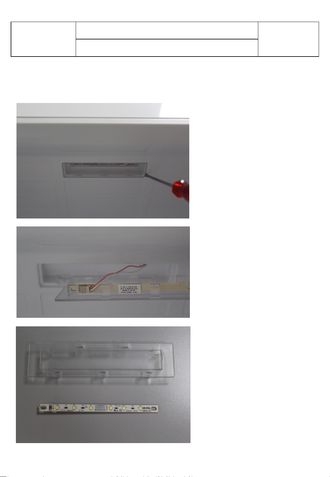
2. Remove the led strip light from its
housing. (Pic-2)
3. Disconnect the connector and change the
led light strip. (Pic-3)
1. Stick a tape to protect plastic. Insert a flat
screwdriver into the gap and remove the cover.
(Pic-1)
Picture-1
Picture-2 Picture-3
Replacement Led and Led Cover
ASSEMBLE & DISASSEMBLE
2795-ELECTRONIC
SEPTEMBER 2021
9
Remove the led cover by pulling forward and disconnect the connector.
ASSEMBLE & DISASSEMBLE
Replacement Top Led and Led Cover

2795-ELECTRONIC
NOVEMBER 2016
99
Replacement Head Panel and Main Board
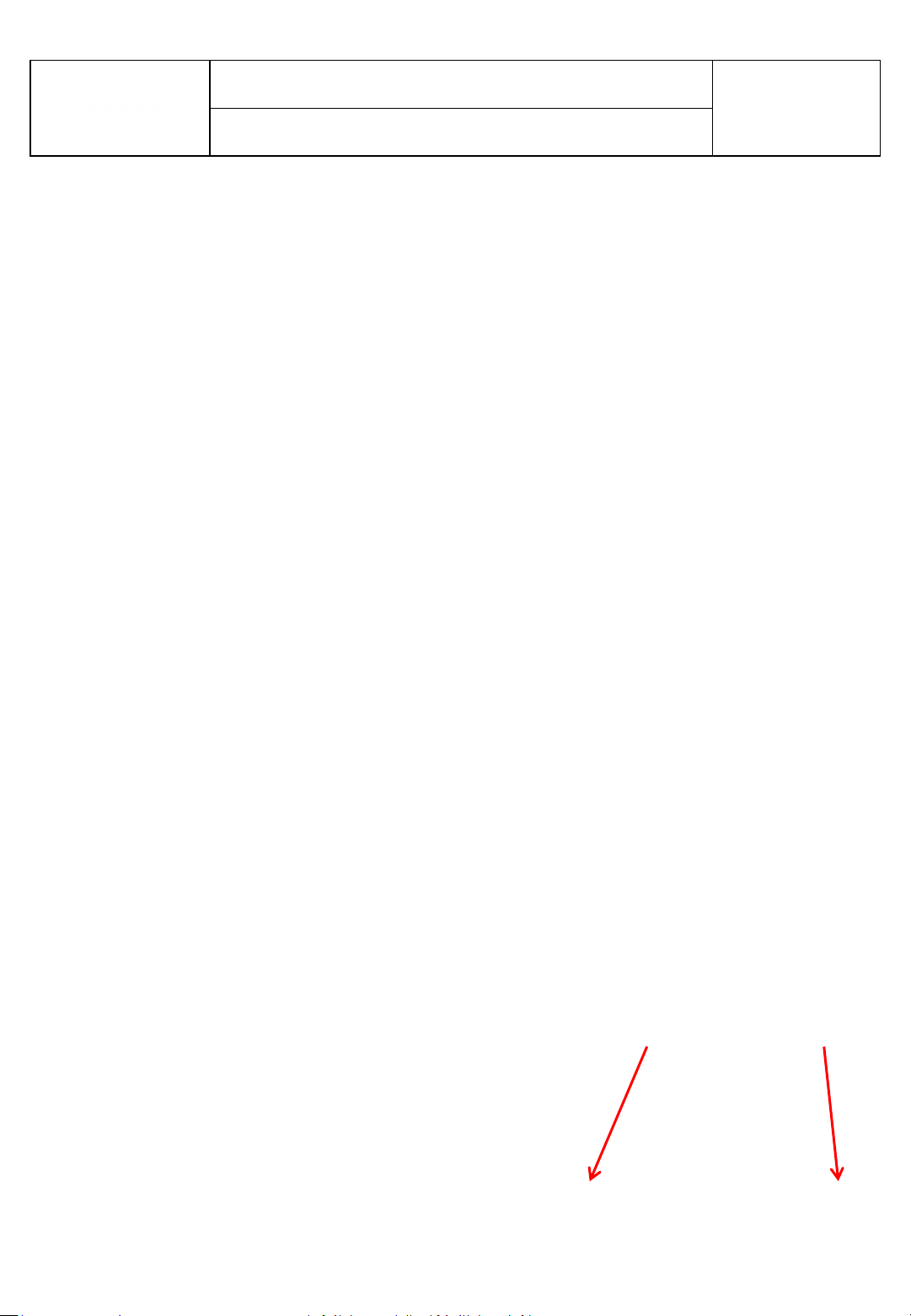
1. First remove cover by pulling leftward as
shown below.
ASSEMBLE & DISASSEMBLE
2. Remove other cover by pulling backward
from top side of the cover as shown below
1
3
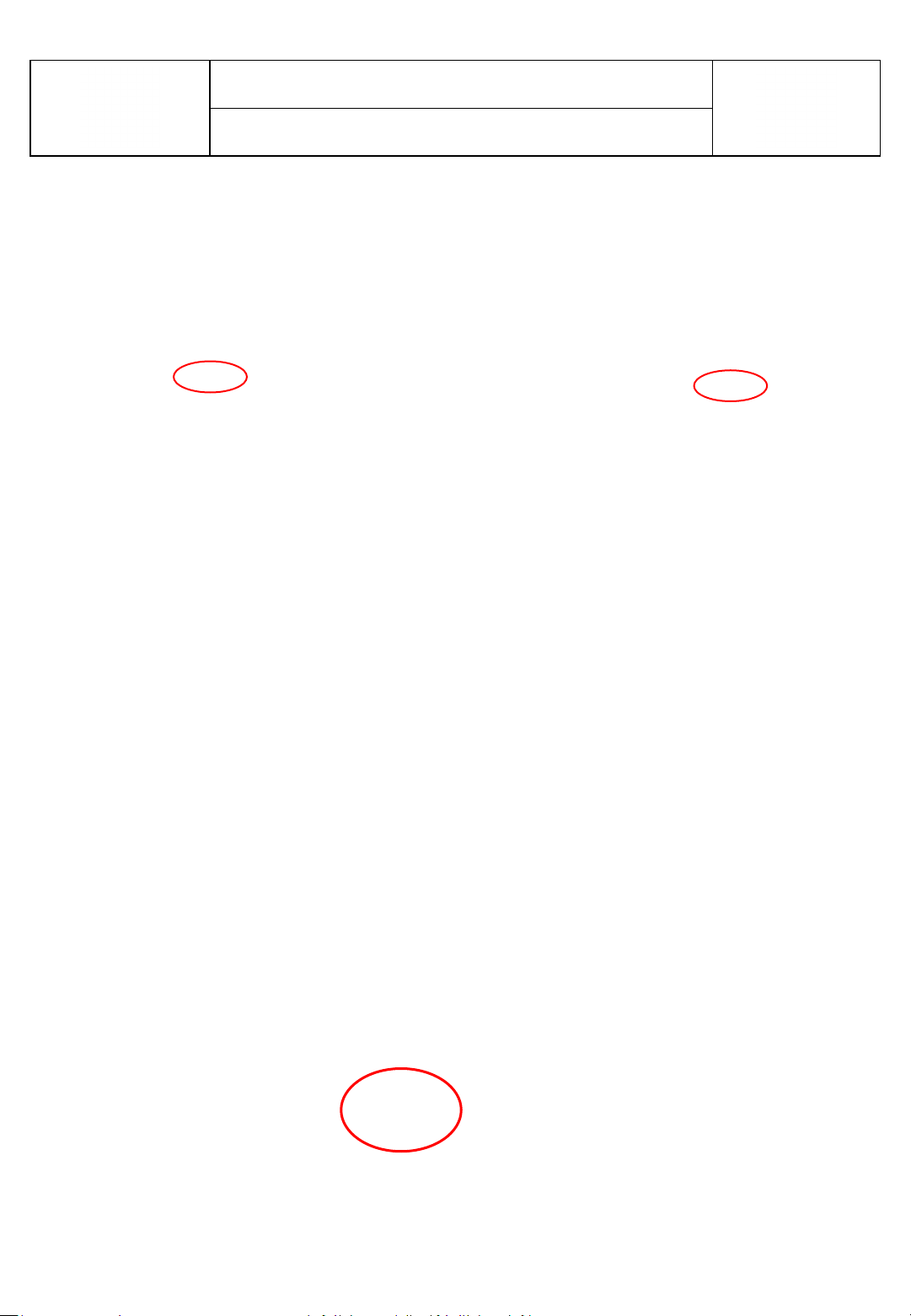
3. Unscrew screws marked with red circle at the picture below.
2795-ELECTRONIC
NOVEMBER 2016
10
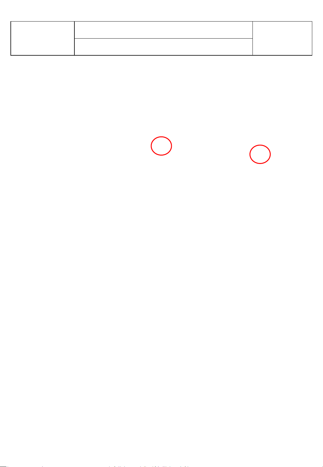
4. Disassemble snapfits at the area marked with red circle at the picture below .
It can be used any suitable tool to disassemble.
ASSEMBLE & DISASSEMBLE
5. Unplug socket on the board assembled head panel.

2795-ELECTRONIC
NOVEMBER 2016
11
6. To reassemble head panel ; first plug socket mentioned before and then place detail on
the head panel to related detail on the cover and then push head panel to place snapfits
marked with red circle below.
Detail on the cover
Snap-fit
ASSEMBLE & DISASSEMBLE
2795-ELECTRONIC
NOVEMBER 2016
12
7. Then screw head panel with screwdriver and assemble covers and complete head
panel assembly.
ASSEMBLE & DISASSEMBLE
8. Pull cover backward and remove from housing

2795-ELECTRONIC
NOVEMBER 2016
13
ASSEMBLE & DISASSEMBLE
9. Then unplug all sockets.
10. To reassemble cover first plug all sockets related place on the board.
2795-ELECTRONIC
NOVEMBER 2016
14
11. To reassemble cover pay attention to assemble with right direction. Details on the cover
and housing should be matched eachother
Housing
Cover
ASSEMBLE & DISASSEMBLE
Table of contents
Popular Control Panel manuals by other brands


TIS
TIS LUNA-9GANGS installation manual

HEATSTRIP
HEATSTRIP Heatstrip TT-MTM Operation, installation & maintenance instructions

Systemline
Systemline S6 user guide

Philips
Philips Color Kinetics Power/Data Supply SPDS-60CA... installation guide

U-Prox
U-Prox MP user manual

Valley
Valley ClassicPlus owner's manual