Sohal RX 400 User manual

MIG / MAG
MANUAL
RX 250 / RX 400
April, 2007

INDEX:
About Mig.
Advantages of Mig.
Brief description of all parts.
Setting welding current.
Problems and their solutions.
Cause of welding defects and
their solutions.
Technical information.
Circuit diagram of power source.
Circuit diagram o wire feeder.
Torch spare guidelines AK25-P
Torch spare guidelines 36KD-P
Installation guide.
3
3
4- 8
9
10
11
12
13
14
15
16
17
2

ABOUT MIG:
MIG (Metal Inert Gas) welding, also sometimes called GMAW (gas
metal arc welding), is a welding process that was originally developed
back in the 1940's. MIG welding is a semi automatic process in which a
relatively thin wire is feed through welding gun instead of using a flux
coated electrode. The wire fed continuously by a wire feeder from a coil
and a shielding gas is used as an alternate of flux, this mechanism gives
continuous non stop weld and many advantages comprising electrode
welding. Originally Argon was used for shielding the weld pool. This inert gas
acts as a shield, keeping air borne contaminants away from the weld zone.
Due to high cost of Argon, the weld process was modified by replacing
Argon with CO2, because this is active gas some amount of Mn and Si was
added to welding wire for cancelling the poor effect of CO2 on weld pool.
Today ‘s MIG wire is actually MAG(metal active gas ) wire. So, the name
MIG/MAG welding be famous.
The primar y advantage of MIG welding is that it allows metal to be
welded much quicker, slag free and continuous than traditional welding
"stick welding" techniques. Some major advantages of MIG are listed
below:
* It produces long continuous welds.
* Welds much faster, 3 to 5 times faster.
* No slag formed during welding.
* No need to chip or brush welding.
* Clean weld with very little spatter.
* Easy machinable softer welds.
* No burn out at bead corners.
* Great metal filling speed.
* Ideal for thin metal welding.
* Good finish.
ADVANTAGE OF MIG:
3

BRIEF DESCRIPTION OF ALL PARTS:
1
2
3
4
5
6
7
8
9
10
11
12
13
14
15 16
17
18
19
20
FRONT
4

31
32
33
34
35
36
37
38 39
40
REAR
BRIEF DESCRIPTION OF ALL PARTS:
5

POWER INDICATOR: It is placed in front of wire feeder shows the power is
on from power source and control cord to wire feeder has been
connected.
GAS CHECK: Press Gas check push button to check the flow of shielding
gas on conical nozzle and scaling on flow meter.
WIRE CHECK: Press Wire check push button to check the motor rotation
and for feeding wire in torch when you change an empty wire roll with
new one.
WIRE SPEED: This is knob to set a wire feed speed according to welding
volts and for control of welding current, To run motor fast or want to
increase in welding current rotate it clock wise and vice-versa. The
rotating device below knob is called potentio meter.
GAS PLUG: Connect the torch gas pipe here. When gas check or torch
trigger is pressed the gas comes from this plug and passes to welding
end of torch.
TORCH PLUG: This is base plug for the plug that is attached with torch,
make the connections by connecting these plugs. When you press
torch trigger the trigger switch works through this plug if this plug is not
connected torch switching will not work.
Feeder Motor: This is variable speed motor attached with a feed roll and
gearbox. It feeds wire at a constant speed set from wire speed knob.
CENTRAL ADAPTOR PM-3b: It’s the connector to connect welding torch,
Mig wire and welding current runs through this connector.
VOLT METER: By pressing OCV CHECK switch in front of power source, It
shows the open circuit volts of power source and when you do the
welding it shows welding volts.
AMPERE METER: It shows welding current during welding.
OCV CHECK: Press this toggle to check the set value of OCV(open
circuit volts).
POWER ON: Power on toggle switch. It is used for switching power source
control circuit and wire feeder ON or OFF. By switch off machine from
this switch does not mean the power is removed from power source, it
only cuts power of control circuit.
1.
2.
3.
4.
5.
6.
7
8.
9.
10.
11.
12.
6

POWER LED: It shows power is connected to machine and POWER ON
toggle switch is set to on.
WELD LED: The weld led shows the status of welding volts, when OCV
CHECK toggle switch or torch trigger is pressed will glow.
COURSE CONTROL SWITCH: It is 3-POLE 4-WAY rotary switch, It’s one step
increment make increase in OCV about 5-Volts.
FINE CONTROL SWITCH: It’s function is same as course control switch, the
only difference is it’s step size, a step of it will only change in OCV about
2-Volts.
WIRE FEEDER TERMINAL: Terminal for connecting wire feeder welding
lead. It is positive terminal.
WORK TERMINAL: It is negative terminal and connected to workpiece or
work table through a work lead.
WIRE FEEDER CONTROL PLUG: Connect one side Plug of 3 Core
connection lead here and other plug on the back of wire feeder.
Through these connection power is provided to wire feeder and to
make control between wire feeder and power source.
AIR VENT: This is out-let for cooling air at bottom of machine, keep the
surface clean below it, to prevent air blockage
WIRE SPOOL PIN: This pin is for fixing wire spool. Note that it could not
rotate freely, a tensioning spring is placed inside it.
CONTROL PLUG: A already mentioned connect control lead plug here.
GAS IN-LET: Connection for shielding gas.
HOLDER CABLE IN-LET: A welding cable has gone inside from here to
give positive current for torch. It’s other end is connected to Wire feeder
terminal.
HEATER PLUG: Connection for CO2 heater plug.
FUSE FOR CONTROL TRANSFORMER: This is fuse holder and a fuse inside
in protects control transformer from faulty conditions.
FUSE FOR FAN: Fuse for cooling fan.
13.
14.
15.
16.
17.
18.
19.
20.
31.
32.
33.
34.
35.
36.
37.
7

FUSE FOR HEATER: To protect heater supply from short circuit, in caseif
heater cable or heater gets faulty.
COOLING FAN: Give forced air in machine to cool DIODES and MAIN
TRANSFORMER.
SUPPLY COVER: It protects surrounding from touch with terminal strip
behind it. After connecting power supply place the cover back in its
original position.
38.
39.
40.
8

ST EP N O.
COU RSE F INE
OCV
1
1
1
1
2
2
2
2
3
3
3
3
4
4
4
4
1
2
3
4
1
2
3
4
1
2
3
4
1
2
3
4
22.8
23.7
24.7
25.7
26.3
27.6
28.7
29.9
30.9
32.5
34.3
36.1
37.4
39.7
42.0
44.5
Setting welding current:
* The values shown in table are only for guidelines.
Actual value may differ from table.
18
18.3
18.5
18.9
19.3
19.5
19.8
20.6
21.5
22
22.5
23
23.5
24
25
26
60
65
70
75
85
95
105
115
130
145
160
175
190
210
230
250
WE LD I NG
VOLTS
WE LD I NG
CU RR E NT
MIG RX 250
MIG RX 400
ST EP N O.
COU RSE F INE
OCV
1
1
1
1
2
2
2
2
3
3
3
3
4
4
4
4
1
2
3
4
1
2
3
4
1
2
3
4
1
2
3
4
WE LD I NG
VOLTS
WE LD I NG
CU RR E NT
9
27.5
28.5
29.5
30.8
31.6
32.9
34.3
35.8
36.8
38.4
40.2
42.3
43.8
46.1
48.8
51.5
20.0
20.3
21.2
21.5
21.4
22.3
23.8
23.9
23.6
24.4
26
26.9
27.6
29.6
30.7
32.4
100
130
140
160
180
200
200
220
250
260
280
300
320
340
360
380

PROBLEMS & THEIR Solutions:
Problem Cause Solutions
Power indicator does not
glow.
Wire feeder’s power
indicator does not glow or
it is not functioning.
Torch switch does not
work, But wire & gas Push
buttons on wire feeder are
working.
By pressing torch switch
Gas does not come.
Wire dose not come.
Current does not come.
While setting voltage from
rotary switches, voltage
variation is not linear.
One phase or all three
phases of power are
missing.
Faulty PCB.
Dust in torch switch or
loose connection of torch
plug.
Gas cylinder empty or
Heater does not heat up or
Pressure regulator faulty or
gas pipe blocked or faulty
solenoid valve.
Wire coil jam or Pressure
lever loose or Motor not
running.
Breakage of control
cable.
Loose wire on switch.
Damaged contacts of
switch.
Three core control cable
damage.
Melted fuse of PCB.
Check power supply status
then check fuses then
check supply cable &
connection strip at back
of machine.
Replace control cable.
Replace Fuse.
Replace PCB.
Wash the torch switch with
a oil based cleaning
agent or replace switch.
Replace torch plug.
Check step by step all
causes and replace the
faulty component.
Grease wire spool or set
appropriate pressure on
wire by adjusting pressure
lever then check motor if
faulty replace it else
replace PCB.
Find breakage area and
repair it or replace it with
new cable.
Tighten the loose wire.
Replace rotary switch.
1.
2.
3.
4.
5.
6.
7.
10
*We provide this information to guide only a certified engineer, There is always risk of electric shock during
repair please don’t do it your self, always get services from a professional engineer or company.

Cause of Welding defects and their solution’s:
Welding defect Cause Solutions
Black burned welding
bead.
Proper color good welding
but some fine holes like
needle holes in welding.
Weld bead raise (hollow
from inside) in-between or
probably at the end of
welding.
Low penetration.
Thin sheet burns during
welding.
Improper shielding gas.
Wrong selection of
shielding gas.
High welding current.
Faulty shielding gas.
Poor quality welding wire.
Dust, oil or cutting oil on
job.
Wrong selection of
shielding gas.
Low welding current.
If gas heater does not
heat up replace it or
increase gas flow, shield
welding area from air flow.
Replace gas cylinder with
a cylinder from different
lot.
Replace wire with an old
lot of wire or change its
brand.
Clean the job.
If you are using argon
mixed gas, use Co2
shielding gas.
Increase welding current.
Use Argon mixed gas
instead of Co2.
Set the welding current to
a relative lower value, if it
is not possible increase
the welding speed.
1.
2.
3.
4.
5.
11

* NOTE : The information provided above may different from actual.
Rated input voltage
Supply voltage
Rated frequency
Phase
Rated power
Rated duty cycle
OCV
Output current
Type of transformer
Insulation class
400
+
_
415 10%
50
3
9.5/7.8
60
22~45
50~250
Double star
Class H
IT EM
400
+
_
415 10%
50
3
19.4/17.5
60
28~54
80~400
Double star
Class H
RX 250
RX 400
TECHNICAL INFORMATION:
MAIN TR ANSFORMER
Required MCB 16 Amp. 3P 25 Amp. 3P
Supply Cable 1.5 mm2 or 3/20 2.5 mm2 or 7/22
Cooling Fan
Heater
220V AC 150W
220V AC 80W
Feeder Motor 24V DC
Solenoid Valve
24V DC
24V DC 24V DC
Main Contactor
16 Amp. Coil24V AC 16 Amp. Coil24V AC
220V AC 150W
220V AC 80W
Diodes 150 N 40 150 N 40
OCV Selector Switches 3P 4W 16Amp. 3P 4W 25Amp.
Fuses Control Tr.
Fan
Heater
PCB 78C
2.5 Amp
1 Amp
1 Amp
5 Amp.
2.5 Amp
1 Amp
1 Amp
5 Amp.
Welding Lead 25 mm2 35 mm2
MODEL
12

CIRCUIT DIAGRAM OF MIG RX 250 POWER SOURCE
L3
415-V
415-V
1
1
2
2
3
3
4
4
C
C
P
PP
P
P
P
1/3
1/3
2/3
2/3
3/3
3/3
B
L2
L1
M1
+
+
+
_
_
M2
Shunt (75m V/300 Amp. )
AUTO
Tr.2
Tr.1
Tr.3
2 x 2Amp.
220-V
26-V
FAN1
Q0
50-V
300-A
Q1
Y
L1
A1
Cont.1
F1
A2
Sw4
5Amp.
R
Sw3
F2
F3
3 PIN HCL PLUG (1)
(TO WIRE FEEDER)
HEATER PLUG
(2)
1
1
3
3
2
2
Sw1(
(
½
3
Sw2(
(
½
3
Sw2(
(
½
3
Sw2(
(
½
3
Sw1(
(
½
3
Sw1(
(
½
3
13
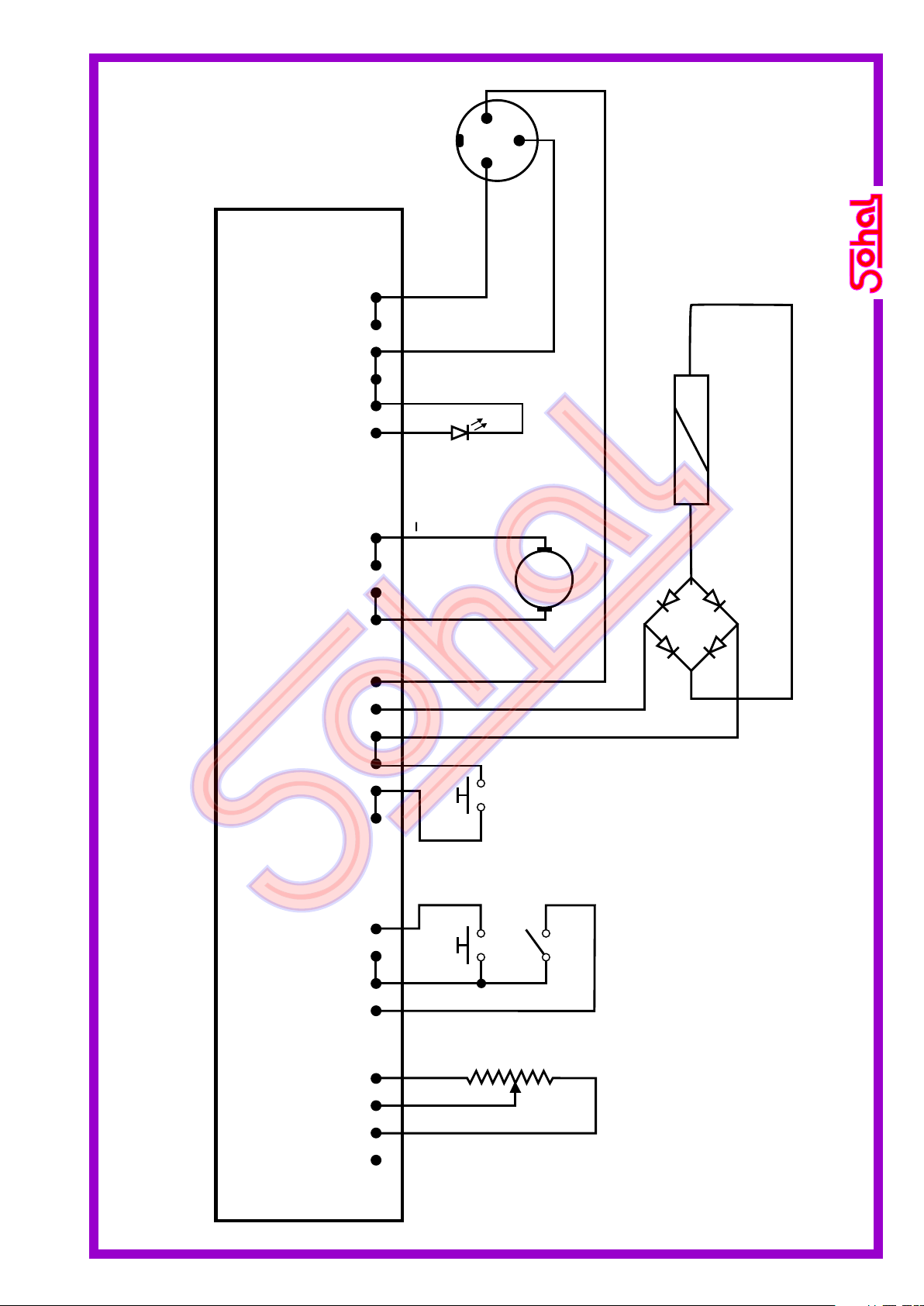
CIRCUIT DIAGRAM OF MIG RX 250 WIRE FEEDER.
Pot. 4K7 T. Sw.
P.B. (WIRE) P.B.
(GAS)
SOLENOID VALVE
COIL.
Arm.
+
1
2
3
3 PIN PLUG
(TO POWER SOURCE)
SOHAL 78 (PCB)
CN1CN2CN3CN4CN5
1 Amp.
14

Contact Tip
0.8 or 1.2mm
Contact Tip
Holder
Nozzle Spring
Swan Neck
Torch Body Plastic Ergo Handel with trigger
Trigger
Gas Nozzle
Liner Insulated
Power Cable 3m
Adaptor Nut Central
Adaptor
PM-3
Torch Plug
Gas Hose
28
8
90
M6
M6
M8
80
102
57
15
4
M8
1
M8
M 10x1
7
18
10
58
120
59
40
MIG TORCH SOHAL AK25-P
42
M 10x1
TORCH SPARE GUIDELINEs:
15

Contact Tip
0.8 or 1.2mm
Ergo Handel with trigger
Trigger
Gas Nozzle
Liner Insulated
Power Cable 3m
Adaptor Nut Central
Adaptor
PM-3
Gas Hose
Torch Plug
28
8
90
M6
M 10x1
18
10
58
120
59
40
MIG TORCH SOHAL 36KD-P
Contact Tip
Holder
Gas Diffuser
Swan Neck
80
16
M8
M6
28
70
32.5
M8
1
M 10x1
16
105
84
42
TORCH SPARE GUIDELINEs:
16

INSTALLATION GUIDE FOR MIG RX 250 / 400
17

Phone: +91-0161-2532255, Fax: +91-0161-2531116
SOHAL ELECTRIC WORKS
13243, Link Road, Chowk Dholewal, Ludhiana-141003 (PB.).
E-mail: mail@sohal.org
WWW.SOHAL.ORG
Other Sohal Welding System manuals

Popular Welding System manuals by other brands

ESAB
ESAB Precision Plasmarc EPP-600 manual

WIELANDER+SCHILL
WIELANDER+SCHILL WS 40 instruction manual

Miller
Miller Syncrowave 250 DX user manual

Thermal Dynamics
Thermal Dynamics cutmaster A60 operating manual

Kemppi
Kemppi MasterTig 535ACDC operating manual

Lincoln Electric
Lincoln Electric INVERTEC V160-S Service manual

Sonics
Sonics H520 T/E instruction manual

SIP
SIP P177 user manual

Rothenberger Industrial
Rothenberger Industrial ROXY KIT ECO manual

Timco Tools
Timco Tools iT500MIG Operation manual

Miller Electric
Miller Electric Big Blue 251D owner's manual

Lincoln Electric
Lincoln Electric POWER FEED 15M IM761 Operator's manual


