Cloos qineo PULSE MASTER-Plus User manual

Brief
instructions
and
Operating
instructions
MASTER-Plus
Operating Panel

ii MA_QN_MP
Carl Cloos Schweisstechnik GmbH
Industriestrasse 34 · D-35708 Haiger
Tel. +49 (0) 2773 85 - 0, Fax +49 (0) 2773 85 - 275
E-Mail: [email protected]
Internet: http://www.cloos.de
These instructions are only valid in combination with the
operating instructions for the welding machine.
Release date: 24.04.15
Keep for future use

Brief instruction
- MASTER Plus -
• Schematic design
• Basic settings for commissioning
Brief instructions Schematic design
Procedure for commissioning
1. Select current contact tube, drive rollers and core or liner
according to the filler metal.
2. Check current contact tube and welding torch connection
for solid fit.
3. Check wire drive rollers for cleanliness and correct fit.
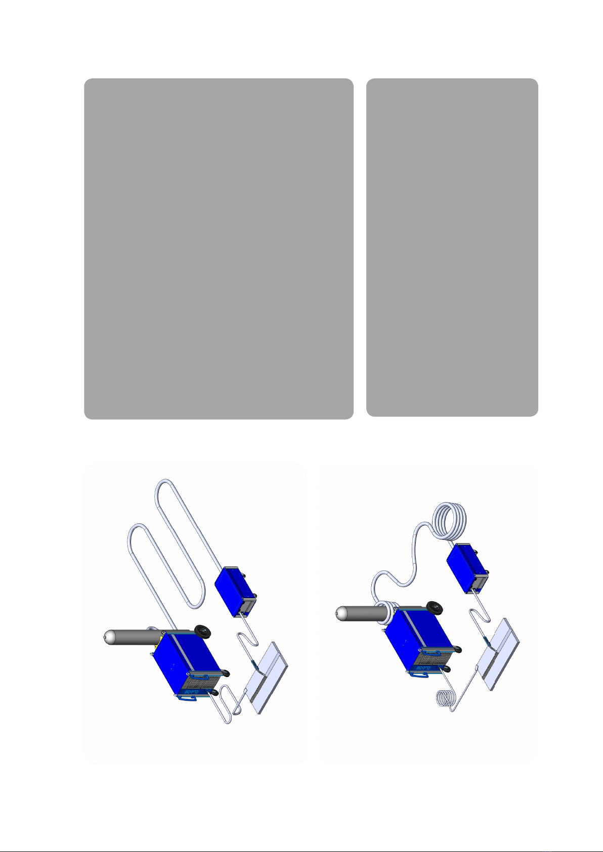
4. Lay connection cable assembly as shown at the top left.
5. Lay the earth cable as shown at the top left.
6. Check the earth cable on the welding machine and on the
workpiece / welding table for solid fit.
7. Adjust the correct gas flow rate.
8. Preselect the characteristic curve (see back).
Notice
Inductance effect
• The laying of the connection cable assembly and the
earth cable has a considerable effect on the welding char-
acteristics.
• Make sure that the connection cable assembly and the
earth cable are laid correctly and avoid coil windings (see
illustrations on the left).
Menu level
1
2 cycles
4 cycles
Super 4 cycles
Spot welding
External
1
5
43
2
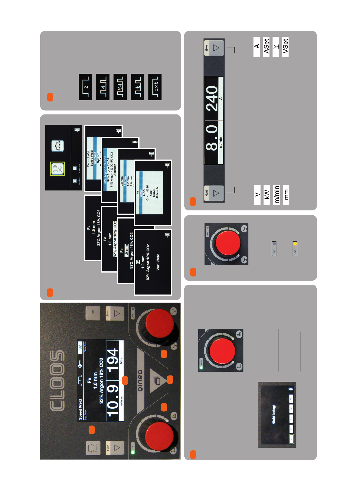
Select requested parameter and adjust by handwheel
Voltage ACTUAL value
Converted power
Wire feed
Sheet thickness preview
Current ACTUAL value
Current preview
Arc fine adjustment
Voltage preview
CAUTION: In synergy mode all other parameters will be auto-
matically adapted in the background.
Functions in the menu level:
• Turn handwheel: select
• Press handwheel: activate
Wire feed as
reference vari-
able
LED description
LED : Ready for operation
LED :Welding
LED : Failure
Press the
handwheel:
Open the job quick
memory menu
Save current setting:
- Select job No. (S1-S5)
- Press handwheel for 2 seconds
Delete welding job:
- Select job to be deleted
- Press handwheel for 4 seconds
Press
the handwheel
LED off:
Fine adjustment -
arc length
LED on:
Fine adjustment -
arc dynamics
Measured value display
5
Arc fine
adjustment
4
Adjust welding capacity
3
Select operating
mode
2
Brief instruction Basic settings for commissioning

For detailed information,
please refer to the operating manual!

7
Block 3c MASTER Plus Operating panel
Content
1. Structure and function ............................................................................ 9
1.1 Operating panel........................................................................................................ 9
1.2 Display.........................................................................................................................10
1.3 Hold value display..................................................................................................10
1.4 Description of operating modes .....................................................................11
1.4.1 Definition 2-cycles .............................................................................................11
1.4.2 Definition 4-cycles .............................................................................................11
1.4.3 Definition Super-4-cycles................................................................................11
1.4.4 Definition Spot welding/Interval................................................................11
1.4.5 Definition External ............................................................................................11
1.5 Description of processes.....................................................................................12
1.5.1 TIG Welding...........................................................................................................12
1.5.2 Electrode Welding..............................................................................................12
1.5.3 MIG/MAG Welding ............................................................................................12
1.6 Description of processes in MIG/MAG process.........................................12
1.7 Description of additional functions ..............................................................14
1.7.1 Duo Pulse...............................................................................................................14
1.7.2 Clean Start.............................................................................................................15
1.7.3 Diagnosis ...............................................................................................................15
2. Operation.................................................................................................. 16
2.1 Operating concept of the operating modes ..............................................16
2.1.1 Operating mode 2-cycles................................................................................16
2.1.2 Operating mode 4-cycles................................................................................17
2.1.3 Operating mode Super-4-cycles..................................................................18
2.1.4 Operating mode Spot welding/Interval ..................................................19
2.2 Configuration of characteristic curve...........................................................19
2.2.1 Adjust secondary parameters ......................................................................20
2.2.2 Restore original secondary parameters...................................................20
2.2.3 Parameter of operating modes "2-cycles" and "4-cycles" .................20
2.2.4 Additional parameters of operating mode "Super-4-cycles"..........21
2.2.5 Additional parameters of operating mode "Spot Welding/Inter-
val".............................................................................................................................21
2.3 Save and load job....................................................................................................22
2.3.1 Rapid memory access.......................................................................................22
2.3.2 Space management..........................................................................................23
3. Configuration operating panel............................................................. 27
3.1 Language ...................................................................................................................27
3.2 Basic settings ...........................................................................................................28
3.2.1 Basic screen...........................................................................................................28
3.2.2 2-cycles start and end crater program .....................................................28
3.2.3 Fine adjustment .................................................................................................28
3.2.4 Control voltage mode.......................................................................................29
3.2.5 External selection of process ........................................................................29

8MA_QN_MP
3.2.6 Reset to factory setting....................................................................................29
3.3 General configuration..........................................................................................29
3.3.1 Automatic Hold display...................................................................................29
3.3.2 MHW 405 TQ ........................................................................................................30
3.3.3 Cooling water pump.........................................................................................30
3.3.4 Job continuation.................................................................................................31
3.4 Compensation of the external welding circuit ........................................31
3.4.1 For software version x.05 or higher ...........................................................31
3.4.2 For software version x.10 or higher ...........................................................32
3.5 Process monitoring ...............................................................................................32
3.6 Cooling water monitoring .................................................................................34
3.7 Sense technology ...................................................................................................35
3.8 QWD PushPull..........................................................................................................35
3.9 Lock/unlock functions..........................................................................................36
3.9.1 Access management ........................................................................................37
3.9.2 User management and PAK ..........................................................................38
3.10 PC adaptation ..........................................................................................................43
3.11 Options .......................................................................................................................43
3.12 Activation code........................................................................................................43

9
1. Structure and function
1.1 Operating panel
Item Designation Function
Selection key Op-
erating modes
2 cycles, 4 cycles, Super-4 cycles, Spot weld-
ing, External
Job key Load, save, delete job
Hold key Actual value display: m/min, mm, V, kW
Display hold values
Rotary knob left Quick save selection (Jobs), setting the
capacity
Menu button Welding settings: Basic and secondary
parameters
Rotary knob right Fine adjustment, dynamics
Key button
Actual value display: A, ASet (power pre-
view), fine calibration or dynamic, VNomi-
nal (in Syn-Off mode), lock/unlock
12
3 4 5 6 7
Illustration 50. Master Plus Operating Panel
1
2
3
4
5
6
7

10 MA_QN_MP
Structure and function
1.2 Display
Item Designation Function
Process Display active processes
Operating mode Display active operating mode
Function lock Display locked functions active
Job number Display active job/rapid memory
Status display
LED:
Green - Welding power source switched on
Blue - Welding process runs
Red (blinking) - Error message
Red/blue (alternating) -
Error message while welding
Main display Display of the welding measurement values
Fine adjustment
LED on: Rotary knob (6) adjusts the dynamic
LED off: Rotary knob (6) adjusts the arc
length
1.3 Hold value display
The hold value display shows the averaged values for the last weld for
10 seconds. To activate the hold value display, press the Hold button until
the display changes.
After the welding process, the hold display will automatically be displayed
for 5 seconds. This function can be deactivated in the configuration menu
under "General".
Illustration 51. Master Plus Display
8
12
9 10 11
13 14
8
9
10
11
12
13
14

11
1.4 Description of operating modes
The following operating modes can be selected:
• 2 cycles
• 4 cycles
• Super 4 cycles
• Spot welding/Interval
• External
1.4.1 Definition 2-cycles
Operating mode 2-cycles is provided for short manual welds. You can find
additional information in the chapter 2.1 on page 16.
1.4.2 Definition 4-cycles
Operating mode 4-cycles is provided for short manual welds. You can find
additional information in the chapter 2.1 on page 16.
1.4.3 Definition Super-4-cycles
Operating mode Super-4-cycles is provided for longer standard manual
welding tasks. The operating mode allows working with different main
parameters for the so-called power continuation. The power continuation
is ensured by shortly pressing the torch button. You can find additional
information in the chapter 2.1 on page 16.
1.4.4 Definition Spot welding/Interval
The spot function allows spot welding for a defined time. You can find
additional information in the chapter 2.1 on page 16.
1.4.5 Definition External
This function is intended for automated or robotic operation.
The various signals are selected via the automation interface of the
welding power source.

12 MA_QN_MP
Structure and function
1.5 Description of processes
The following welding processes will be described hereunder.
1.5.1 TIG Welding
The process is provided with a Lift Start ignition.
• Use the left rotary knob to select the welding current.
The displays for wire diameter and shielding gas are hidden.
1.5.2 Electrode Welding
All common stick electrodes can be welded in operating mode Electrode.
If you selected the process Electrode, the right display shows "Aset". The
displays for the wire diameter and the material thickness are masked
out. You can now select the required welding current by means of the left
rotary knob.
By pressing the left rotary knob the open circuit voltage is switched on. The
status display is lit blue. By pressing the left rotary knob again or changing
into another operating mode the open circuit voltage is switched off.
1.5.3 MIG/MAG Welding
This process is divided into pulse-free and pulsed MIG/MAG welding pro-
cesses with and without synergy function, see following chapter.
1.6 Description of processes in MIG/MAG process
The following MIG/MAG welding processes can be selected at the welding
power source:
Process Function
Control Weld
(MAG normal)
Control Weld is a synergy-guided, pulse-free MAG
normal welding process.
Synergy Off
This MAG normal welding process is synergy-in-
dependent. The parameters for the wire feed and
welding voltage must be set individually using
the rotary knob.

13
Process Function
Rapid Weld (modified
Control Weld)
This is a modified standard characteristic curve
of "Control Weld". A very concentrated arc,
ensuring a very deep penetration, is generated.
Rapid Weld characteristic curves are available for
the following material-gas-wire combinations.
• Normal, Fe, 92% Ar, 8% CO2 wire 1,0 mm
• Normal, Fe, 92% Ar, 8% CO2 wire 1,4 mm
• Normal, Fe, 82% Ar, 18% CO2 wire 0,8 mm
• Normal, Fe, 82% Ar, 18% CO2 wire 1,0 mm
• Normal, Fe, 82% Ar, 18% CO2 wire 1,2 mm
• Normal, Fe, 82% Ar, 18% CO2 wire 1,6 mm
• Normal, Fe, 91% Ar, 4% O2 , 5% CO2 wire 1,2 mm
• Normal, Fe, 91% Ar, 4% O2 , 5% CO2 wire 1,4 mm
• Normal, Fe, 91% Ar, 4% O2 , 5% CO2 wire 1,6 mm
Vari Weld (I/I-Pulse)
The Vari Weld process is an I/I-controlled pulsed
arc.
The welding settings are selected for the
MIG/MAG welding process "Vari Weld" so an
extremely low spatter pulsed arc is created
without further fine adjustment (arc length and
dynamic).
The welding current does not depend on the
distance between torch and workpiece. Arc seam
tracking is not possible in connection with a
ROMAT robot application.
Speed Weld (U/I
Pulse)
The Speed Weld process is a U/I-controlled
pulsed arc.
The MIG/MAG welding process "Speed Weld"
is especially suitable for high welding speeds
and is ideal for joining sheet metal parts from
0,1 … 5 mm.
The welding current depends on the distance
between torch and workpiece. Arc seam tracking
in connection with a ROMAT robot application is
possible.

14 MA_QN_MP
Structure and function
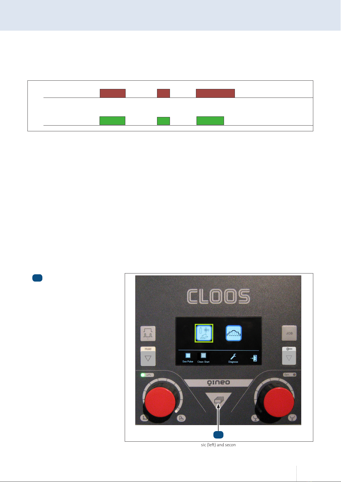
1.7 Description of additional functions
The following additional functions are available in the selection menu for
the basic and secondary parameters.
Function Condition
Duo Pulse only if the selected characteristic curve offers this func-
tion
Clean Start only if the selected characteristic curve offers this func-
tion
Diagnosis
1.7.1 Duo Pulse
A second weld parameter set is generated from the set basic value by
means of the Duo Pulse (Aluplus) function. This can be greater or less than
the basic value. By means of a defined frequency there is a switch-over
between the two parameter sets. The appearance of the weld seam surface
is formed by the defined change of parameters. During root welding,
defined cool-down times are reached depending on the setting.
If the "Duo Pulse" function is activated, the following additional changes
are available in the menu secondary parameters.
Parameters Value range
"DuoPulse modulation" Correction value (+/- 99)
"DuoPulse frequency" Correction value (+/- 99)
Menu button
1
Illustration 52. Selection menu for basic and secondary parameters
1

15
1.7.2 Clean Start
Clean Start is a special ignition routine which ensures a reliable and low
spatter arc ignition. The complete ignition routine runs in the millisecond
range.
1.7.3 Diagnosis
The machine model, performance class, data set number, the current
version of the selected synergy characteristic curve and the software
versions of the modules connected to the CAN bus are displayed in this
menu. The "Data set number" identifies the entire characteristic curve data
set. The "Characteristic curve number" identifies the current characteristic
curve.
Welding power sources are compatible with the operating panel with a
software version of x.08 and higher.

16 MA_QN_MP
Operation
2. Operation
2.1 Operating concept of the operating modes
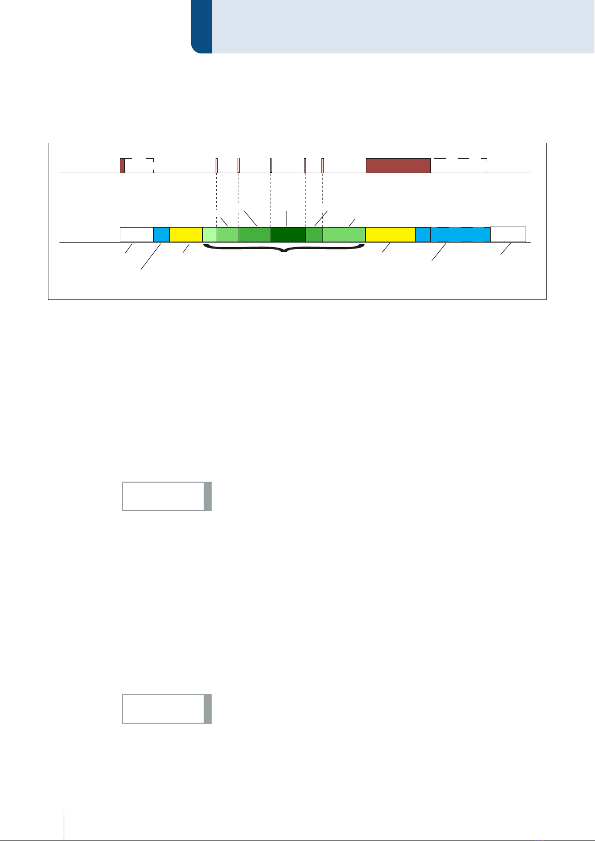
2.1.1 Operating mode 2-cycles
1st cycle --> Press and hold torch button
• Solenoid valve for shielding gas opens
• Weld voltage is applied on wire electrode
• Wire feed starts with reduced speed (inching-in)
• Arc ignites, weld current flows
• Wire feed switches to the preset speed
2nd cycle -->Release torch button
• Wire feed stops
• Weld voltage switches off after expiration of the "burnback time“
• Arc extinguishes
• Solenoid valve closes after expiration of the "gas post-flow time“
Torches
Keystroke
Welding time
Start time:
3 sec
Gas pre-flow +
inching in
Wire burnback +
gas post-flow
End crater
filling time:
3 sec
Upslope
1 sec
Downslope
2 sec
Main power
1 s
3 s 2 s 3 s

17
2.1.2 Operating mode 4-cycles
1st cycle --> Press and hold torch button
• Solenoid valve for shielding gas opens
• Weld voltage is applied on wire electrode
• Wire feed starts with reduced speed (inching-in)
• Arc ignites, weld current flows
• Wire feed switches to the preset speed
2nd cycle -->Release torch button
• The start program is executed with the adjusted parameters and then
switches via a programmable time function ("Up-Slope") into the main
program.
3rd cycle --> Press and hold torch button
• Change from main program to the end program via a time function
("Down-Slope").
4th cycle --> Release torch button
• Wire feed stops
• Weld voltage switches off after expiration of the "burnback time“
• Arc extinguishes
• Solenoid valve closes after expiration of the "gas post-flow time“
Torches
Keystroke
Welding time
Start time:
1 sec
Gas pre-flow +
inching in
Wire burnback +
gas post-flow
End crater
filling time:
3 sec
Upslope
3 sec
Downslope
2 sec
Main power
3 s1 s 2 s 3 s
18 MA_QN_MP
Operation
2.1.3 Operating mode Super-4-cycles
1st cycle --> Press and hold torch button
• Solenoid valve for shielding gas opens
• Weld voltage is applied on wire electrode
• Wire feed starts with reduced speed (inching-in)
• Arc ignites, weld current flows
• Wire feed switches to the preset speed
2nd cycle -->Release torch button
• The start program is executed with the adjusted parameters and then
switches via a programmable time function (Up-Slope) into the main
program.
If the start time in the program menu is set to "Torch", releasing the torch
button switches to the main program.
(optional) Power continuation --> Tap torch button
• Depending on the configuration of the "Step modulation" and "Num-
ber of steps" parameters, the power and wire feed speed are increased
or reduced with each press of the button on the torch. You can find ad-
ditional information in the chapter “2.2 Configuration of characteristic
curve”.
3rd cycle --> Press and hold torch button
• A time function (down-slope) switches from the main program to the
end program and the end parameters are executed.
4th cycle --> Release torch button
If the end crater filling time parameter is set to "Torch", the end param-
eters will not be executed until the torch button is released.
• Wire feed stops
• Weld voltage switches off after expiration of the "burnback time“
• Arc extinguishes
• Solenoid valve closes after expiration of the "gas post-flow time“
3 s
0 +4 +42 s
Torches
Keystroke
Welding time
Start time:
1 sec
End crater filling
time:Torch
Upslope
2 sec
Downslope
3 sec
Main power
Step modulation +2
Number of steps: 3
1 s +6
+2 +2 Torch
Gas pre-flow +
inching in Burnback +
Gas post-flow
Step 1
Step 1 Step 2 Step 3 Step 2
NOTICE!
NOTICE!
19
2.1.4 Operating mode Spot welding/Interval
Press and hold torch button
• Solenoid valve for shielding gas opens
• Weld voltage is applied on wire electrode
• Wire feed starts
• Arc ignites, weld current flows
• Welding process stops automatically after expiration of the defined
time.
Release torch button during the spot time
• The welding process is immediately stopped
2.2 Configuration of characteristic curve
The QINEO welding power sources always use the existing synergic
characteristic curves. These default values can be adjusted in the secondary
parameters menu.
2 s
Torches
Keystroke 1 s 3 s
2 s 2 s
1 s
Welding time
Menu button
1
Illustration 53. Selection menu basic (left) and secondary parameters (right)
1

20 MA_QN_MP
Operation
2.2.1 Adjust secondary parameters
1. Press the menu button.
2. Using the left rotary knob, select the menu for the secondary
parameters for the characteristic curve and confirm it by pressing the
knob.
3. Select the desired parameter by turning the left rotary knob and con-
firm your selection by pressing the knob.
4. Turn the rotary knob to change the default value and confirm the
correction value by pressing the knob.
5. To exit the menu, select the exit symbol by turning the rotary knob and
confirm by pressing the knob.
The correction values will be added to the original values. The parameters
of the original characteristic curve will not be changed.
2.2.2 Restore original secondary parameters
1. Press the menu button.
2. Using the left rotary knob, select the menu for the secondary
parameters for the characteristic curve and confirm it by pressing the
knob.
3. Set the correction value to "-0-".
4. To exit the menu, select the exit symbol by turning the rotary knob and
confirm by pressing the knob.
2.2.3 Parameter of operating modes "2-cycles" and "4-cycles"
• Gas pre-flow Correction value (Off, +/- 99)
• Inching-in Correction value (+/- 99)
• Start program (time) Correction value (Off, +/- 99)
• Start program (power) Correction value (+/- 99)
• Upslope Correction value (Off, +/- 99)
• Main power Absolute value (m/min)
• Downslope Correction value (Off, +/- 99)
• End crater prog. (time) Correction value (Off, +/- 99)
• End crater prog. (power) Correction value (+/- 99)
• Wire burnback Correction value (+/- 99)
• Gas post-flow Correction value (Off, +/- 99)
NOTICE!
Table of contents
Other Cloos Welding System manuals


Popular Welding System manuals by other brands


Panasonic
Panasonic YC-300BP2YAF operating instructions

Lincoln Electric
Lincoln Electric CV ADAPTER IM309-D Operator's manual

Cebora
Cebora MONO STAR MIG 1620/M instruction manual

Draper
Draper MW180AT instructions

Lincoln Electric
Lincoln Electric INVERTEC IM526-B Operator's manual

Miller
Miller ARC PAK 350 owner's manual


