manuals.online logo
Brands
  1. Home
  2. •
  3. Brands
  4. •
  5. STAMOS
  6. •
  7. Welding System
  8. •
  9. STAMOS S-MMA-250PI User manual

STAMOS S-MMA-250PI User manual

USER MANUAL | INSTRUKCJA OBSŁUGI | NÁVOD K POUŽITÍ | MANUEL D‘UTILISATION | ISTRUZIONI D`USO | MANUAL DE INSTRUCCIONES
BEDIENUNGSANLEITUNG
expondo.de
S-WIGMA 200P UK
S-MMA-250-PI UK
EN EN
Rev. 15.03.2021 Rev. 15.03.20212 3
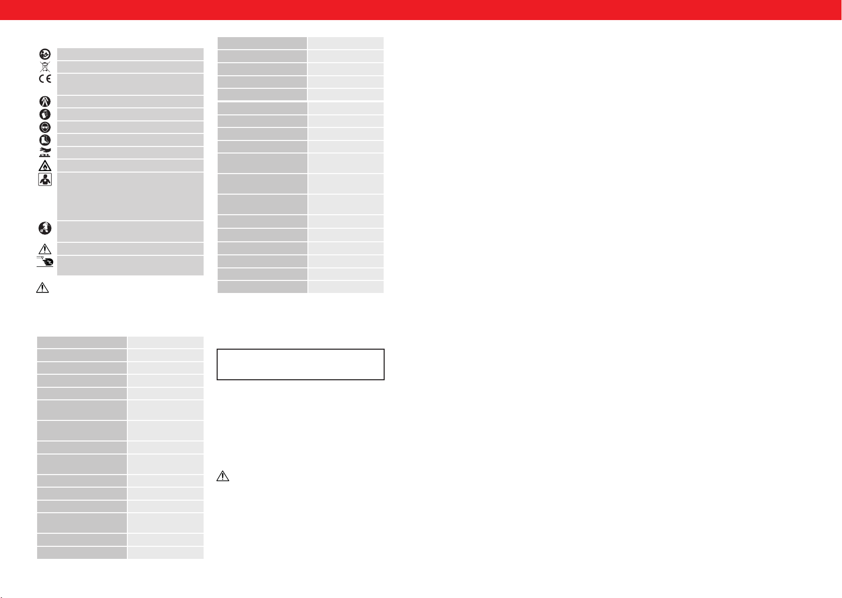
Parameter S-WIGMA 200P UK
Supply voltage (V) AC 230 V±10%
Frequency (Hz) 50
TIG DC welding current [A] 5 – 200
MMA welding current [A] 5 – 200
Welding current at 100%
duty cycle [A]
154
Welding current at 60% duty
cycle [A]
200
Pulse current [A] 5 – 200
Pulse frequency in DC mode
[Hz]
0,5 – 25
Gas post-ow time [s] 3
Current down slope [s] 0 – 5
TIG electrode diameter [mm] 1 – 3,2
MMA electrode diameter
[mm]
1 – 4
TIG ignition HF
ARC FORCE 
USER MANUAL
The operation manual must be read carefully.
The product must be recycled.
Satises requirements of applicable safety
standards
Use full body protective clothes.
ATTENTION! Wear protective gloves.
Safety goggles must be worn.
Protective footwear must be worn.
ATTENTION! Hot surface may cause burns.
ATTENTION! Risk of re or explosion.
ATTENTION! Harmful fumes, danger of
poisoning. Gases and vapours may be hazardous
to health. Welding gases and vapours are
released during welding. Inhaling these
substances may be hazardous to health.
Use a welding mask with appropriate lter
shading.
CAUTION! Harmful welding arc radiation.
Do not touch the parts that are under voltage/
power.
PLEASE NOTE! Drawings in this manual are for
illustration purposes only and in some details may
dier from the actual product.
The original operation manual is in German. Other
language versions are translations from German.
1. TECHNICAL SPECIFICATIONS
Parameter S-MMA-250-PI UK
Supply voltage (V) AC 230 V±10%
Frequency (Hz) 50
MMA welding current [A] 20 – 250
Welding current at 100%
duty cycle [A]
220
Welding current at 80% duty
cycle [A]
250
MMA electrode diameter
[mm]
1-4
ARC FORCE 
HOT START 
ANTI STICK 
Insulation class F
Protection class IP21S
Weight (kg) 5,6
2. GENERAL DESCRIPTION
The user manual is designed to aid safe and troublefree
use. The product is designed and manufactured in
accordance with strict technical guidelines, using state of
the art technologies and components and in compliance
with the most stringent quality standards.
DO NOT USE THE DEVICE UNLESS YOU HAVE
THOROUGHLY READ AND UNDERSTOOD THE
PRESENT USER MANUAL.
To extend the shelf life of the device and to ensure
trouble free operation, use it and perform maintenance
tasks in accordance with this user manual. The
technical data and specications in this user manual
are current. The manufacturer reserves the right to
make changes associated with quality improvements.
Taking into account technological progress and noise
reduction opportunities, the device was designed
to reduce noise emission risk to the minimum.
3. SAFETY OF USE
3.1. GENERAL NOTES
• Take care of your own safety and the one of
third parties by reading and strictly following the
instructions, included in the operating manual of the
device.
• Only qualied and skilled personnel can be allowed to
start, operate, maintain and repair the machine.
• The machine must never be operated contrary to its
intended purpose.
ATTENTION! Read all safety warnings and all
instructions. Failure to follow the warnings and
instructions may result in an electric shock, re and/
or serious injury or death.
HOT START 
ANTI STICK 
Insulation class F
Protection class IP21S
Weight (kg) 13,15
3.2. PREPARATION OF WELDING WORK SITE
WELDING OPERATIONS MAY CAUSE FIRE OR
EXPLOSION!
• Strictly follow the occupational health and safety
regulations applicable to welding operations and
make sure to provide appropriate re extinguishers
at the welding work site.
• Never carry out welding operations in ammable
places that pose the risk of material ignition.
• Never carry out welding operations in an atmosphere
containing ammable particles or vapours of
explosive substances.
• Remove all ammable materials within 12 meters
from the welding operations site and if removal is
not possible, cover ammable materials with re
retardant covering.
• Use safety measures against sparks and glowing
metal particles.
• Make sure that sparks or hot metal splinters do
not penetrate through the slots or openings in the
coverings, shields or protective screens.
• Do not weld tanks or barrels that contain or have
contained ammable substances. Do not weld in the
vicinity of such containers and barrels.
• Do not weld pressure vessels, pipes of pressurised
installations or pressure trays.
• Always ensure adequate ventilation.
• It is recommended to take a stable position prior to
welding.
3.3. PERSONAL PROTECTION EQUIPMENT
ELECTRIC ARC RADIATION CAN CAUSE DAMAGE TO
EYES AND SKIN!
• When welding, wear clean, oil stain free protective
clothing made of non-ammable and nonconductive
materials (leather, thick cotton), leather gloves, high
boots and protective hood.
• Before welding remove all ammable or explosive
items, such as propane butane lighters or matches.
• Use facial protection (helmet or shield) and eye
protection, with a lter featuring a shade level
matching the sight of the welder and the welding
current. The safety standards suggest colouring
No. 9 (minimum No. 8) for each current below 300
A. A lower shield colouring can be used if the arc is
covered by the workpiece.
• Always use approved safety glasses with side
protection under the helmet or any other cover.
• Use guards for the welding operation sites in order
• to protect other people from the blinding light
radiation or projections.
• Always wear earplugs or another hearing protection
to protect against excessive noise and to avoid
spatter entering the ears.
• Bystanders should be warned to not look at the arc.
3.4. PROTECTION AGAINST ELECTRIC SHOCK
ELECTRIC SHOCK CAN BE LETHAL!
• The power cable must be connected to the nearest
socket and placed in a practical and secure position.
Positioning the cable negligently in the room and on
a surface which was not checked must be avoided, as
it can lead to electrocution or re.
• Touching electrically charged elements can cause
electrocution or serious burns.
• The electrical arc and the working area are electrically
charged during the power ow.
• The device’s input circuit and inner power circuit are
also under voltage charge when the power supply
is turned on.
• The elements under the voltage charge must not be
touched.
• Dry, insulated gloves without any holes and
protective clothing must be worn at all times.
• Insulation mats or other insulation layers, big enough
as not to allow for body contact with an object or the
oor, must be placed on the oor.
• The electrical arc must not be touched.
• Electrical power must be shut down prior to cleaning
or electrode replacement.
• It must be checked if the earthing cable is properly
connected or the pin is correctly connected to the
earthed socket. Incorrectly connecting the earthing
can cause life or health hazard.
• The power cables must be regularly checked for
damage or lack of insulation. Damaged cables must
be replaced. Negligent insulation repair can cause
death or serious injury.
• The device must be turned o when it is not in use.
• The cable mustn’t be wrapped around the body.
• A welded object must be properly grounded.
• Only equipment in good condition can be used.
• Damaged device elements must be repaired or
replaced. Safety belts must be used when working
at height.
• All ttings and safety elements must be stored in
one place.
• From the moment of turning on the release, the
handle end must be kept away from the body.
• The chassis ground must be mounted to the welded
element or as close to it as possible (e.g. to a work
table).
THE DEVICE CAN STILL BE UNDER VOLTAGE UPON
FEEDER DISCONNECTION!
• The voltage in the input capacitor must be checked
upon turning o the device and disconnecting it
from the power source. One must make sure that the
voltage value is equal to zero. Otherwise, the device
elements must not be touched.
3.5. GASES AND FUMES
PLEASE NOTE! GAS MAY BE LETHAL OR DANGEROUS
TO HUMAN HEALTH!
• Always keep a certain distance from the gas outlet
• When welding, ensure good ventilation. Avoid
inhaling the gas.
• Chemical substances (lubricants, solvents) must be
removed from the surfaces of welded objects as they
burn and emit toxic smokes under the inuence of
temperature.
• The welding of galvanised objects is permitted only
when ecient ventilation is provided with ltration
and access to fresh air. Zinc fumes are very toxic, an
intoxication symptom is the so-called zinc fever.
4. OPERATION
4.1. GENERAL NOTES
• The device must be applied according to its purpose,
with observance of OHS regulations and restrictions
resulting from data included in the rating plate (IP
level, operation cycle, supply voltage, etc.).
• The machine must not be opened as it will cause
warranty loss and, in addition, exploding. Unshielded
elements can cause serious injuries.
EN EN
Rev. 15.03.2021 Rev. 15.03.20214 5
13 14 12
1
5748
22 21 20 18
24
23
• the other way round is prohibited. Such a change can
result in regulator damage and serious injuries.
• Economical gas use extends the welding time.
5. DEVICE USE
S-WIGMA 200P UK
22 18
12
25 514
1
S-MMA-250-PI UK
1. On/o switch.
2. LED – Display.
3. STARTING CUR. - value of output current upon arc
striking.
4. PULSE FREQ - impulse frequency during PULS mode
welding.
5. WELDING CUR. – welding current.
6. PULSE WD - PULSE WIDTH - this is the relation of the
impulse duration to the impulse period.
7. BASE CUR. - current sustaining the arch in the PULS
mode.
8. POST TIME - gas post-ow time Function used in
order to cool down the weld and to protect it against
oxidation.
9. FALL TIME (Down Slope) - time over which the value
of the output current decreases from the welding
current value to the initial current value.
10. CRATER - FINAL AMP. - output current value prior to
welding completion.
11. CLEAN WD - percentage dierence of positive time
and negative current direction in a single period of
welding current.
12. THERMAL OVERLOAD CONTROL LAMP - in case of
overheating, the lamp lights up and the device is
switched o. Do not attempt to start welding again,
leaving the device with fans switched on. The lamp
switches o automatically after the device is cooled
down. Note the rated operating cycle.
13. Pulsation function switch-key.
14. Operation mode switch TIG / MMA.
15. “AC/DC SWITCH” – TIG welding is divided into AC
(alternating current) and DC (direct current) welding.
16. “4T/2T SWITCH” – when welding in TIG mode, the user
can select “2T” mode (without sustain) and “4T” mode
(with sustain).
17. Switch-key (Foot pedal).
18. Mass conduit connector.
19. Foot switch socket.
20. TIG control cable socket.
21. TIG current – gas socket.
22. MMA connection.
23. Gas connector.
24. Earthing = at the rear side of each and every welder
there is a bolt with earthing marking. Before starting,
the device has to be earthed with the conduit which
cross section can not be smaller than 6 mm.
25. Power supply indicator = after switching on the
machine, this control lamp lights-up.
• The producer does not bear any responsibility for
technical changes in the device or material losses
caused by the introduction of the said changes.
• In case of incorrect device operation, contact the
service centre.
• Louvers must not be shielded – the welder must
be positioned at 30 cm distance from the objects
surrounding it.
• The welder must not be kept under your arm or near
your body.
• The machine must not be installed in rooms with
aggressive environments, high dustiness and near
devices with high electromagnetic eld emission.
4.2. DEVICE STORAGE
• The machine must be protected against water and
moisture.
• The welder must not be positioned on heated
surfaces.
• The device must be stored in a dry and clean room.
4.3 CONNECTING THE DEVICE
4.3.1 CONNECTING THE POWER
• The connection of the device must be performer
by a qualied person. In addition, a person with
required qualications should check if the earthing
or electrical installation with protection system is in
line with the safety regulations and if they operate
correctly.
• The device must be placed near the work station.
• Connecting excessively long conduits to the machine
must be avoided.
• One-phase welders should be connected to the
socket tted with an earthing prong.
• Welders powered from a 3-Phase network are
delivered without a plug, the plug must be obtained
independently and installation should be assigned to
a qualied person.
PLEASE NOTE! THE DEVICE MAY ONLY BE USED UPON
CONNECTION TO AN INSTALLMENT WITH A PROPERLY
FUNCTIONING FUSE.
4.3.2 CONNECTING GAS
• Gas tanks must be placed far from the welded object
and be protected against falling.
• Gas connector of the welder must be connected with
the tank or gas installation by means of the correct
pipe and regulator with gas ow regulation. Please
note! Connection of line regulators to the tank and
1
3
4
5
6
2
1. Long cap, rear
2. Short cap, rear
3. Collet
4. Blowpipe handle
5. Collet in housing
6. Ceramic nozzle
6. DISPOSING OF PACKAGING
The various items used for packaging (cardboard, plastic
straps, polyurethane foam) should be kept, so that the
device can be sent back to the service centre in the best
possible condition in case of any problems!
7. TRANSPORTATION AND STORAGE
Shaking, crashing and turning upside down of the device
should be prevented while it is transported. Store it in a
properly ventilated surrounding with dry air and without
any corrosive gas.
8. CLEANING AND MAINTENANCE
• Disconnect from electricity when cleaning
equipment.
• Use cleaner without corrosive substances to clean
surface.
• Dry all parts well after cleaning before the device is
used again.
• Store the unit in a dry, cool location, free from
moisture and direct exposure to sunlight.
9. REGULAR CONTROL OF THE DEVICE
Check regularly that the device doesn´t present any
damage. If there is any damage, please stop using the
device. Please contact your customer service to solve the
problem.
What to do in case of a problem?
Please contact your customer service and prepare following
information:
• Invoice number and serial number (the latter is to be
found on the technical plate on the device).
• If relevant, a picture of the damaged, broken or
defective part.
• It will be easier for your customer service clerk to
determine the source of the problem if you give
a detailed and precise description of the matter.
The more detailed your information, the better the
• customer service will be able to help you with your
problem rapidly and eciently!
CAUTION: Never open the device without the authorization
of your customer service. This can lead to a loss of warranty!
5.1. PREPARING THE DEVICE FOR USE / DEVICE USE
Each unit is equipped with a main power cable, which
is responsible for providing current and voltage to the
device. If the device is connected to power which exceeds
the required voltage, or if the wrong phase is set, it may
lead to severe damage to the unit. This is not covered
by the warranty for the equipment and the user will be
responsible for such situations.
5.2. TIG TORCH
Rev. 15.03.2021 Rev. 15.03.20216 7
NOTES/NOTIZENNOTES/NOTIZEN
expondo.de
Hersteller an Verbraucher
Sehr geehrte Damen und Herren,
gebrauchte Elektro – und Elektronikgeräte dürfen gemäß europäischer Vorgaben [1] nicht zum unsortierten Siedlungsabfall
gegeben werden, sondern müssen getrennt erfasst werden. Das Symbol der Abfalltonne auf Rädern weist auf die Notwendigkeit
der getrennten Sammlung hin. Helfen auch Sie mit beim Umweltschutz. Sorgen Sie dafür, dieses Gerät, wenn Sie es nicht mehr
weiter nutzen wollen, in die hierfür vorgesehenen Systeme der Getrenntsammlung zu geben.
In Deutschland sind Sie gesetzlich [2] verpichtet, ein Altgerät einer vom unsortierten Siedlungsabfall getrennten Erfassung
zuzuführen. Die öffentlich – rechtlichen Entsorgungsträger (Kommunen) haben hierzu Sammelstellen eingerichtet, an denen
Altgeräte aus privaten Haushalten ihres Gebietes für Sie kostenfrei entgegengenommen werden. Möglicherweise holen die
rechtlichen Entsorgungsträger die Altgeräte auch bei den privaten Haushalten ab.
Bitte informieren Sie sich über Ihren lokalen Abfallkalender oder bei Ihrer Stadt – oder Gemeindeverwaltung über die in Ihrem
Gebiet zur Verfügung stehenden Möglichkeiten der Rückgabe oder Sammlung von Altgeräten.
[1] RICHTLINIE 2002/96/EG DES EUROPÄISCHEN PARLAMENTS UND DES RATES
ÜBER ELEKTRO – UND ELEKTRONIK – ALTGERÄTE
[2] Gesetz über das Inverkehrbringen, die Rücknahme und die umweltverträgliche Entsorgung
von Elektro – und Elektronikgeräten (Elektro – und Elektronikgerätegesetz – ElektroG).
Umwelt – und Entsorgungshinweise
For the disposal of the device please consider and act according to the national and local rules and regulations.
CONTACT
8
expondo Polska sp. z o.o. sp. k.
ul. Nowy Kisielin-Innowacyjna 7
66-002 Zielona Góra | Poland, EU
e-mail: info@expondo.de

This manual suits for next models

1

Other STAMOS Welding System manuals

STAMOS SWJ02M User manual

STAMOS

STAMOS SWJ02M User manual

STAMOS S-ALU 200 User manual

STAMOS

STAMOS S-ALU 200 User manual

STAMOS Power2 S-MIG 100 User manual

STAMOS

STAMOS Power2 S-MIG 100 User manual

STAMOS S-Multi 41 User manual

STAMOS

STAMOS S-Multi 41 User manual

STAMOS AG60 User manual

STAMOS

STAMOS AG60 User manual

STAMOS S-LS-12 User manual

STAMOS

STAMOS S-LS-12 User manual

STAMOS S-PLASMA 55H User manual

STAMOS

STAMOS S-PLASMA 55H User manual

STAMOS S-WIGMA 180 User manual

STAMOS

STAMOS S-WIGMA 180 User manual

STAMOS POWER 2 S-ARC 160LT User manual

STAMOS

STAMOS POWER 2 S-ARC 160LT User manual

STAMOS S-MULTI 195 IGBT User manual

STAMOS

STAMOS S-MULTI 195 IGBT User manual

STAMOS RED-K TITAN User manual

STAMOS

STAMOS RED-K TITAN User manual

STAMOS S-PLASMA 55H UK User manual

STAMOS

STAMOS S-PLASMA 55H UK User manual

STAMOS S-MIGMA-155 User manual

STAMOS

STAMOS S-MIGMA-155 User manual

STAMOS S-MIGMA-250.IGBT User manual

STAMOS

STAMOS S-MIGMA-250.IGBT User manual

STAMOS POWER2 S-CUTTER 40PFC User manual

STAMOS

STAMOS POWER2 S-CUTTER 40PFC User manual

STAMOS Power2 S-MAG 180 User manual

STAMOS

STAMOS Power2 S-MAG 180 User manual

STAMOS S-Plasma 50 User manual

STAMOS

STAMOS S-Plasma 50 User manual

STAMOS S-MIG 250 User manual

STAMOS

STAMOS S-MIG 250 User manual

STAMOS S-MTM 220 UK User manual

STAMOS

STAMOS S-MTM 220 UK User manual

STAMOS S-AC 200P User manual

STAMOS

STAMOS S-AC 200P User manual

STAMOS Power 2 S-CUTTER 50 User manual

STAMOS

STAMOS Power 2 S-CUTTER 50 User manual

STAMOS S-STUD1600 User manual

STAMOS

STAMOS S-STUD1600 User manual

STAMOS S-WIGMA 200 PRO User manual

STAMOS

STAMOS S-WIGMA 200 PRO User manual

STAMOS Operator User manual

STAMOS

STAMOS Operator User manual

Popular Welding System manuals by other brands

Kemppi MinarcTig 180MLP Service manual

Kemppi

Kemppi MinarcTig 180MLP Service manual

Hypertherm MAX42 Service manual

Hypertherm

Hypertherm MAX42 Service manual

Magmaweld ID 250E user manual

Magmaweld

Magmaweld ID 250E user manual

Parkside PESG 120 B3 Assembly, operating and safety instructions, Translation of the original instructions

Parkside

Parkside PESG 120 B3 Assembly, operating and safety instructions, Translation of the original instructions

Miller Coolmate 3.5 CE owner's manual

Miller

Miller Coolmate 3.5 CE owner's manual

Leister WELDPLAST S2 operating instructions

Leister

Leister WELDPLAST S2 operating instructions

CEVIK EVOMAX 200 instruction manual

CEVIK

CEVIK EVOMAX 200 instruction manual

MK Welding Multi-GMAW 200 LCD PFC user manual

MK Welding

MK Welding Multi-GMAW 200 LCD PFC user manual

Lincoln Electric BIG RED 500 Operator's manual

Lincoln Electric

Lincoln Electric BIG RED 500 Operator's manual

Lincoln Electric POWER MIG 256 Operator's manual

Lincoln Electric

Lincoln Electric POWER MIG 256 Operator's manual

Lincoln INVERTEC PC 65 Operator's manual

Lincoln

Lincoln INVERTEC PC 65 Operator's manual

Miller RAD-400EF owner's manual

Miller

Miller RAD-400EF owner's manual

EINHELL CEN 151/2 operating instructions

EINHELL

EINHELL CEN 151/2 operating instructions

Miller DIMENSION NT 450 WCC owner's manual

Miller

Miller DIMENSION NT 450 WCC owner's manual

Orion c Series user manual

Orion

Orion c Series user manual

Chicago Electric 8878 Assembly and operation instructions

Chicago Electric

Chicago Electric 8878 Assembly and operation instructions

Bestarc BTC500 manual

Bestarc

Bestarc BTC500 manual

King Ultrasonic CO KWL3215 user manual

King Ultrasonic CO

King Ultrasonic CO KWL3215 user manual

manuals.online logo
manuals.online logoBrands
  • About & Mission
  • Contact us
  • Privacy Policy
  • Terms and Conditions

Copyright 2025 Manuals.Online. All Rights Reserved.