Sol-Reliant OG 300-2007026C User manual
Installation, Operation and Maintenance Manual
IMPORTANT: Please keep this manual on site
with the Sol-ReliantTM System
Electric Backup
Gas Backup
OG 300-2004008A (SR 56/80 E PVDB)
OG 300-2004008B (SR 40/80 E PVDB)
OG 300-2007015A (SR 56/120 SE PVDB)
OG 300-2007025A (SR 80/80 E PVDB)
OG 300-2007025B (SR112/80 E PVDB)
OG 300-2007025C (SR112/120 E PVDB)
OG 300-2004009A (SR 56/80 G PVDB)
OG 300-2004009B (SR 40/80 G PVDB)
OG 300-2007026A (SR 80/80 G PVDB)
OG 300-2007026B (SR112/80 G PVDB)
OG 300-2007026C (SR 112/120 G PVDB)

1
______________________________________________________________________________
0326 SW Pendleton St. Portland, OR 97239 www.SolReliant.com
(503) 866-6437
Thank you for choosing a Sol-ReliantTM solar hot water heating system. You have
invested in one of the most reliable and dependable solar water heating systems on the
market. It will serve you for decades and pay for itself over and over.
Beyond the economics, thousands of pounds of CO2 will NOT go into the Earth’s
atmosphere each year because you decided to go solar.
More than twice the hot water, less than half the cost, and environmentally friendly–
that’s the value of your Sol-ReliantTM solar water heating system.
Your system consists of the highest quality components to give you many years of
trouble-free performance.
This manual provides all the information related to the system and is intended to be
for the benefit and use of the original owner, future owners, and as a reference for
anyone who may be working on or around the system.
Please take a moment now to read page 3, Monitoring Your System, which explains
how easy it is to make sure your system is always functioning properly. It is very easy to
tell if the system is working.
Again, thank you for choosing Sol-Reliant. We appreciate your business. If you have
any questions, or if we can be of assistance in any way, please do not hesitate to
contact us.
2
TABLE OF CONTENTS
Monitoring Your System (Please read carefully)
3
System Diagram
4
How It Works
4
System Components
5
Installation Instructions
10
Pre-Installation Planning
10
Collector Installation Instructions – Rooftop Installation
11
Collector Mounting Diagrams
14
Solar Tank Installation Instructions
18
Potable Water Plumbing
18
Wiring Pump and Charging the Solar Loop
20
Storage Tank Installation, Use and Care Manual
22
Operation and Maintenance
34
Troubleshooting
35
Re-roofing
35
Optional Water Heater Timer (Single Tank Systems Only)
37
Sol-Reliant Manufacturer’s Warranty
38
System Component Spec Sheets and Warranties
39
Propylene Glycol MSDS Data Sheets
49

3
Monitoring Your System –Please Read Carefully
Once your system is fully operational, you can monitor it using two devices: the flow meter and
the temperature gauge. (See diagram on page 4 for location).
The flow meter is a visual site glass located near the top of the solar tank, and shows the current
flow rate of your system. With maximum sun, the circulation rate will be about 2.5 gallons per
minute. If there is no flow on a sunny day, or if there are excessive bubbles in the flow meter,
this could indicate a problem. However, if the system has reached high limit, indicated by the
temperature gauge being above 150 degrees F, it may have turned off automatically. For an
accurate reading, hot water should be turned “on” for a few seconds somewhere in the house to
move water from the solar tank past the temperature gauge.
The temperature gauge is located just above the solar storage tank, mounted on the “hot” pipe
returning to the solar tank from the solar collector (see diagram on page 4). The temperature
gauge shows the temperature of the heat transfer fluid as it is being heated by the sun. In order to
get an accurate reading, the pump must be in operation. NOTE: This gauge does not tell you the
internal temperature of the potable water within the solar storage tank. The temperature within
the storage tank will be 20-40 degrees cooler than the temperature gauge reading.
When leaving for extended periods in the summer or winter, there is no need to switch your
system off. (See Operation and Maintenance, page 34 and Troubleshooting, page 35.)
You should check your flow meter and temperature gauge at least once a month.
In case of emergency call your installer:
____________________________________
or Sol-ReliantTM at (503) 866-6437

4
System Diagram
All the components of your system are listed in the diagram below:
How It Works
Your system is closed loop, which means the solar heating components including the collector,
pump, heat exchange coil, and drain back reservoir are part of a closed circuit -– a closed circuit
separate from the potable water system. When the sun comes out, a photovoltaic (PV) powered
pump circulates the heat transfer fluid through the solar collector. The fluid gains heat and
travels from the roof to the heat exchanger coils located in the bottom third of your solar storage
tank. The solar-heated fluid warms the potable water in the tank before it continues back to the
solar collector, where it gains more heat and repeats the process. The solar-heated fluid warms
the potable water in the tank without contamination, safely isolated by an efficient, double-wall
heat exchanger. The heat transfer fluid is freeze-proof because it is a combination of food-grade
propylene glycol and water.
Before you had a solar system, the cold water from your water source went directly to your
existing electric or gas water heater (hereafter referred to as auxiliary water heater). Now it goes
to the bottom of the solar storage tank. The solar pre-heated water rises to the top of the tank due
to stratification (hot water rises; cold water moves to the bottom). The solar pre-heated water
then moves from the top of the solar storage tank to your auxiliary water heater whenever you
turn on the hot water. The more the sun pre-heats the water, the less energy is required by your
5
auxiliary water heater to bring the water in the tank up to the desired temperature. For instance, if
the water heater element is set at 120 degrees F, and the sun has already pre-heated the water to
120 degrees or above, the element will not come on at all. If the solar pre-heated water is less
than 120 degrees, the water heater element will turn on long enough to “boost” the temperature
up to the thermostat setting.
Your solar system is fully automatic. The 12-volt DC pump is powered directly by the 30-watt
photovoltaic (PV) module. The pump is self-regulating: the brighter the sun, the faster it pumps.
Even on cloudy days there will be some solar gain. If there is no sun, the pump has no power to
operate, and the system will be in a state of rest, or “drained-back.” The solar loop is not
pressurized. In the drained-back state, the thermal collector is empty. A length of 2” diameter
copper pipe located just below the collector acts as a reservoir tank and holds enough fluid to
keep the pump primed during circulation. With the pump off, the fluid drains back into the
reservoir tank by gravity. The propylene glycol in the system protects it from freezing.
System Components
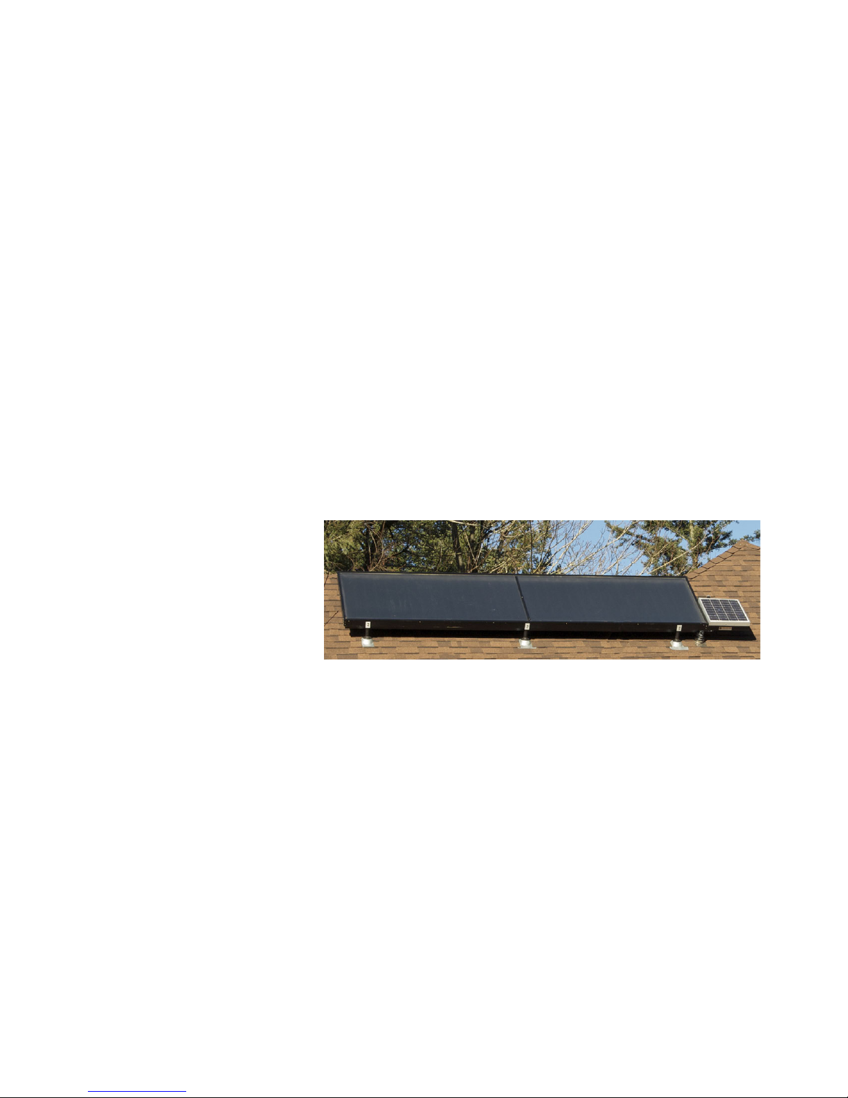
Collector
The Sol-Reliant solar thermal collector uses AET Thermafin absorber plates. These are all-
copper absorbers with a selective surfacing called Black Majic, which allows for optimum
absorption in sunny or cloudy weather. This special surfacing gives you 96% absorption when
light strikes the solar absorber
plate with less than 10% loss
through emissivity. The
absorbers are housed in an
anodized aluminum box,
insulated with high-
temperature rigid insulation
around the perimeter of the box
and on the underside of the absorber assembly. Low-iron, tempered glass allows the maximum
amount of sunlight to enter the collector (over 90%). Although we warranty these collectors for
six years, their real useful life can easily be 50 years or more.
Tank
Your solar storage tank is made by Rheem and has a capacity of either 80 gallons (Model #
81VR80HE-1) or 120 gallons (Model # 81VR120HE-1), depending on your system. It is
guaranteed for 6 years by Rheem. A DWP (double wall with leak protection) type heat
exchanger is coiled around the bottom one-third of the solar storage tank. The heat transfer fluid
circulates through the solar collector and heat exchanger, warming the potable water in the tank.
The solar storage tank, like your auxiliary water heater, is equipped with a sacrificial anode rod.
The purpose of this anode is to protect the tank from the minerals and aggressive chemical
elements in water that could reduce the life of your glass-lined stainless steel tank. The life of
both your storage tank and your auxiliary water heater can be extended considerably if anode
6
rods are changed every 10 years or whenever needed. Your local water bureau or well testing
agent can advise you if the anode should be changed more often.
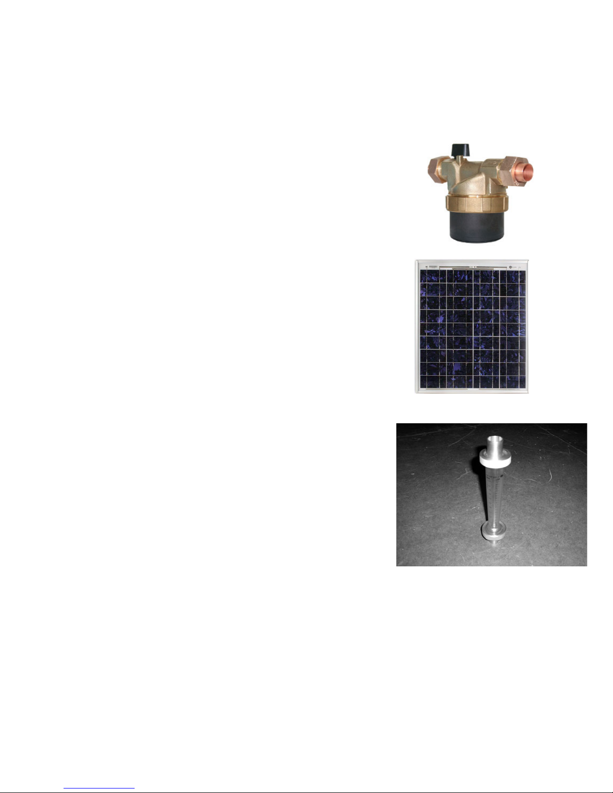
Pump and Control
The Sol-Reliant uses a 12-volt DC pump to circulate the heat
transfer fluid through the solar collector and heat exchanger. You
should expect to see a flow rate of 1-3 gallons per minute at the flow
meter, located on the plumbing of the solar storage tank (see below).
Your system is self-regulating because the pump is powered by a
photovoltaic module (pictured below). On bright, sunny days, the
pump will run at the maximum speed for your system. On overcast
days, the pump will run at a lower speed.
Photovoltaic (PV) Module
The 30-watt photovoltaic module collects energy from the sun to
power the pump (pictured above).
Flow Meter
The visual site glass located near the top of the solar tank shows
current flow rate of your system. The Pentair LDF 360B shows
flow from 0.5 gallon to 5 gallons per minute. With maximum
sun, the meter will show about 2.5 to 3 gallons per minute.
Temperature Gauge
Located just above the solar storage tank, mounted on the “hot” pipe between the solar tank
outlet and the inlet on the auxiliary water tank, the temperature gauge will tell you to what
temperature solar energy has pre-heated the water. In order to get an accurate reading, it is
necessary to turn on a hot water faucet for a few moments to let hot water move from the solar
tank past the temperature gauge. Other temperature gauge wells can be located on the solar
return line and the mixed or tempered hot water “out” line. You can get multiple readings from
one gauge by moving it from well to well.
7
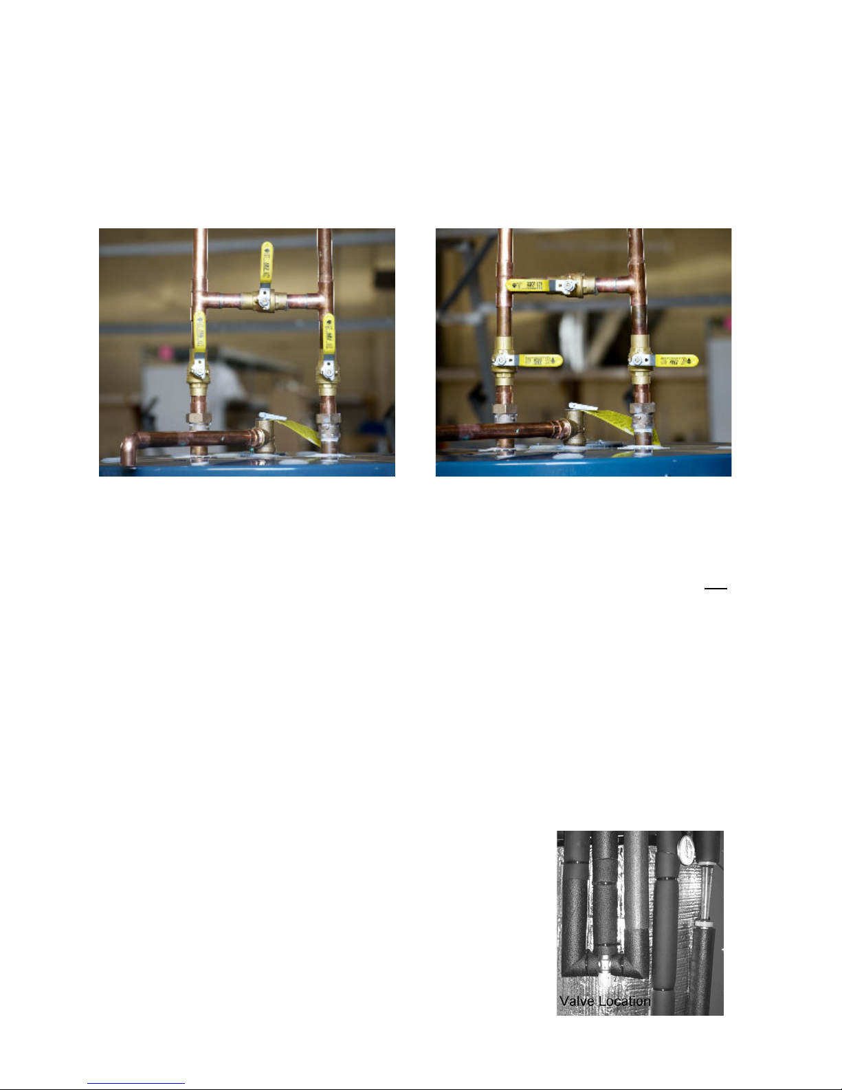
Solar Storage Tank Isolation Valve (Two tank systems only)
The Sol-Reliant solar storage tank can be bypassed** (or “isolated”). In the event that your solar
storage tank ever has a problem or a leak, the solar storage tank can be isolated while
maintaining full hot water service to the house.
Solar Pre-heat Position Bypass Solar Position
When in the solar pre-heat position, the main cold water supply to the entire hot water system
of your house first enters the solar storage tank and flows out of the solar tank to the auxiliary
heater. These two valves are normally open, and the crossover line or bypass valve is normally
closed (see photo left). To bypass solar, change the position of all three valves (see photo right).
The pre-heat line from the solar storage tank to the auxiliary water heater feeds through the left
side (when facing the valve handle) on the same four-port isolation valve.
When in the bypass or isolated solar position, which involves turning the isolation valve
handle ¼turn or 90 degrees, the cold water supply to the entire hot water system of your house
is redirected within the isolation valve itself from the solar storage tank to your auxiliary heater.
In this position water neither enters nor leaves your storage tank; instead it passes into the valve
through the top right port and directly out through the top left port.
**ONLY BYPASS YOUR SOLAR STORAGE TANK IN THE EVENT
OF A LEAK OR FOR SERVICING.
Tempering Valve
To protect from scalding when the solar pre-heat temperature is
higher than 120 degrees, a tempering valve is installed just before
hot water enters the building to automatically allow cold water to
mix with hot so a consistent temperature is passed to all the hot
water faucets. This valve is adjustable from 110 to 160 degrees. It
is possible to have 160-degree solar heated water stored in your
Cold Mixed Hot
\\\

8
tanks, yet the temperature entering the building is never above that of the tempering valve
setting.
Heat Transfer Fluid
The Sol-Reliant system uses a Class II heat exchange fluid produced by DowfrostTM HD, a non-
toxic propylene glycol antifreeze, in combination with distilled water, in the solar loop plumbing
as a heat transfer fluid. The fluid is dyed bright yellow to aid in leak detection. A 50% glycol
solution is adequate to protect from freezing down to -20 degrees F.
DowfrostTM HD - Propylene Glycol Fluid - Freeze protection mixing chart
Freezing % Glycol
Temperature, °F by Volume Freeze tolerance limits are based on an assumed
26 10 set of environmental conditions
19 20
8 30
-7 40 For more information, see MSDS Data Sheets
-28 50
-60 60
<-60 70
Technical data for operating fluid
The service temperature range for DowfrostTM HD is -50 to 325 degrees F. At full strength it has a freezing point of
-100 degrees F. The boiling point is 325 degrees F. Mixed with water, DowfrostTM HD has no flash point. In pure
concentration the flashpoint is 214 degrees F. Specific Heat: In a 50% glycol/water solution, at –20 degrees F the
specific heat is .756; at zero degrees, .764; at 30, .766; at 50, .80; at 70, .812; at 90, .824; at 110, .836; at 130, .845;
at 150, .860; at 170, .872; at 190, .864. In 50% or greater glycol solutions, the vapor pressure below 100 degrees F is
zero. It rises to 1.1 psia-English units at 110 degrees F, 1.5 @ 120; 1.9 @ 130; 2.5 @ 140; 3.2 @ 150; 14.6 @ 200;
and 25.6 @ 250. Viscosity in a 50% solution @ -10 degrees F is 95.97; at zero degrees, 61.32; at 10 degrees, 40.62;
at 30, 19.66; at 50, 10.65; at 70, 6.34; at 90, 4.05; at 110, 2.79; at 130, 2.02; at 150, 1.53; at 170, 1.20; at 190, .97; at
210, .81, and at 230, .69.
Instructions for inspection, treatment and disposal of fluid
An easy and reliable way to read your pH level is to use narrow range pH paper such as
pHydrion Control paper with a 7.2 to 8l8 ph range. It should be between 8 and 10. Any fluid
below the pH of 7 should be replaced.
You can quickly determine the condition of your fluid by examining its appearance and odor.
Any drastic variation from the initial fluid specifications, such as a black or dark-gray color,
presence of an oily layer, burnt odor, or any heavy sludge indicates the need for replacement.
DowfrostTM HD is non-toxic and biodegradable. It may be handled without special equipment.
Small spills may be soaked up with common absorbent material. Clean up with water. More
information can be found on the Dow website (www.dow.com) or by calling 1-800-447-4369.
9
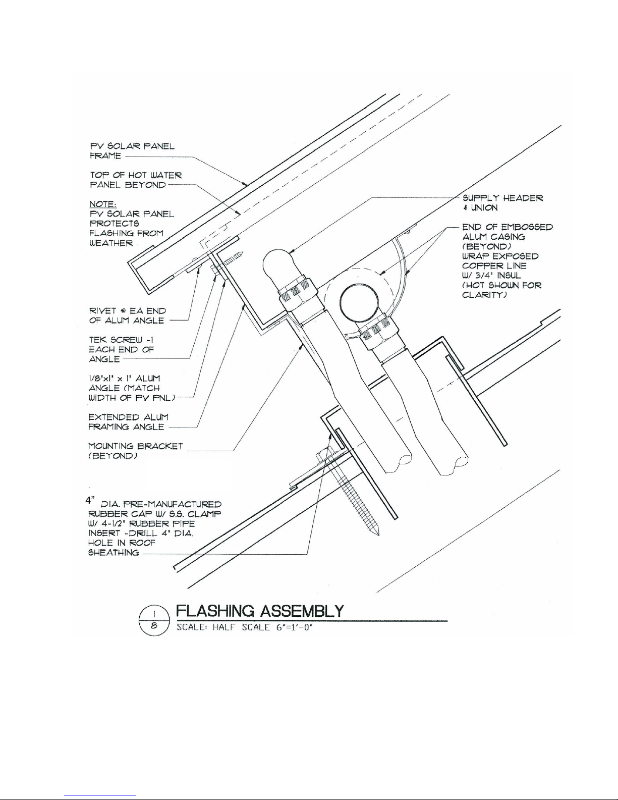
Roof Flashing
The Sol-Reliant uses a single stainless steel flashing for both pipes penetrating the roof. With
the accompanying rubber boot it allows water-tight penetrations in a single, well-protected
location. The Sol-Reliant uses no-caulk flashings for all other flashings, one for each of the
standoff brackets that support the collector and another for the electrical weatherhead.
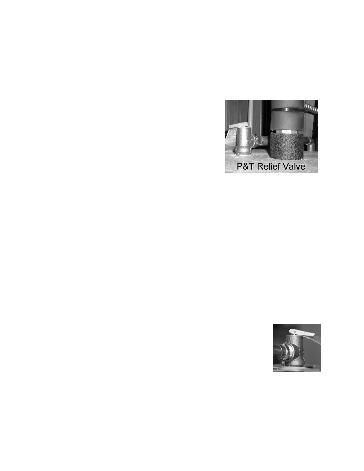
Pressure and Temperature Relief
The Rheem Solar Pre-Heat Storage Tank includes a
temperature and pressure relief valve (P & T valve) located
on top of the tank. This is an emergency over-temperature
and over-pressure valve to protect the tank. If the valve
opens for any reason, water under pressure will discharge for
a several seconds.
Toggle Switch and High Limit Switch
The pump circuit contains two switches: One is a manual “On/Off” switch located on top of the
grey electrical box that is attached to the tank next to the flow meter. The other is a high limit
switch installed against the internal wall of the solar storage tank behind the grey box. In order
to preserve the glycol, this White-Rogers #3 LOI-181 switch will open the circuit to the pump
(which shuts the pump off) when the internal tank temperature of the potable water is at 180
degrees F. In the event the temperature reaches 170 degrees in the top of the solar tank, the
system shuts down in order to preserve the glycol. The switch will close at 140 degrees enabling
the pump to operate again if there’s sun.
NOTE: When the pump shuts off, the fluid in the collector drains back into the reservoir
mounted behind the solar thermal collector. This results in the collector being empty or
“stagnant.” Even though the collector can achieve temperatures over 400 degrees F, it is
harmless for it to be empty. Since the heat transfer fluid drains out of the collector into the
reservoir, it is protected from the excessive temperatures that can cause it to degrade.
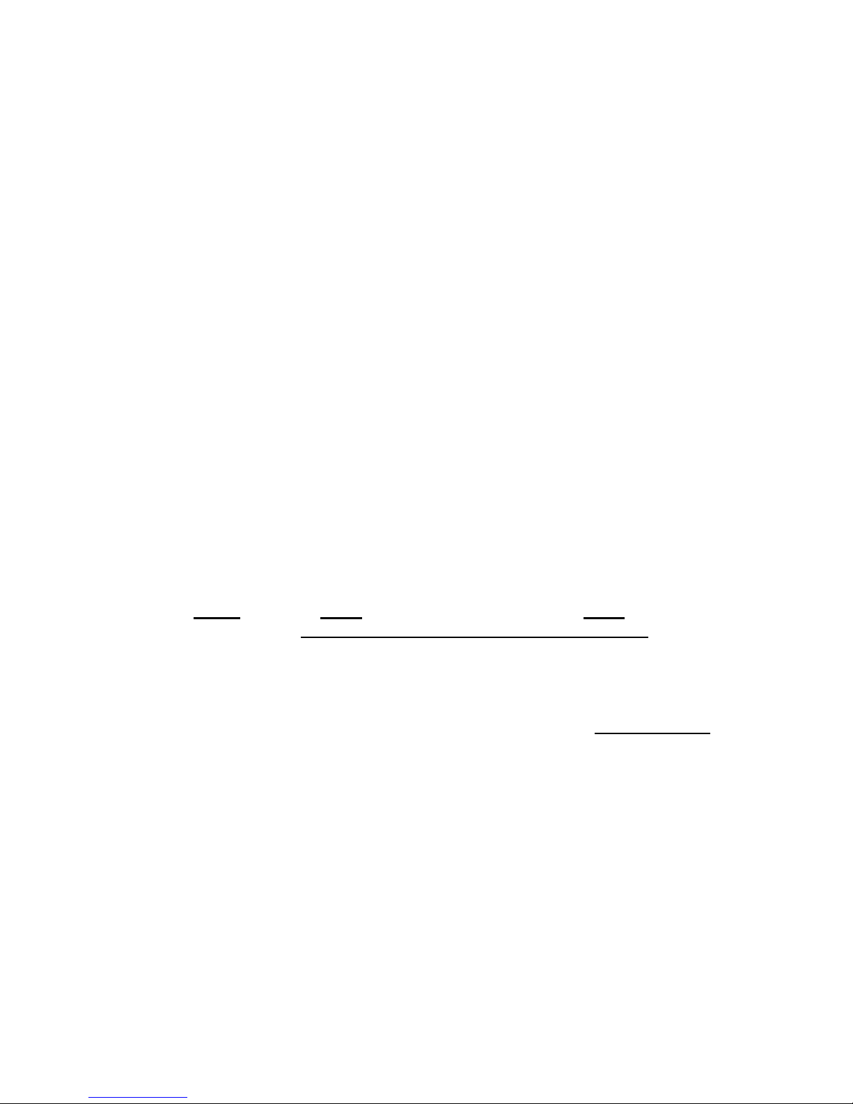
Solar Loop Pressure Relief Valve
A 125 p.s.i. 3/4” Watts 3 L pressure-only relief valve is located just below the
bottom of the photovoltaic module above pipes going through the roof. This
is an emergency relief valve protecting the pump and the solar loop
components from excessive pressure. Since the solar loop is not pressurized,
it is very unlikely this valve would ever be used.
Piping materials
Due to the high temperatures that can occur in a solar water heating system, only copper pipe is
used. Type “M” copper is used on the closed solar loop piping. Any threaded piping or threaded

10
fittings in the system are of brass. Unions are also of brass and have no gaskets. Both solar loop
and potable piping are insulated with minimum R-6 high temperature closed-cell pipe insulation.
Reservoir
The Sol-Reliant system features a uniquely integrated, hidden reservoir. A copper pipe holds
enough heat transfer fluid to keep the pump primed, a custom 2” diameter pipe running the full
length of the collector. When the pump comes on, fluid from the reservoir feeds the suction side
of the pump. As fluid fills the copper tubing in the solar collector, the reservoir level drops. Once
the copper tubing in the collector is filled, fluid returns through the reservoir back to the suction
side of the pump. The reservoir, therefore, never becomes empty, and the pump always has
prime. When the pump shuts off, the fluid drains back into the reservoir, and air rises into the
solar collector. When the system is inactive, the reservoir holds slightly more fluid than the
volume contained in the solar collector. The reservoir is enclosed in a metal shroud, which is
lined with Tekfoil giving the reservoir itself an R-10 insulation.
Pipe Insulation:
3/4” wall closed-cell Armaflex is used to insulate all heat carrying lines as well as the first 5 feet
of the cold water line from the cold water inlet on the solar storage tank. Any exterior insulation
is protected from UV deterioration with PVC jacketing.
Installation Instructions
Pre-installation planning
Tank location: The solar tank is 29” in diameter (not including the pipe tree with pump
assembly and 62” inches tall (not including any piping). If a tank drain pan is needed, you will
need a 32” pan.
Collector Location:
Shading- The top priority is to always locate the collector where it will get the best
exposure to the sun, especially the PV module. Stay away from trees and other shading as
much as possible. Locate the solar collector high on the roof near the peak to minimize
present and future shading. There should be no shading between the hours of 10 a.m. to 4
p.m.
Tilt and Orientation- The optimum tilt and orientation for your location can be obtained
from your state energy office or www.nrel.gov. As a rule, tilt and orientation are critical,
but concessions can be made in most cases to “flush mount” the solar collector to an
existing roof pitch with only nominal losses in efficiency.. Usually, orientation can be 20
degrees east or west of optimum with negligible energy loss. The collector can be
mounted flat if necessary but some degree of tilt is recommended.

11
Types of roofs - Instructions are included in this manual for composition, cedar shingle and
cedar shake roofing. For tile, metal, built up or other, contact Sol-Reliant or your dealer for
supplemental pages dealing with specific mounting instructions for your type of roof
Mounting hardware included with the Sol-Reliant system consists of a minimum of 4 UniRac
7” two piece standoffs placed about 8 feet apart in two rows. Additional brackets are available if
desired or needed (steep pitch, high winds or heavy snow loads). Your local building department
will be helpful in determining to what extent the new roof load from the solar collector needs
support.
Ground Mounting. If installing a ground mounted Sol-Reliant collector, the bottom of collector
must be higher than the top of the heat exchanger (about the middle of the solar storage tank) to
facilitate a full gravity drain of the collector fluid.
Solar Loop Plumbing: The maximum one-way length using 3/4” copper pipe is 100 feet. Using
1” pipe the maximum one-way distance is 150’. All plumbing lines in the solar loop must have
continuous fall (downhill slope of at least 1/8” per horizontal foot) from the bottom of the solar
collector to the top of the heat exchanger. The distance between the solar tank and the collector
should be kept to a minimum.
Potable water. An expansion tank is necessary if a check valve or back-flow prevention device
is present in the incoming water supply. To maximize the operational life of the solar storage
tank the potable water supplied to the system shall have: a) less than 1000 parts per million
(ppm) total dissolved solids, b) less than 500 ppm total hardness, and c) less than 400 ppm total
alkalinity. If necessary, an adequate filter or other water treatment equipment should be installed
upstream of the solar tank to insure water quality at the levels listed.
Wire runs. To ensure less than a 2% voltage drop # 10 wire for runs of 100’ to 150’, # 12 for
runs under 100’. NOTE: NEC Code requires all photovoltaic circuits that enter a building or
structure to have their wiring contained within metallic conduit or raceways between the point of
penetration and the first readily available disconnecting means (the toggle switch located on the
Sol-Reliant storage tank). The PV module must also be grounded against lightning using a #6
bare copper wire, which terminates at a proper earth ground.
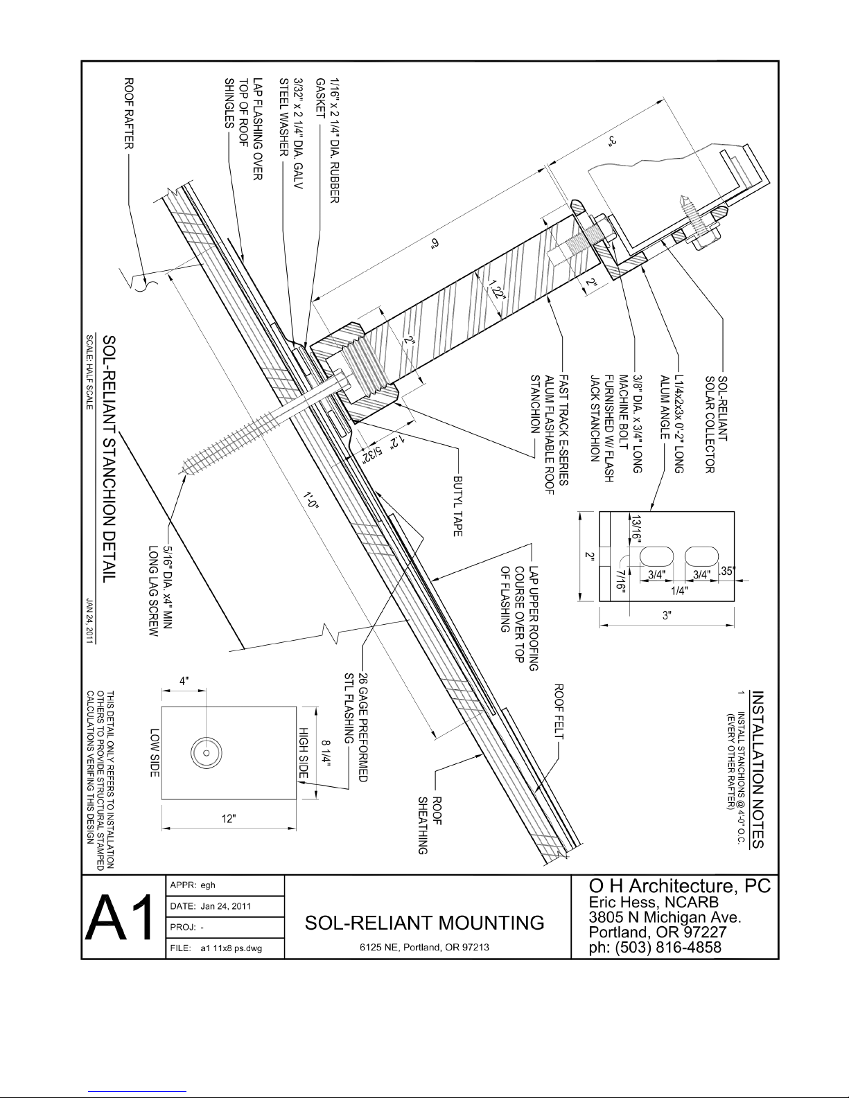
Installing the Collector -Rooftop Installation
STEP 1 (ROOF): Determine where on the roof you want the collector to be placed.
Including the width of the PV module, the collector will occupy a footprint of 15’9” from side
to side by 46-1/2” from top to bottom. NOTE: the Sol-Reliant collector must slope no less than
1’4” and no more than 1/2” from the high side of the collector to the low side where the pipes
come out of the collector. In other words, there should be a very slight slope. In no case should
the collector slope away from the piping. It is recommended that the collector be mounted so
that the top is at least a foot lower than the peak of the roof. Before leaving the roof and
heading for the attic, take a measurement from the peak to where you have determined to place
your top-most brackets. Remember this dimension.

12
STEP 2 (ATTIC): From inside the attic near the peak, locate the rafter or truss, which will be
in the center (side to side) of the collector. Measure 4’ to either side of this member and mark
those rafters. Having determined approximately how far down the roof you want your top-most
bracket, measure precisely from the peak and mark. Start with the rafter that will be further
away from the plumbing penetration. The measurements on the rafter closer to the plumbing
penetration will be made exactly 1 (one) inch lower down the roof. (Since the rafters you are
mounting to are 8’ apart, placing the brackets that will be closer to the plumbing penetration
exactly 1” lower than the other set will automatically give you the optimal 1/8” per foot of
slope throughout the entire collector.) Using a long, small diameter drill bit (1/8” or smaller)
drill a hole up through the roof at the marked location tangent to one face of the proper rafter.
Measure 44-1/2” down from the first hole and drill a second along side of the same rafter.
From the attic, you will have drilled 4 holes, 8’ apart marking the location of all four mounting
brackets that will support the Sol-Reliant collector.
STEP 3 (ROOF): Going back onto the roof, measure over 3/4” from the guide holes and
make vertical mark over the centers of the two rafters designated for mounting. Make a
horizontal mark across the vertical at exactly the same distance down the roof as the hole you
drilled up from the attic. Place the top hole of the power post base over your mark and drill a
pilot hole through both holes in the base. Cut out the composition so that the top edge of the
no-caulk will be under at least two courses of roofing and the center hole will be in the proper
position to accept the standoff post. Then, cut a hole through the lower layers of composition
down to the sheeting, to ensure that the base is mounted flush and solid to the roof. This hole
should be just larger than the power post base. Position the rest of the standoffs in the same
manner, making sure that the set closer to where the pipes will go through the roof is lower so
that the collector slopes the correct direction (i.e.: falling to the right for a right hand collector,
or left for the left hand collector).
STEP 4 (ROOF): Install all four standoff bases using the stainless steel lag bolts provided
(5/16” by 4”). Put the lag bolts through the holes in the bases and bolt them into the pilot holes
you drilled in Step 3. Stick the standoff posts through the gasket hole of the no-caulk flashings,
then slip the no-caulk flashing into the position you cut out in the roofing in Step 3. Screw the
standoff post onto the base. Make sure that it is not cross-threading and that it screws all the
way down. Using the 3/8 bolts provided, attach the four UniRac 2x3” L-feet to the top of the
standoff posts so that the 3” leg is upright and the 2” leg points directly at the other stand off
on the same rafter.
STEP 5 (ROOF): Re-check your measurements. The collector is 46-1/2”. The space, top to
bottom between the inside face of L-foot bracket should be approximately 1/8“ wider than the
SR collector dimension. The L-feet have slotted holes to allow for corrections. Make sure that
these bolts are tight, before moving to Step 6, since the collector will then be covering them.
STEP 6 (ROOF): With the help of at least one assistant, set the Sol-Reliant collector on the
mounting brackets. Measure from the outside edge of the L-bracket to the outside edge of the
collector on each side, slide the collector side to side until centered (centered without regard
for the PV module. Factoring the PV module into the dimensions always makes the collector
13
looking “funny”), that is, the two dimensions between L-foot and collector edge are the same
distance.
STEP 7 (ROOF): Once collector is centered, mark where pipes will go through the roof. Use
a Dixon or other crayon to make this mark (yellow tends to be the most visible). Get your eye
close to the roof and make a vertical line at the midpoint between the two unions. Move to the
side of the collector and repeat the process, this time making a horizontal line. When you’re
done, you will have made a crosshair that precisely marks the center point between the two
unions, both left and right and up and down. Now, slide the solar collector away from the
mark. Using your mark as the center hole, drill a 4” hole in the roof. (NOTE: There should
not be a rafter below, but in the case of irregular or uncommon rafter spacing, you will want to
drill a test hole first to make sure you are clear of all structural members in the attic. Adjust the
final positioning of the solar collector as necessary.)
STEP 8 (ROOF): Install stainless steel flashing centered over the 4” hole. Make sure the top
edge of the flashing is under more than one course of roofing. No caulk should be necessary.
Take the 4” rubber cap-all and place it underneath the unions on the collector. Make sure that it
is no farther up or down the roof than the 4” collar on the flashing. Press the cap-all up against
the unions on the collector. This will leave impressions in the rubber on top of the cap-all.
Using these impressions as marks, drill through the cap-all with a 5/8” hole saw.
STEP 9 (ROOF): Solder the removable union halves from the collector onto the ends of the
two lengths of soft copper tubing provided. Slip these through the 5/8” holes in the cap-all with
the union halves up. Place the cap-all on the 4” collar of the stainless steel flashing, sliding the
soft copper tubing through and into the attic. Make sure the cap-all seats all the way down on
the collar and that the 4” hose clamp is in place (but not tightened) around it. Take note of the
union that is higher and to the inside of the other union. This is the outlet from the “Fat
Tube” drainback reservoir. It is the HOT RETURN PIPE from the collector. You’ll have
to remember which is the supply and which is the return line for the final hook up.
STEP 10 (ROOF): Positioning one installer at each end, slide the collector into place, making
sure that the union halves line up with their respective mates. Make sure the collector is
resting in place in all 4 brackets. Tighten the unions. Use two wrenches, one on each side of
the union. (Your warranty doesn’t cover damage you inflict yourself.)
STEP 11 (ROOF): Double check that the collector has slight downward slope (1/8 inch / ft.)
toward the roof flashing. You are now finished on the roof for the time being. Run one 1”
TEK screw (NO LONGER THAN 1 inch) through the top of both vertical slots of each of the
4 L-feet and into the side of the solar collector. Do not over tighten. Tighten the rubber boot
onto the flashing via the stainless steel clamp on the boot.
14

15

16
The “Anti-Siphoning Assembly” consists of brazed fittings configured so that the reduction in
pipe size is done in the vertical rather than horizontal plain. This prevents any possibility for
thermal siphoning.
17

18
Installing the solar tank & completing the solar loop
Your Sol-Reliant system comes with the lower portion of the solar loop pre-plumbed and
pressure tested. The pump (with both its manual and high-limit switches) is installed on the tank.
The pump is attached to the “supply line” (the pipe in which fluid goes up to the collector). The
Flow meter is installed in the line above the pump. Isolation valves are located on each side of
the pump, and a Drain/Fill Valve is at the low point in the solar loop on the pipe below the pump.
The other pipe attaches to the “return line” from the collector. Fluid travels downward inside this
pipe from the outlet port on the fat tube at the collector.
STEP 1: Set the tank. Place the solar storage tank on the insulation pad provided. It must be
level, and strapped to the wall for earthquake protection. Level the tank with shims, if necessary.
Larger shims, cedar shingle size, work best. Secure the tank with the earthquake straps provided
according to the directions provided.
STEP 2: Plumb the solar loop, using rigid copper pipe (Type M or thicker), remember to
maintain constant downhill fall between the solar collector and the tank. Strap vertical and
horizontal pipes every 6’. Use two hole pipe clamps, plumbers tape, or other strapping that can
be attached outside the pipe insulation. Attach in such a way that the insulation is not
compressed. Check horizontal runs for fall. Piping must be installed in such a way that the
performance of any structural member or fire rated assembly is not compromised. Local
building codes will dictate what is allowable.
STEP 3: Pressure test the solar loop. Temporarily install a brass plug in the threaded female
fitting located on the collector near the pipes. Although this fitting is temporary you should wrap
the threads to minimize the possibility of leaking. Using a Female Hose Bib Thread by Male
NPT Adapter screwed into a Pressure Gauge with a Schraeder (or “Tire Type”) Valve and an air
compressor, fill the system with air from the Drain/Fill Valve at the bottom of the piping below
the pump. These are simple off the shelf gauges available at hardware stores and plumbing
supply stores. Make sure that the hose bib is open. You test the system to at least 60 psi. In the
event of a leak, a soapy water solution will cause bubbling to result at the leaky joint(s). The pre-
assembled system components from Sol-Reliant have been pressure tested, so check your work
before examining fabricated components. Once the system holds pressure, you may move on to
flushing and charging the system.
Potable water plumbing
STEP 1: Turn of the 220VAC breaker that supplies electricity to the water heater element.
Then shut off the cold water supply to existing water heater. Drain the entire tank. Your existing
tank holds 40 to 80 gallons of water. Once the tank is empty and all wiring and plumbing has
been disconnected, remove it.
STEP 2: Lay the insulation pad provided on the footprint where the solar tank will go. Set the
solar tank on the pad. You are now ready to route the cold water supply to the solar tank.

19
The line on the left at the top of the tank is the hot outlet of the solar tank to your back up water
heater. The line on the right is the cold inlet from the cold supply to the hose.
STEP 3: Place a Tee in the line downstream of the shut off valve. From one of the two open
ports of the Tee, plumb to the cold inlet port on the top of the solar tank. It is important to create
a thermal trap in the cold water supply. This is accomplished by plumbing the line straight down
12-18” and then back up. The remaining open port of the cold water tee needs to be plumbed to
the cold side of the tempering valve (marked “Cold”). The tempering valve should be located
12”-18” below the top of the tank.
STEP 4: Complete the plumbing of the tempering valve. From the “Hot” outlet port water
heater, plumb to the “Hot” side of the tempering valve (marked “Hot”). From the “Mixed” port
(in the middle) of the tempering valve, plumb to the hot water service to the house.
STEP 5: If a pressure reducing valve, check valve, or back flow preventer is installed on the
incoming water supply, a properly sized expansion tank must be installed on the potable supply
to the solar system.
STEP 6: You can now turn the water back on from the main hot water shut off. It will take the
solar tank a while to fill. Turn on a hot water valve somewhere in the building to let air escape.
Allow water to run for several minutes after air is purged in order for flux and impurities in the
lines to clear.
Table of contents
Popular Water Heater manuals by other brands


Spheros
Spheros Thermo S 230 Warranty manual

AMP
AMP AMPW 400 Installation, operation and maintenance manual

Heatrae Sadia
Heatrae Sadia UTC 99 Fitting instructions and user guide

Triton
Triton IVORY 5 Installation and operating instructions

DeDietrich
DeDietrich B 150 T Installation and service manual

Timberk
Timberk WHN-4OS instruction manual


