Solar Fabrik Professional 54 User manual

Play it safe
Installation guide solar modules
Professional
Vision

Professional, Vision
2 1408TU0710
Technical modifications and modifications of the product design are reserved. The technical information
at the time of production of the product are valid.
© Solar-Fabrik AG, Freiburg, 2014
DIN EN ISO 9001
Quality management system
DIN EN ISO 14001
Environmental management system
BS OHSAS 18001
Occupational health and safety management system
Status: 07.08.2014 / Document number: 1408TU0710

Professional, Vision 3
Vision 54 | frameless
Professional 60
Vision 60
Professional 54
1408TU0710
Installation guide

Professional, Vision
4
1408TU0710
Safety information
JGeneral safety information
The operation and maintenance of a PV system
require a substantial level of technical knowledge.
Therefore, any work on the system may only be
carried out by qualified and authorized personnel.
Make sure to read these mounting instructions
carefully before installing, commissioning
or servicing the PV system and keep these
instructions in a well accessible location. Failure to
comply with these safety instructions may result in
personal injury and product damage. Please keep
children away!
We strive to be the leader in innovation and
research, while continuing to improve our
products.
For this reason we reserve the right to make
changes to this installation guide without prior
notice.
JImportant safety instructions
The use of these modules must comply with
original design purposes. The modules should not
be altered technically. When mounting, make sure
that the valid local building regulations, standards
and accident prevention regulations are adhered
to. Make sure that all required safety instructions
for the mounting and operation of any further
system components are also adhered to.
JWarning: Extreme Danger
due to electrical shock!
Solar modules generate electricity. When exposed
to light, a voltage occurs, which can be dangerous
and life-threatening. Even though the individual
modules generate a relatively low voltage of
50 V DC, the voltage will accumulate as soon as
several modules are connected in series. Modules
connected in parallel result in accumlation
of the currents. Although the fully insulated
plug contacts are designed to protect against
accidental contact, the following instructions must
be followed when handling the solar modules in
order to avoid combustion, spark formation and,
above all, fatal electrical shocks:
XNever insert electrically conducting pieces into
the plugs and sockets!
XDo not wear metallic jewelry during
mechanical and electrical installation!
XKeep the tools and work area dry! Only install
solar modules and wires with dry plugs and
sockets!
XMaintain utmost caution and care! When
working on the wires, always use both tools
and gloves which are insulated!
XDo not disassemble the modules! Never
remove parts or name plates fitted by the
manufacturer! Only use flawless modules! Do
not treat the back side of the modules with
sharp objects, paints or adhesives!
XDo not expose modules to artificially
concentrated sunlight
It is absolutely necessary that the wiring of the
modules is only carried out by qualified and
authorized personnel!
Professional, Vision
5
1408TU0710
JWarning:
Danger due to high voltage!
Even in disconnected condition the inverter can
retain high voltages, which is a major shock
hazard. Therefore:
XBe very cautious when working with the
inverter and wires!
XAfter switching off the inverter as well as
before working on the inverter, make sure to
regulate the time intervals as recommended
by the manufacturer so that the high voltage
components can be discharged!
Make sure to adhere to the assembly regulations
of the inverter manufacturer!
JWarning:
Danger due to electric arc!
The solar modules generate a direct current when
exposed to light. When opening a closed circuit,
e.g. disconnecting the direct current wire from the
loaded inverter, a fatal electric arc may occur.
XNever disconnect the solar generator from the
inverter while the inverter is connected to the
grid!
XMake sure to use only flawless wire
connections! Connect wires seamlessly and
keep them free from dirt!
JElectrical installation
The solar modules are designed for use in PV
systems of application class A and are approved
for operation in systems with dangerous direct
current (more than 120 V DC in accordance
with EN 61730) and power. PV modules of this
application class are approved for operation in
installations with unrestricted access. Professional
and Vision modules from Solar-Fabrik AG, which
are qualified under EN 61730 and have been
properly installed, meet the requirements of
protection class II.
Safety information
J Transport, temporary storage
and safe unpacking
The modules are sensitive technical components,
which must be handled with utmost care.
Therefore, be particularly careful during transport
and temporary storage and leave the modules in
the package until they are used. Always lift and
carry the module with both hands and never carry
by means of the junction box.
Do not drop the modules or place them down
clumsily on a hard floor and/or on the module
corners. Do not place any objects on the modules.
Do not stack the modules without protection.
Avoid deflection of the modules. Do not walk on
the modules. Do not treat with sharp objects and
keep all electrical contact areas clean and dry.
For docum
entation purposes, the serial number should
be noted. If required, the modules should be
temporarily stored in a dry, ventilated room.
Clean, non-slip gloves must be worn during all
transport and installation work to prevent cut
injuries from the panel edges. Contamination
of the solar glass with fingerprints must also be
avoided, as this may damage the special coating
on the glass.
Please pay special attention to the warnings on
the package as well as on the enclosed unpacking
instructions!

Professional, Vision
6
1408TU0710
Installing the module
JMake sure that the installation is
carried out safely:
Protect yourself and other persons from falling,
do not carry out the installation in heavy winds
and eliminate the risk of falling objects as much
as possible. Secure the work area in order to avoid
the endangerment or injury of persons.
JObserve the allowable maximum
mechanical loading:
Do not exceed the maximum mechanical loading
and make sure to consider location-specific
loads such as wind or snow. Remember that the
module might sag when loaded under certain
circumstances. In order to avoid damaging the
module by pointed or uneven structures, do not
place fasteners or cable ties between the rear of
the module and the cross section.
JEnsure that the modules are
grounded properly:
Under the terms of Solar-Fabrik AG, grounding of
the module frame (if present) and the mounting
rack is not required for fault-free operation.
To reduce the risk of electric shock (e.g. due to
static charge) as far as possible, Solar-Fabrik AG
recommends to ask an experienced installer to
carry out a proper grounding. If an external
lightning protection system has been already
installed, the PV system has to be integrated
in the existing lightning protection concept
by a specialist. Country-specific standards and
regulations must be observed.
The grounding connections between the modules
must be checked and accepted by a qualified
electrician. Furthermore, the main grounding may
only be connected by a qualified electrician.
In the USA and Canada, a grounding method
approved by Underwriters Laboratories (UL) is
obligatory.
To provide proper grounding, an optimal electrical
conductivity is required. For this purpose,
grounding holes are provided at the rear of the
module frame (if present).These grounding holes
are marked by a stamped ground symbol.
Connect the grounding terminal only to the provided and
marked grounding holes at the rear of the module frame.
Grounding symbol:
For grounding we recommend the Solklip
grounding terminal with integrated thread-
cutting screw, (UL 467 approved, UL number
E69905), manufactured by Tyco Electronics.
Observe the additional instructions at www.
tycoelectronics.com. These grounding terminals
accommodate 4 mm² (AWG 12) and 6 mm²
(AWG 10) stripped solid copper wires. The wires
must not be cut, notched or scratched. No further
preparation is required.
Professional, Vision
7
1408TU0710
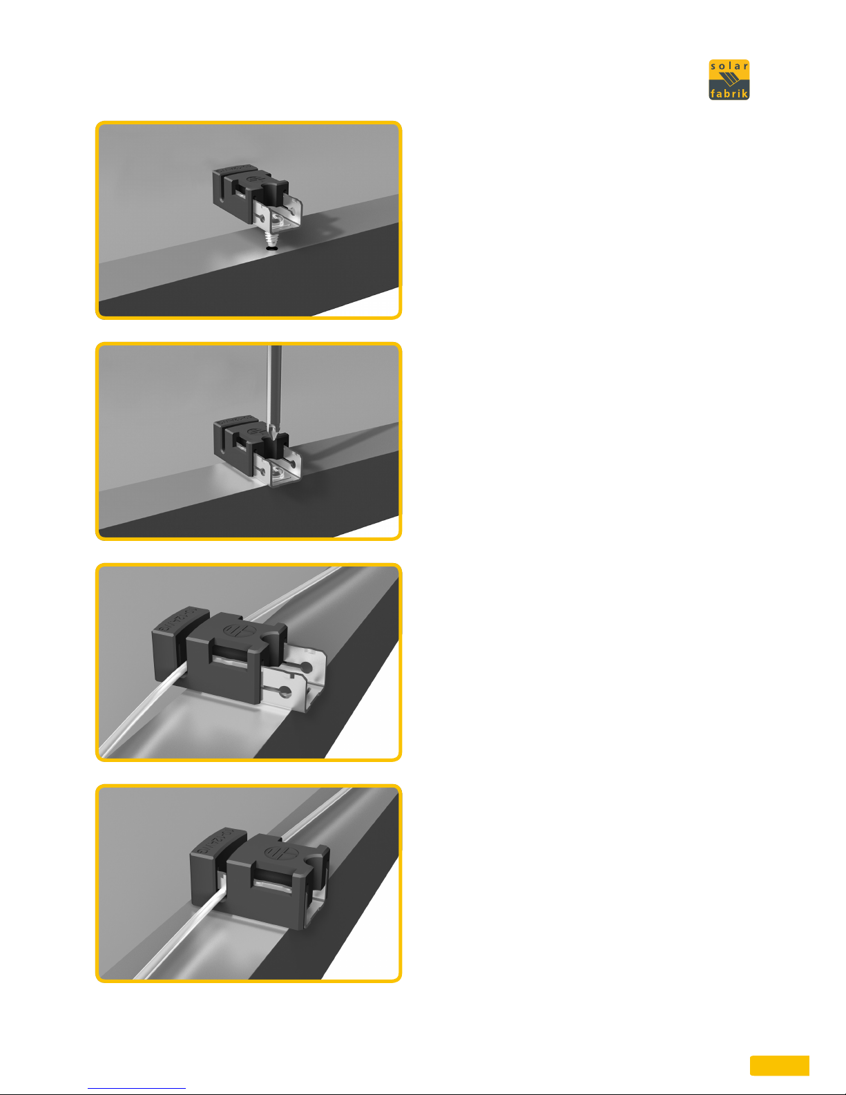
JMounting of grounding terminal
on frame
The grounding terminal must be placed on the
frame in such a way that the screw touches the
grounding hole. Using a screwdriver, install the
screw into the grounding hole until its head is
flush with the base and the base is flush with the
frame.
Then, turn the screw another quarter or half turn.
The thread-cutting screw should be torqued by
20.4 lb in and 24,8 lb in (2.3 and 2.8 Nm).
JWire placement
Insert the cable into the wire slot. Then push in
the wire on both ends into the slot. (The wire slot
will cause the wire to be slightly curved as shown.)
JTermination
The slider must be engaged (slider covers the
base). Using cable clamps, move the slider over
the base until it covers the base. This terminates
the wire. To open the slider a slotted screwdriver
can be used.

Professional, Vision
8
1408TU0710
Installing the module
JEnsure comprehensive fire
protection:
The installation of on-roof systems may influence
the fire safety of a building. Improperly installed
systems can present even more of a danger in
the case of fire. Therefore, the modules of an
on-roof system must always be installed over
a fire-resistant surface. As the module is not
regarded as explosion-proof it must not be
installed near inflammable gases and vapors e.g.
close to gas containers, painting installations or
gasoline stations. Furthermore, the module must
not be installed next to open fire and flammable
materials.
JMake sure that the surroundings
are suitable:
The module is designed for use in temperate
climate. Make sure that after installation
the module is neither subjected to artificially
concentrated sunlight, immersed in water or
continuously splashed with liquids. By all means
make sure that the module is not subjected to
abnormal chemical exposure. Therefore, due
to the expected emissions, installation in the
immediate vicinity of production facilities is not
recommended. Exposing the module to extreme
levels of salt or sulphur may lead to corrosion.
JThe correct installation situation
It is very important that the module fulfills the
technical requirements of the overall system.
Therefore, care must also be taken that the
module is not exposed to any negative mechanical
or electrical influence from other system
components. Only connect modules with the
same rated current in series and modules with
the same rated voltage in parallel. The modules
may only be operated at the allowable system
voltage; operation at a higher voltage is not
recommended.
JThe correct location for installation:
The module must not be installed as overhead
glazing or vertical glazing, e.g. on a facade.
Beside the module itself, the mounting system
must also be suited to the expected conditions
at the location of installation (snow, wind) and
withstand them easily. The bottom side of the
module frame (if present) features holes for
draining precipitation water. Make sure during
installation that these holes retain their function.
For portrait mounting, the junction box may be
mounted facing up or down on the underside
of the module. This applies to the Professional
60 series. Otherwise, the junction box must be
mounted facing upwards on the underside of the
module.
JYield maintenance through optimal
alignment and inclination:
We advise you to familiarize yourself with the
appropriate alignment and inclination of the
modules prior to installation in order to ensure
an optimal system yield. The ideal conditions for
the generation of electricity are accomplished
when the sun rays reach the generator surface
perpendicularly. For modules connected in a
series, make sure that all modules have the same
alignment and inclination in order to avoid
performance losses.

Professional, Vision
9
1408TU0710
JInstall the module in an area
free of shade:
Even a low degree of shading will have a negative
effect on the system yield. Therefore, the system
must be installed in a location without shading.
The module should never be shaded completely
during the whole year and be exposed to direct
sunlight for several hours per day even in less
favorable periods of the year.
JEnsure an appropriate ventilation
on back:
By an appropriate ventilation on the back, an
accumulation of heat with adverse effects on the
performance can be avoided.
JSecure attachment
To ensure that modules are installed correctly,
make sure to securely attach the modules at least
four points. Framed PV modules can be clamped
on both the short and long sides. Frameless Vision
modules must be clamped on the long sides and
cannot be installed with arbitrary clamp types.
Only special laminate clamps from Solar-Fabrik
AG may be used to mount the modules. Use of
unauthorised laminate clamps will render the
product and performance warranty void.
NOTE for Vision series:
The detailed installation instructions in the
separate installation manual must be observed, in
addition to the notes appearing here.
Professional, Vision
10
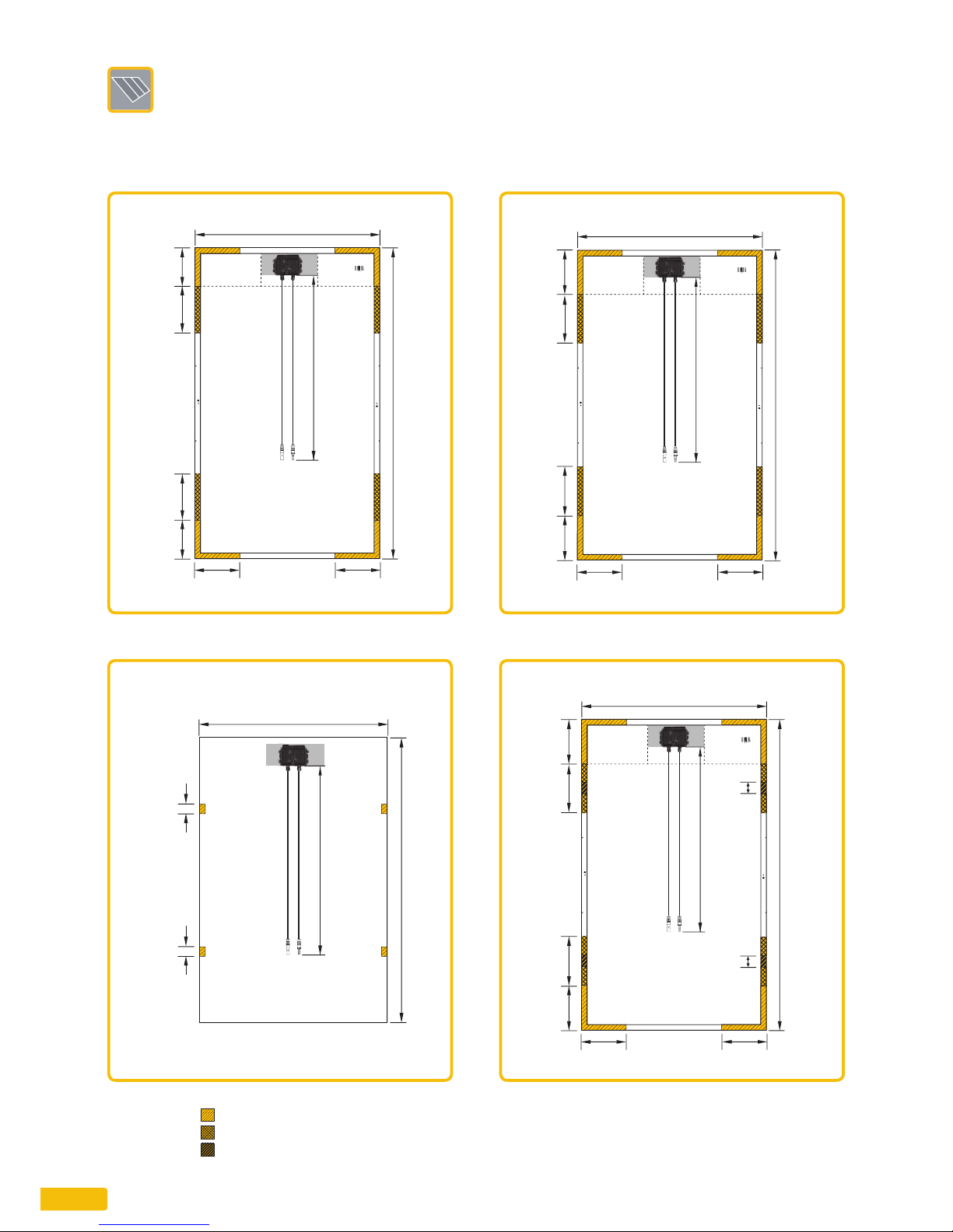
Vision 54 | frameless
L
+
C
3
983
1496
1000
Vision 54
375 ± 20375 ± 20
Professional 60
L
+
C
3
990
1660
240240-500
240 240-500
240 240
1000
Professional 60
Vision 60
L
+
C
3
990
340-400340-400
1677
240240-500
240 240-500
240 240
1000
Vision 60
Professional 54
L
+
C
3
990
1503
210210-460
210 210-460
240 240
1000
Professional 54
1408TU0710
Installing the module
JClamping areas
375 ± 20
(central
clamping
point)
375 ± 20
(central
clamping
point)
Approved up to 2,400 Pa
Approved up to 5,400 Pa
Approved up to 6,600 Pa
Clamping areas:

Professional, Vision 111408TU0710
JNote:
Pay attention to the maximum load-bearing
capacity of the modules, with consideration of
wind and snow load zones, the terrain category
and the height of the building.
JInstallation data:
There are several methods to connect the modules
to substructure: by clamping the modules from
the front (example A) or by bolting the modules
from the back (example B) using the provided
attachment holes.
Use a torque wrench for installation. The required
tightening torque for the above samples is
14.8 lb ft (20 Nm). Use M6 bolts made of V2A.
Only use the provided holes for installation.
If any further holes are drilled, the warranty
will no longer apply. For laminates, use the
explicit installation instructions contained in the
installation manual of the selected mounting
system. Always use appropriate corrosion-proof
fixing materials for installation.
Example A: Clamping wing
Example B: Direct bolting

Professional, Vision
12 1408TU0710
Installing the module
JProper wiring
Never open the connection box! The modules
are already fitted with all necessary wires and
connectors.
JEnsure correct wiring:
The integrated connection cables are UV resistant.
The conductor cross-section of the connection
cables is 4 mm². For wiring, the connection cables
are fitted with prefabricated connectors, which
are protected against reverse polarity.
Keep the total area of all conductor loops as
low as possible in order to reduce the voltages
due to indirect lightning strikes. Always carry
out a careful final check of the wiring prior to
commissioning the generator. If the measured
open circuit voltage diverges from the default
value, a wiring error has occurred. Check for
correct polarity.
Merge the connectors together correctly:
Connectors may only merged together when
dry. Also make sure that a gap-free connection is
possible.
In order not to exceed the max. system voltage at
-10 °C, the 54-cell Professional and Vision modules
must not be connected in series with more than
24 modules. With the Professional and Vision 60
modules, max. 22 modules may be connected
in series. Additionally, the requirements of the
inverters must be observed.
When connecting the modules in parallel, a
corresponding overcurrent protection must be
used. This can be achieved with direct current
fuses, which prohibit return currents greater than
12 A.
Furthermore, the connection requirements and
design regulations of the inverter manufacturer
must be observed.
JOnly use suitable materials:
The system may only be wired using special
solar wires and suitable connectors. It is very
important that all necessary materials are in a
flawless electrical and mechanical condition. Only
use single core wires and chose an appropriate
conductor size in order to minimize the voltage
drop. For further connections of the modules only
appropriate cables with a minimum conductor
cross-section of 4 mm² must be used.
JProtect the wires from adverse
environmental effects:
Only use UV-resistant cable ties for the
attachment of the wires to the mounting system.
Protect the exposed wire from possible damage,
e.g. by routing it in plastic tubes. Avoid direct
exposure to sunlight.
Under usual and expected conditions, a PV
module can generate a higher current and/or
higher voltage as stated with the standardized
test conditions. For this reason, the Isc and Uoc
values specified on the module must be multiplied
by a factor of 1.25 to determine the rated voltage
values of conductors, fuse values and the size
of control systems connected to the PV module
output.
JMake sure connectors are mounted
correctly
To ensure that connectors of the same model are
used, it is permitted to sever the module cable just
before the module connector plug and mount one
of the other connectors approved by Solar-
Fabrik AG.
The KSK4 connector (manufactured by Kostal) is
approved for use by Solar-Fabrik AG.
Additional connectors upon request. Consult your
Solar-Fabrik AG sales representative if you have
any questions.
The connector must be installed according to the
mounting instructions provided for the connector.
Note that all work must take place on the ground
when attaching the module connector.
Always make sure that the module is disconnected
from the generator field while carrying out work.
Make sure that the photoactive side of the
module remains face down while work is carried
out to ensure that voltage is kept at an absolute
minimum.
The full product warranty for the module remains
valid as long as all mounting instructions are
followed and the installation is carried out by a
specialist technician.
It is not permitted to combine incompatible
connectors from different manufacturers.
Combining connectors from different
manufacturers will render the product warranty
void.

Professional, Vision 131408TU0710
JMaintenance and cleaning
Usually, the modules are automatically cleaned
by rain. With an inclination of more than 15° the
modules generally need no additional cleaning. In
the case of severe contamination, we recommend
that the modules are cleaned with ample water
and without cleaning agents.
In the case of severe contamination, we
recommend cleaning with plenty of water with
a low lime content. Please do not use a nozzle
attachment, and ensure that only moderate
water pressure is used. Using cleaning products
and scratching cleaning devices will damage the
special anti-reflective coating and render the
product and performance guarantees void. Under
no circumstances may contaminants be scratched
or rubbed off without moisture. Damage to the
highly efficient anti-reflective surface may change
the visual appearance of the module surface and
result in decreased performance.
Use of automatic cleaning machines for solar
energy systems is at your own risk, and is not
authorised by Solar-Fabrik AG in any way.
Inspect the installation on a regular basis and
check it for
Xsecure fixing and corrosion-free condition of all
mountings
Xsecure connection, cleanliness, integrity and
corrosion-free condition of all wire connections
Xtransition impedances of the potential
equalization
JInformation about liability and
revision level of the instructions
If any of the instructions given in the user
information are not adhered to, Solar-Fabrik
AG will not guarantee the availability and
functionality of the modules. Since the compliance
with the said safety instructions as well as
the conditions and methods for installation,
operation, usage and maintenance of the modules
cannot be checked or monitored by Solar-Fabrik
AG, Solar-Fabrik AG does not accept any liability
for damage due to improper use, incorrect
installation, operation, usage or maintenance.
The text and the figures of this installation guide
comply with the state of technology at the time of
printing.
Subject to alterations.

Professional, Vision
14 1408TU0710
Notes

Professional, Vision 151408TU0710

Play it safe
Solar-Fabrik AG
Munzinger Str. 10
79111 Freiburg
Deutschland
Telefon +49 (0)761 4000-0
Telefax +49 (0)761 4000-199
www.solarfabrik.de
Status: 07.08.2014 / Document number: 1408TU0710
This manual suits for next models
3
Table of contents
Other Solar Fabrik Solar Panel manuals


Popular Solar Panel manuals by other brands

BenQ
BenQ PM245P01 Series installation guide

NEO TOOLS
NEO TOOLS 90-143 user manual

AEROCOMPACT
AEROCOMPACT CompactPITCH XM-P Assembly instructions

Viessmann
Viessmann VITOVOLT 200 5458 installation instructions

Solibro
Solibro SL2 Operation manual

LEJ LINE
LEJ LINE LSK-JC-2V Installation and maintenance manual


