SolarEdge L10US-IB20 User manual

User Guide
Uninterruptable Power Supply
for 208VAC Grid
L10US-IB20, L10US-IB40,
L10US-IB60 L10US-IB00,
L15US-IB40, L15US-IB60,
L15US-IB00, L20US-IB60,
L20US-IB00
Version 1.0 September 2021
Cat. No. 2MUM-

.

ii
L10US-IB20, L10US-IB40, L10US-IB60 L10US-IB00, L15US-IB40,
L15US-IB60 L15US-IB00, L20US-IB60, L20US-IB00 UPS
Important Notice
•Copyright © August 2021 SolarEdge Inc. Doc. Part 2MUM-SG-. All rights reserved.
•No part of this document may be reproduced, stored in a retrieval system, or transmitted,
in any form or by any means, electronic, mechanical, photographic, magnetic, or
otherwise, without the prior written permission of SolarEdge Inc.
•All company and brand products and service names are trademarks or registered
trademarks of their respective holders.
•Patent marking notice: see http://www.solaredge.com/patent
•The general terms and conditions of delivery of SolarEdge shall apply.
•The content of these documents is continually reviewed and amended, where necessary.
However, discrepancies cannot be excluded.
•The images contained in this document are for illustrative purposes only and may vary
depending on product models.

iii
L10US-IB20, L10US-IB40, L10US-IB60 L10US-IB00, L15US-IB40,
L15US-IB60 L15US-IB00, L20US-IB60, L20US-IB00 UPS
Thank you for selecting this uninterruptible power supply (UPS). It provides you with
protection for connected equipment. Please read this manual before installing the L series
models as it provides important information that should be followed during installation and
maintenance of the UPS and batteries, allowing you to correctly set up your system for the
maximum safety and performance. Included is information on customer support and service
if it is required. If you experience a problem with the UPS, please refer to the
Troubleshooting section in this manual to correct the problem. If the problem is not
corrected, please collect information so that the Technical Support personnel can more
effectively assist you.

iv
L10US-IB20, L10US-IB40, L10US-IB60 L10US-IB00, L15US-IB40,
L15US-IB60 L15US-IB00, L20US-IB60, L20US-IB00 UPS
Table of Contents
1. PREFACE ................................................................................................................................................1
1.1. STANDARDS AND CONVENTIONS..............................................................................................................1
1.2. SAFETY SYMBOLS INFORMATION .............................................................................................................. 1
1.3. TECHNICAL SUPPORT ...............................................................................................................................2
2. IMPORTANT SAFETY INSTRUCTIONS (SAVE THESE INSTRUCTIONS) ........................................3
3. MAIN FEATURES ..................................................................................................................................7
3.1. SUMMARY...............................................................................................................................................7
3.2. FUNCTIONS AND FEATURES ......................................................................................................................7
3.3. SYSTEM CONFIGURATION .........................................................................................................................8
3.4. CABINET VIEW ......................................................................................................................................... 9
3.5. DIMENSIONS AND WEIGHT ....................................................................................................................11
3.6. COMPUTER ACCESS................................................................................................................................13
4. OPERATION ........................................................................................................................................16
4.1. OPERATION MODES ...............................................................................................................................16
4.1.1. Normal mode............................................................................................................................ 16
4.1.2. Battery mode (Stored energy mode) ....................................................................................... 16
4.1.3. Maintenance mode (Manual bypass)...................................................................................... 17
4.1.4. Bypass mode ............................................................................................................................. 17
4.1.5. ECO mode.................................................................................................................................. 18
4.2. UPS OPERATION...................................................................................................................................19
4.2.1. Start procedure.......................................................................................................................... 19
4.2.2. Test procedure........................................................................................................................... 19
4.2.3. Maintenance bypass ................................................................................................................. 20
4.2.4. Switch to mechanical bypass................................................................................................... 20
4.2.5. Switch to normal operation (from mechanical bypass) ........................................................ 20
4.2.6. Cold start procedure ................................................................................................................. 21
4.2.7. Shutdown procedure................................................................................................................. 22
4.2.8. Parallel setting .......................................................................................................................... 23
4.3. LCD CONTROL PANEL ............................................................................................................................26
4.3.1. Overview.................................................................................................................................... 26
4.3.2. Introduction............................................................................................................................... 27
4.3.3. Data ........................................................................................................................................... 27
4.3.4. Status ......................................................................................................................................... 28
4.3.4.1. Main ......................................................................................................................................................29
4.3.4.2. Bypass ...................................................................................................................................................30
4.3.4.3. Output...................................................................................................................................................30
4.3.4.4. Battery...................................................................................................................................................31
4.3.4.5. Status info.............................................................................................................................................32
4.3.5. Alarm ......................................................................................................................................... 34

v
L10US-IB20, L10US-IB40, L10US-IB60 L10US-IB00, L15US-IB40,
L15US-IB60 L15US-IB00, L20US-IB60, L20US-IB00 UPS
4.3.5.1. Current alarm .......................................................................................................................................34
4.3.5.2. History...................................................................................................................................................35
4.3.5.3. Buzzer....................................................................................................................................................35
4.3.6. Setting........................................................................................................................................ 36
4.3.6.1. Basic setting .........................................................................................................................................37
4.3.6.2. Language ..............................................................................................................................................38
4.3.6.3. Password...............................................................................................................................................38
4.3.6.4. Brightness and backlight time............................................................................................................39
4.3.6.5. Date and time setting .........................................................................................................................40
4.3.6.6. Communication setting ......................................................................................................................40
4.3.6.7. Bypass settings.....................................................................................................................................41
4.3.7. Advanced settings..................................................................................................................... 43
4.3.7.1. System setting......................................................................................................................................44
4.3.7.2. Parallel setting......................................................................................................................................45
4.3.7.3. Output setting......................................................................................................................................46
4.3.7.4. Battery setting......................................................................................................................................47
4.3.7.5. Dry contact setup ................................................................................................................................49
4.3.8. Maintenance: Touch correction and battery self-test............................................................ 51
4.3.8.1. Battery self-check ................................................................................................................................51
4.3.8.2. Timing daily..........................................................................................................................................52
4.3.8.3. Timing weekly ......................................................................................................................................52
4.3.9. Common .................................................................................................................................... 53
4.3.9.1. INV ON/OFF .........................................................................................................................................53
4.3.9.2. Battery test ...........................................................................................................................................54
4.3.9.3. Fault clear .............................................................................................................................................55
4.3.10. Monitor and LCD software version.......................................................................................... 55
4.4. DISPLAY MESSAGES AND TROUBLESHOOTING...........................................................................................57
4.4.1. Operational status and mode(s)................................................................................................. 57
4.4.2. Faults and alarms reports........................................................................................................... 58
4.5. OPTIONAL FEATURES..............................................................................................................................62
4.5.1. SNMP card................................................................................................................................. 62
4.5.1.1. Functions................................................................................................................................................62
4.5.2. Relay card.................................................................................................................................. 63
5. APPENDIX 1: SPECIFICATIONS ........................................................................................................65
6. APPENDIX 2: TROUBLESHOOTING .................................................................................................70

vi
L10US-IB20, L10US-IB40, L10US-IB60 L10US-IB00, L15US-IB40,
L15US-IB60 L15US-IB00, L20US-IB60, L20US-IB00 UPS
Table of Figures
FIGURE 1FRONT VIEW/SIDE VIEW OF L10US, L15US AND L20US..................................................................................... 9
FIGURE 2REAR VIEW (TERMINAL BLOCK WITHOUT COVER)OF L10US, L15US AND L20US....................................................10
FIGURE 3: DIMENSIONS (INCHES) .................................................................................................................................11
FIGURE 4COMMUNICATION PANEL ..............................................................................................................................13
FIGURE 5MUSER5000 HOMEPAGE ..............................................................................................................................14
FIGURE 6MUSER5000 COMMUNICATION SETTING PAGE ..................................................................................................14
FIGURE 7MUSER5000 APPEND EQUIPMENT PAGE ..........................................................................................................15
FIGURE 8MUSER5000 APPEND EQUIPMENT MANUAL SETTING PAGE..................................................................................15
FIGURE 9NORMAL MODE ........................................................................................................................................... 16
FIGURE 10 BATTERY MODE..........................................................................................................................................17
FIGURE 11 MAINTENANCE MODE (MANUAL BYPASS) ....................................................................................................... 17
FIGURE 12 BYPASS MODE ........................................................................................................................................... 18
FIGURE 13 ECOMODE............................................................................................................................................... 18
FIGURE 14 POSITION OF THE COLD START BUTTON ........................................................................................................... 22
FIGURE 15 MUSER5000 HOMEPAGE ............................................................................................................................23
FIGURE 16 MUSER5000 USER SETTING PAGE .................................................................................................................24
FIGURE 17 MUSER5000 WORK MODE SETTING PAGE.......................................................................................................24
FIGURE 18 MUSER5000 UPS ID SETTING PAGE..............................................................................................................25
FIGURE 19 LCD CONTROL PANEL INTRODUCTION.............................................................................................................26
FIGURE 20 SNMP CARD.............................................................................................................................................63
FIGURE 21 RELAY CONTACTS (DRY CONTACT CARD).......................................................................................................... 63
FIGURE 22 RELAY OVERVIEW .......................................................................................................................................64

vii
L10US-IB20, L10US-IB40, L10US-IB60 L10US-IB00, L15US-IB40,
L15US-IB60 L15US-IB00, L20US-IB60, L20US-IB00 UPS
Table of Tables
TABLE 1BATTERIES QUANTITY .......................................................................................................................................5
TABLE 2CABINET OVERVIEW.......................................................................................................................................10
TABLE 3: DIMENSIONS AND WEIGHTS ...........................................................................................................................12
TABLE 4COMMUNICATION PANEL...............................................................................................................................13
TABLE 5LCD AND LED DISPLAY ...................................................................................................................................26
TABLE 6OPERATIONAL STATUS AND MODE(S).................................................................................................................57
TABLE 7FAULT INFORMATION .....................................................................................................................................58
TABLE 8ALARM INFORMATION ....................................................................................................................................60
TABLE 9RELAY CONTACTS (COMMUNICATION CARD)........................................................................................................64
TABLE 10 SPECIFICATIONS...........................................................................................................................................65
TABLE 11 PROBLEMS AND SOLUTIONS ........................................................................................................................... 70
1
L10US-IB20, L10US-IB40, L10US-IB60 L10US-IB00, L15US-IB40, L15US-IB60 L15US-
IB00, L20US-IB60, L20US-IB00 UPS
1. Preface
1.1. Standards and Conventions
This user manual contains diagrams which include images of the display screen of the UPS.
Unless otherwise indicated, the readings shown in the screen images are only illustrative and
are not intended to match the readings on a specific system in any particular environment.
Operation and control of the L Family UPSes is performed through a touch-sensitive LCD
display screen. In this manual, when explaining how to navigate the control software via the
touch-sensitive screen, the terms "tap", "press", "choose", and "select" may be used
interchangeably to indicate selection of a screen option.
Most of the electrical abbreviations in this document are according to IEEE 280 Standard
Letter Symbols for Quantities Used in Electrical Science and Electrical Engineering.
1.2. Safety Symbols Information
The following safety symbols are used in this document. Familiarize yourself with the
symbols and their meaning before installing or operating the system.
NOTE!
Denotes additional information about the current subject.
CAUTION!
Denotes a caution. It calls attention to a procedure that, if not correctly
performed or adhered to, could result in injury or loss of life. Do not proceed
beyond a caution note until the indicated conditions are fully understood and
met.
WARNING!
Denotes a warning. It calls attention to a procedure that, if not correctly
performed or adhered to, could result in injury or loss of life. Do not proceed
beyond a caution note until the indicated conditions are fully understood and
met.

2
L10US-IB20, L10US-IB40, L10US-IB60 L10US-IB00, L15US-IB40, L15US-IB60 L15US-
IB00, L20US-IB60, L20US-IB00 UPS
WARNING - RISK OF LETHAL ELECTRIC SHOCK!
Denotes an electrical hazard. It calls attention to a procedure that, if not
correctly performed or adhered to, could result in injury or loss of life. Do not
proceed beyond a warning note until the indicated conditions are fully
understood and met.
1.3. Technical Support
You can contact technical support via any of the following methods:
SOLAREDGE Inc. - Critical Power Service Department
•Available via email at Ser[email protected]om
Phone support
US
•Available 24 * 7 * 365 by phone at (510) 498 3333.
Other regions
•Available 24 * 7 * 365 by phone at (972) 73 2403139
3
L10US-IB20, L10US-IB40, L10US-IB60 L10US-IB00, L15US-IB40, L15US-IB60 L15US-
IB00, L20US-IB60, L20US-IB00 UPS
2. Important Safety Instructions (Save These Instructions)
SAVE THESE INSTRUCTIONS!
External DC Circuit Over current Protective Device
CAUTION!
To reduce the risk of fire, connect only to a circuit provided with DC 100
amperes for L10US, 120 amperes for L15US, 160 amperes for L20US maximum
branch circuit over current protection in accordance with the National Electric
Code, ANSI/NFPA 70”.
WARNING! When backfeed protection is needed by local area regulations and codes, please
note that it is not a part of the system design and you must install an external automatic
isolation device on site, in order to prevent dangerous voltage or energy in the input of the
isolation device. The device must be rated according to the system specifications and must
open within 15 seconds after the upstream power supply fails.
HAZARD! If those instructions are not followed it may cause death or serious injury.
A label of this text or equivalent text in your language, must be installed on the UPS, and on
the backfeed isolator protection if it is installed remotely from the UPS.
CAUTION! (UPS having Internal Batteries): Risk of electrical shock –Hazardous
live parts inside this unit are energized from the battery supply even when the
input AC power is disconnected.
CAUTION! (No User serviceable Parts): Risk of electrical shock, do not remove
cover. No user serviceable parts inside. Refer servicing to qualified service
personnel.
CAUTION! (Non-isolated Battery supply): Risk of electric shock, battery circuit is
not isolated from AC input, hazardous voltage may exist between battery
terminals and ground. Test before touching.
WARNING! (Fuses): To reduce the risk of fire, replace only with the same type
and size of fuse.
WARNING! Unit intended for installation in a controlled environment.

4
L10US-IB20, L10US-IB40, L10US-IB60 L10US-IB00, L15US-IB40, L15US-IB60 L15US-
IB00, L20US-IB60, L20US-IB00 UPS
WARNING! Do not dispose of batteries to a fire, the battery may explode.
CAUTION! Do not open or damage the battery, released electrolyte is harmful
to the skin and eyes.
CAUTION! A battery can present a risk of electric shock and high short circuit
current. The following precaution should be observed when working on
batteries: remove watches, rings, or other metal objects, use tools with
insulated handles.
To reduce the risk of electric shock, disconnect the UPS from the main supply
before installing a computer interface signal cable. Reconnect the power cord
only after signaling interconnections have been made.
Servicing of batteries should be performed or supervised by personnel with
knowledge of batteries and the required precautions. Keep unauthorized
personnel away from batteries.
For Replacement of batteries located in a service access area:
1. Servicing of batteries should be performed or supervised by personnel
knowledgeable about batteries and the required precautions.
2. Risk of explosion if battery is replaced by an incorrect type. When
replacing batteries, replace with the same type and number of batteries or
battery packs.
3. CAUTION: Do not dispose of batteries in a fire. The batteries may
explode. Dispose of used batteries according to the instructions.
4. CAUTION: Do not open or mutilate batteries. Released electrolyte is
harmful to the skin and eyes. It may be toxic.
5. CAUTION: A battery can present a risk of electrical shock and high short
circuit current. The following precautions should be observed when working on
batteries:
•Remove watches, rings, or other metal objects.
•Use tools with insulated handles.
•Wear rubber gloves and boots.
•Do not lay tools or metal parts on top of batteries.

5
L10US-IB20, L10US-IB40, L10US-IB60 L10US-IB00, L15US-IB40, L15US-IB60 L15US-
IB00, L20US-IB60, L20US-IB00 UPS
•Disconnect charging source prior to connecting or disconnecting
battery terminals.
•Determine if battery is inadvertently grounded. If inadvertently
grounded, remove source from ground. Contact with any part of a grounded
battery can result in electrical shock. The likelihood of such shock can be
reduced if such grounds are removed during installation and maintenance.
These UPS units are extremely heavy. Caution should be taken in moving and
positioning equipment. The instructions contained within this safety manual are
deemed important and should be closely always followed during installation
and follow-up maintenance of the UPS and batteries.
CAUTION!
The unit has a dangerous amount of voltage. If the UPS indicator is on, the
unit’s outlets may have a dangerous amount of voltage even when not plugged
into the wall outlet because the battery may continue to supply power.
Care should be taken to undertake installation indoors, free from electrically
conductive particles which are under temperature and humidity control, to
reduce the risk of electric shock.
It is best to disconnect the device using the power supply cord. Ensure that the
equipment is placed in a position near the outlet where easily accessible.
Except for replacing the batteries, all servicing on this equipment must be
carried out by qualified service personnel.
Before conducting any maintenance, repair, or shipment, first ensure that
everything is turned off completely and disconnected.
For additional safety instructions, see the Safety section of the Service Manual.
Table 1 Batteries Quantity
Model
Rating
SolarEdge P/N
Description
L10US
10 kVa
L10US-IB20
UPS 10kVA, UL standard, pf 1.0, 3-level
inverter, ±120V, Build-in 20x9Ah
L10US
10 kVa
L10US-IB40
UPS 10kVA, UL standard, pf 1.0, 3-level
inverter, ±120V, Build-in 40x9Ah

6
L10US-IB20, L10US-IB40, L10US-IB60 L10US-IB00, L15US-IB40, L15US-IB60 L15US-
IB00, L20US-IB60, L20US-IB00 UPS
L10US
10 kVa
L10US-IB60
UPS 10kVA, UL standard, pf 1.0, 3-level
inverter, ±120V, Build-in 60x9Ah
L10US
10 kVa
L10US-IB00
UPS 10kVA, UL standard, pf 1.0, 3-level
inverter, ±120V, Long run for external
batteries
L15US
15 kVa
L15US-IB40
UPS 15kVA, UL standard, pf 1.0, 3-level
inverter, ±120V, Build-in 40x9Ah
L15US
15 kVa
L15US-IB60
UPS 15kVA, UL standard, pf 1.0, 3-level
inverter, ±120V, Build-in 60x9Ah
L15US
15 kVa
L15US-IB00
UPS 15kVA, UL standard, pf 1.0, 3-level
inverter, ±120V, Long run for external
batteries
L20US
20 kVa
L20US-IB60
UPS 20kVA, UL standard, pf 1.0, 3-level
inverter, ±120V, Build-in 60x9Ah
L20US
20 kVa
L20US-IB00
UPS 20kVA, UL standard, pf 1.0, 3-level
inverter, ±120V, Long run for external
batteries

7
L10US-IB20, L10US-IB40, L10US-IB60 L10US-IB00, L15US-IB40, L15US-IB60 L15US-
IB00, L20US-IB60, L20US-IB00 UPS
3. Main features
3.1. Summary
This series UPS is a kind of 3-phase input/ 3-phase output-out high frequency online UPS.
The UPS can solve most of the power supply problems, such as blackout, over-voltage,
under-voltage, voltage sudden drop, oscillating of decreasing extent, high voltage pulse,
voltage fluctuation, surge, inrush current, harmonic distortion (THD), noise interference,
frequency fluctuation, etc.
This UPS can be applied to different applications from computer device, automatic
equipment, communication system to industry equipment.
3.2. Functions and Features
3 Phase In/3 Phase Out UPS
It is 3 Phase In/3 Phase Out high-density UPS system, of which input current is kept in
balance. No unbalance problem might occur.
Digital Control
This series UPS is controlled by Digital Signal Processor (DSP); hence it increases reliability,
performance, self-protection, self-diagnostics and many more.
Battery is Configurable
The battery voltage of this series UPS is configured to 20 blocks.
Charging Current is configurable
Through the user interface, the user may set the capacity of the batteries as well as
reasonable charging current as well as maximum charging current. Constant voltage mode,
constant current mode or floating mode can be switched automatically and smoothly.
Intelligent Charging Method
The series UPS adopts advanced three-stage charging method—
•1st stage: high current constant current charging to guarantee to charge back to 90%.
•2nd-stage: Constant Voltage in order to vitalize battery and make sure batteries are fully
charged.
•3rd stage: floating mode.
This 3-stage charging method will extend life of the batteries and guarantee fast charging.

8
L10US-IB20, L10US-IB40, L10US-IB60 L10US-IB00, L15US-IB40, L15US-IB60 L15US-
IB00, L20US-IB60, L20US-IB00 UPS
LCD display
With LCD plus LED displays, the user may easily understand the t UPS status and its
operational parameters, such as input/output voltage, frequency & load %, battery % and
ambient temperature, etc.
Intelligent monitoring function
Using the optional SNMP Card (optional for extra charge), you may remotely control and
monitor the UPS.
REPO function
REPO function (Remote EPO) is available in this series UPS.
3.3. System configuration
UPS device, external or internal batteries make up the system. Depending on the site and
load requirements of the installation, certain additional options are available for the solution.
Planning a UPS system, the following should be taken into consideration:
•The total demand of the protected system shall dictate the output power rating (VA).
Allow a margin for future expansion or calculation inaccuracies from measured power
requirements.
•Backup time required will indicate the battery size needed. If the load is less than the UPS
nominal power rating, then actual backup time is longer.
•The following options are available with extra charge:
•SNMP/WEB card
•Relay card
•Parallel connection

9
L10US-IB20, L10US-IB40, L10US-IB60 L10US-IB00, L15US-IB40, L15US-IB60 L15US-
IB00, L20US-IB60, L20US-IB00 UPS
3.4. Cabinet view
Figure 1 Front view/ Side view of L10US, L15US and L20US
10
L10US-IB20, L10US-IB40, L10US-IB60 L10US-IB00, L15US-IB40, L15US-IB60 L15US-
IB00, L20US-IB60, L20US-IB00 UPS
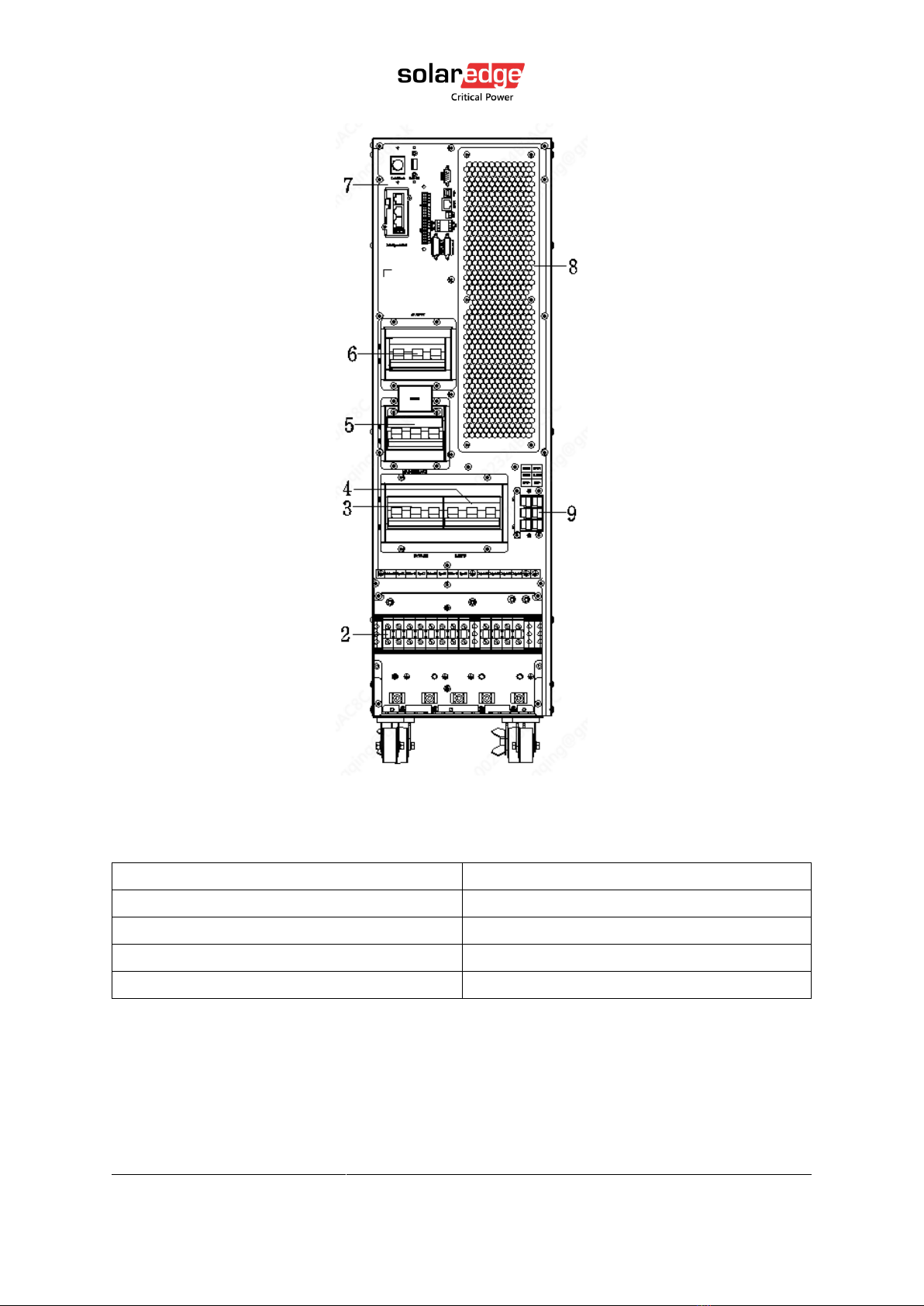
Figure 2 Rear View (terminal block without cover) of L10US, L15US and L20US
Table 2 Cabinet overview
(1) LCD panel
(2) Terminal block for Input, output & GND
(3) Bypass Switch
(4) Mains Switch
(5) Maintenance switch & its cover
(6) Output switch
(7) Communication panel
(8) Rear cover
(9) Terminal block for battery
11
L10US-IB20, L10US-IB40, L10US-IB60 L10US-IB00, L15US-IB40, L15US-IB60 L15US-
IB00, L20US-IB60, L20US-IB00 UPS
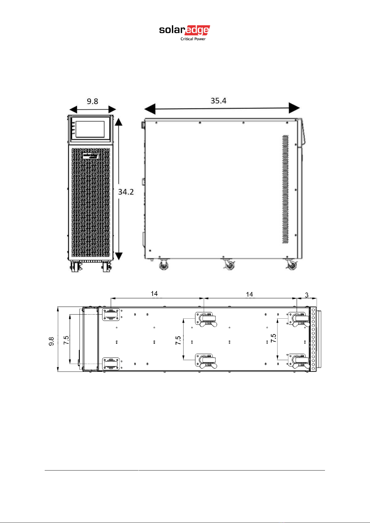
3.5. Dimensions and Weight
Figure 3: Dimensions (inches)

12
L10US-IB20, L10US-IB40, L10US-IB60 L10US-IB00, L15US-IB40, L15US-IB60 L15US-
IB00, L20US-IB60, L20US-IB00 UPS
Table 3: Dimensions and Weights
Model
Width
Depth
Height
Net weigh
L10US-IB20
250mm (9.8’’)
900mm (35.4’’)
868mm (34.1’’)
151kg (332.9lb)
L10US-IB40
250mm (9.8’’)
900mm (35.4’’)
868mm (34.1’’)
204kg (449.7lb)
L10US-IB60
250mm (9.8’’)
900mm (35.4’’)
868mm (34.1’’)
258kg (568.8lb)
L10US-IB00
250mm (9.8’’)
900mm (35.4’’)
868mm (34.1’’)
98kg (216.1lb)
L15US-IB40
250mm (9.8’’)
900mm (35.4’’)
868mm (34.1’’)
204kg (449.7lb)
L15US-IB60
250mm (9.8’’)
900mm (35.4’’)
868mm (34.1’’)
258kg (568.8lb)
L15US-IB00
250mm (9.8’’)
900mm (35.4’’)
868mm (34.1’’)
98kg (216.1lb)
L20US-IB60
250mm (9.8’’)
900mm (35.4’’)
868mm (34.1’’)
259kg (571.0lb)
L20US-IB00
250mm (9.8’’)
900mm (35.4’’)
868mm (34.1’’)
99kg (218.3lb)
Other manuals for L10US-IB20
1
This manual suits for next models
8
Table of contents
Other SolarEdge Power Supply manuals


Popular Power Supply manuals by other brands

Unipower
Unipower Aspiro 1UMS22 instruction manual

Ultra Products
Ultra Products 350 Watt ATX Power Supply user manual

Juniper
Juniper 5000 SERIES user guide

NewMar
NewMar PM-24-80 Installation and operation manual

Elektro-Automatik
Elektro-Automatik EA-PUL 10000 6U manual

Beckhoff
Beckhoff EP1918-0002 operating instructions


Atten
Atten APS3005S-3D user manual

ZALMAN
ZALMAN WattBit II user manual

Sorensen
Sorensen 10-120b instruction manual

Monacor
Monacor PSS-1000USB operating instructions

CARLO GAVAZZI
CARLO GAVAZZI INPUT-OUTPUT POWER SUPPLY MODULES - CONFIGURATION... instruction manual

Xantrex
Xantrex XPower Powerpack 300 owner's guide