P.O. Box 1306, Newport Beach, California 92663 • Phone: 714-751-0488 • Fax: 714-957-1621 • E-Mail: techservice@newmarpower.com
www.newmartelecom.com
P
.O. Box 1306, Newport Beach, Califor
nia 92663 • Phone: 714-751-0488 • Fax: 714-957-1621 • E-Mail:
[email protected]www.newmartelecom.com
3
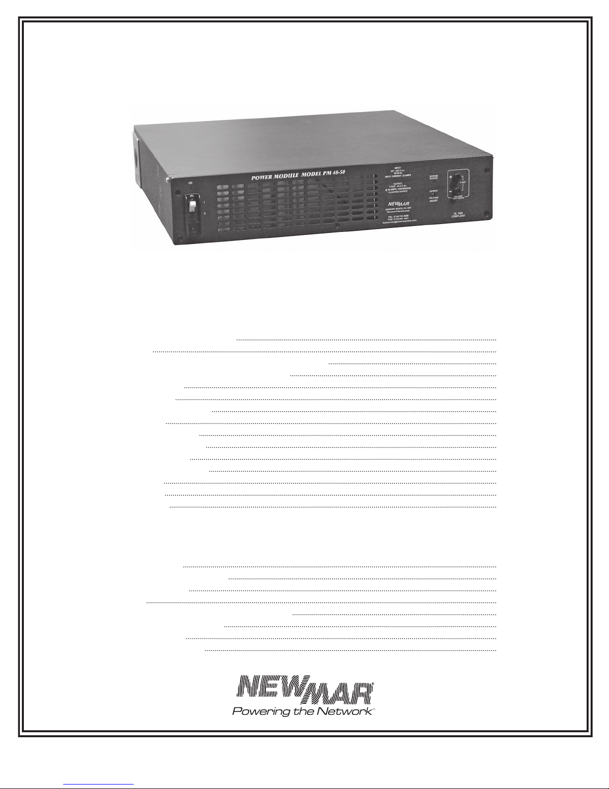
I) OVERVIEW
The PM 2500 Series Power Module is a uniquely adaptable
communication equipment power source which functions as
either power supply or battery charger for 24 or 48 volt d.c.
systems positive, negative or floating ground. Power Modules
may be employed singly or in combination, enabling the
installer to scale the system output from 2500 to 10,000 watts per
rack. Units may be paralleled for N + 1 redundancy and alarm
contacts allow local or remote monitoring. An optional d.c. wiring
quick connect kit Model CCK-4 allows easy replacement of
modules while the system as a whole remains up and running.
Power Modules may be used separately as a power source,
or they may be integrated with NEWMAR’s Power Function
Manager (model PFM-400; rated to 400 amps maximum) to
greatly expand the system capability with other functions such
as digital output voltage/amperage monitoring, multiple load
distribution and low voltage disconnect. (Contact the factory for
complete information regarding the PFM-400.) Note: If the Power
Module is being installed as part of an integrated system with the
PFM-400 refer to the manual which comes with that unit for all
d.c. wiring instructions and functional descriptions.
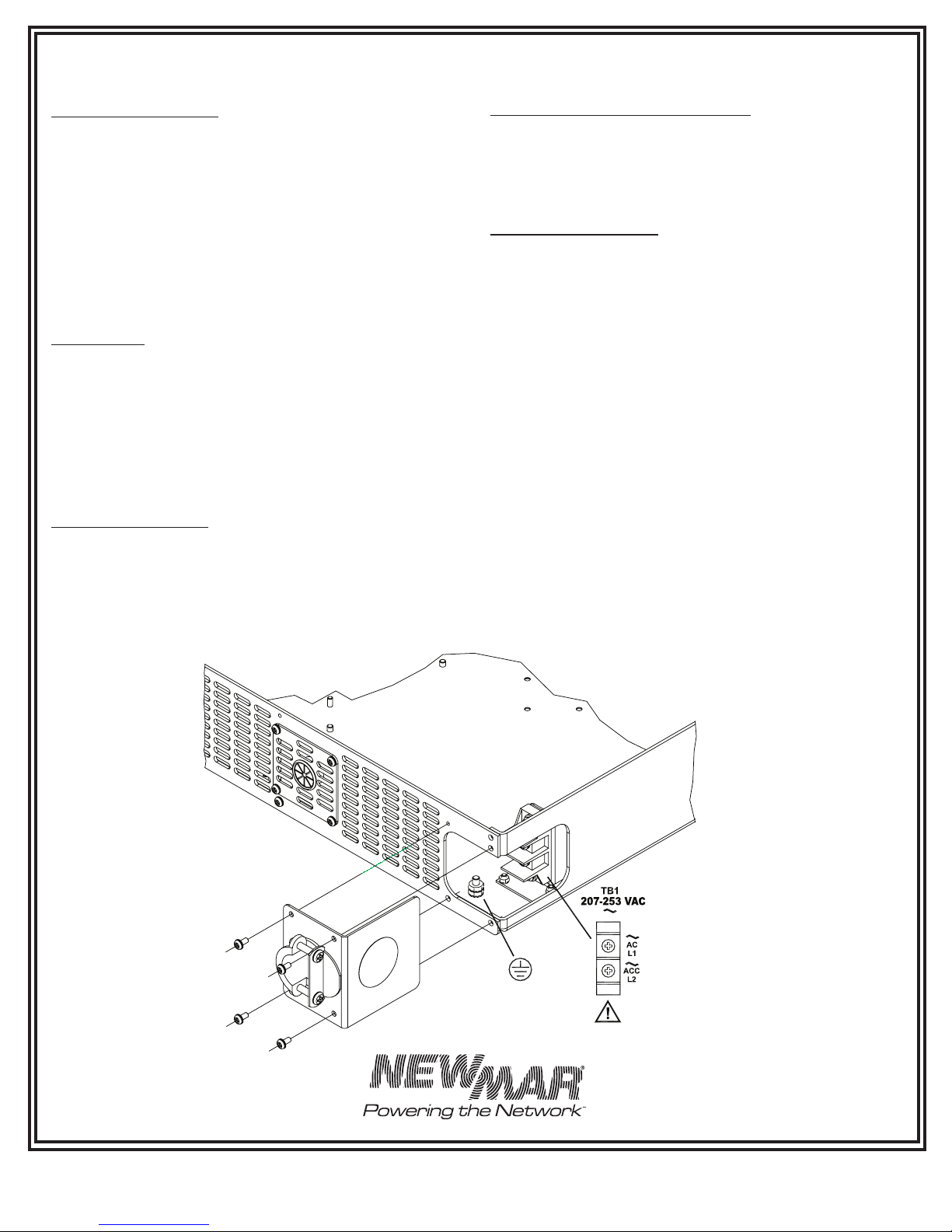
II) AC POWER QUALITY AND
EMI COMPATIBILITY
A) AC Power Quality
Reliability is of prime concern when designing an AC-DC power
system for communication sites. Poor AC input power quality
can seriously impede system reliability. In particular, transient
disturbances on the power lines can severely weaken or cause
failure of semi-conductors in power supplies and communication
gear. It is important that you know the input power quality when
installing the PM. Following is some basic information on
the subject:
Causes
Transients are characterized as a voltage pulse of high energy
and very short duration impressed upon the AC wave form.
These over voltage pulses can range from 1 to 100 times the
normal AC voltage level and can last for a fraction of a cycle to
a few cycles.
Transient disturbances can be placed into two categories:
• Lightning generated
• Equipment generated
A direct lightning hit on a utility power line will cause a high
energy voltage transient to travel in both directions along the
power line. This disturbance can affect equipment hundreds of
miles from the strike point.
Equipment generated transient sources include utility fault
conditions and load switching as well as on-site equipment
such as pumps and air conditioning loads, motors, phase
control equipment.
Recommendations
All PM models are designed to meet IEEE 587/ANSI C62.41
requirements for transient withstand capability. The AC power
source should conform to this specification to ensure reliable power
supply operation.
If the power source quality is suspect or unknown, it is
recommended that an AC power quality survey be conducted by
a power quality consultant or power conditioning firm. Corrective
measures may include lightning suppressors, line conditioners
and filters.
An optional a.c. transient suppressor (see OPTIONS section) is
recommended for installations in third world countries and sites
that are subject to nearby lightning strikes or transients caused by
nearby motor contactors, air conditioning compressors, etc.
B) EMI (Electro-Magnetic Interference) Considerations
The PM Series Power Modules employ switch-mode technology
to convert AC to DC. They are designed to produce minimal
EMI levels when operating (EN6100-3-2 and EN55014-1 Level
A emissions). Although the level of EMI produced may be
acceptable for most radio applications, some installations may not
even tolerate what little EMI is produced.
Analog microwave and other extremely sensitive radio sites may
require additional input/output filtering and careful installation. In
some cases linear power supplies (also available from NEWMAR)
should be considered, as they emit lower EMI (although they are
more susceptible to “brown-outs” or voltage sags and high input
voltage).
C) Other Factors
Some of the various factors which must be considered when
discussing electrical interference include the following:
• RF Signal strength
• Ground loops
• Power and signal cable routing proximity
• Power supply and radio mounting locations
• Antenna, signal, and power grounds