Sorensen 10-120b User manual


This manual suits for next models
7
Table of contents
Other Sorensen Power Supply manuals

Sorensen
Sorensen DCS8-125E User manual
Sorensen
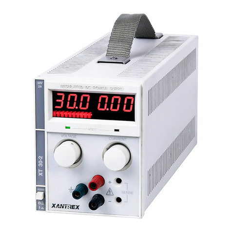
Sorensen XT Series User manual
Sorensen
Sorensen XBT32-3FTP User manual
Sorensen
Sorensen DLM5-350E User manual
Sorensen
Sorensen STM Series User manual
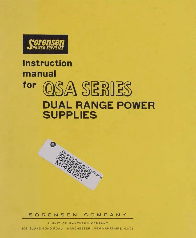
Sorensen
Sorensen QSA Series User manual
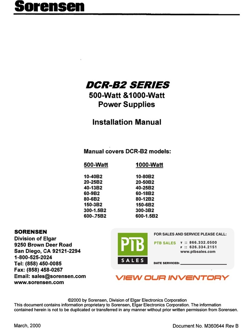
Sorensen
Sorensen DCR-B2 series User manual
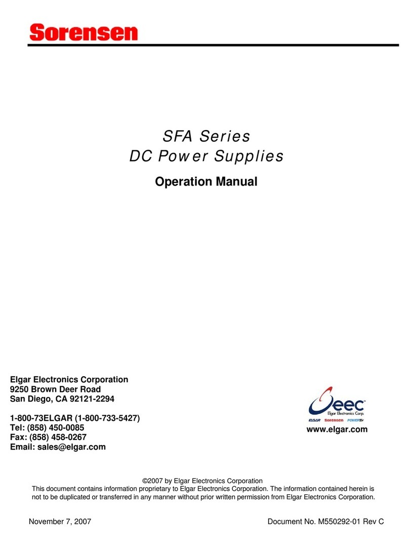
Sorensen
Sorensen SFA Series User manual
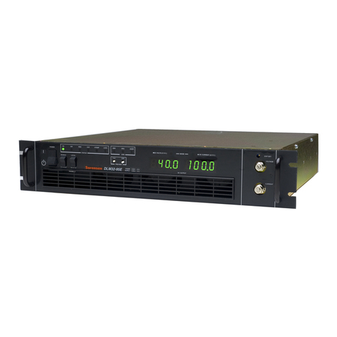
Sorensen
Sorensen DLM-E Series User manual
Sorensen
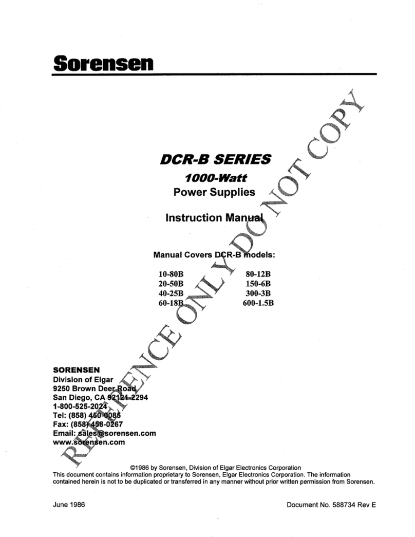
Sorensen DCR 10-80B User manual
Sorensen
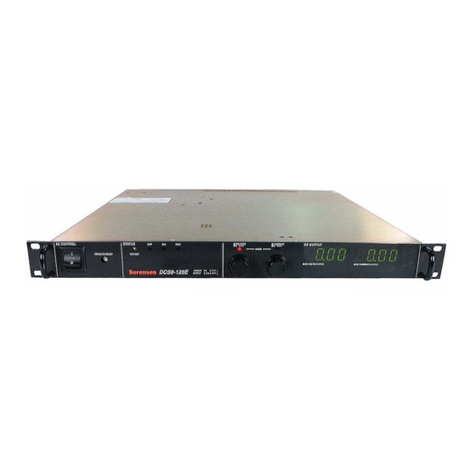
Sorensen 8-125E User manual

Sorensen
Sorensen XEL 120 User manual
Sorensen
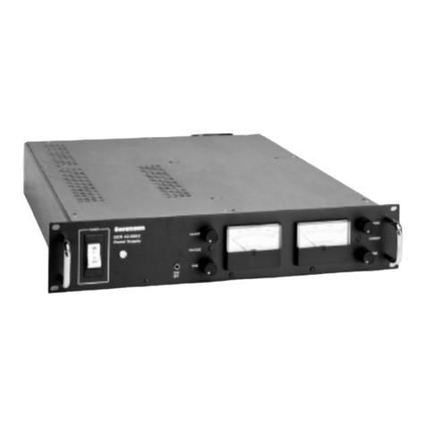
Sorensen DCR10-40B2 User manual

Sorensen
Sorensen DLM 5-75 User manual

Sorensen
Sorensen SL-60-30-150 Use and care manual
Sorensen
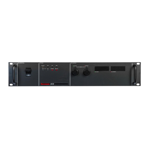
Sorensen DCS8-350 User manual
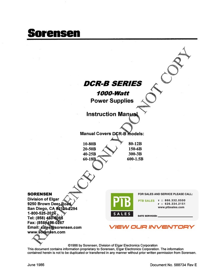
Sorensen
Sorensen DCR-B 10-80B User manual

Sorensen
Sorensen DCR10-40B User manual
Popular Power Supply manuals by other brands
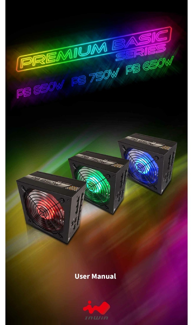
InWin
InWin Premium Basic Series user manual

Fire-Lite
Fire-Lite FCPS-24FS8 manual

Smart power
Smart power DSS1500RT-TBF BATTERY REPLACEMENT INSTRUCTIONS
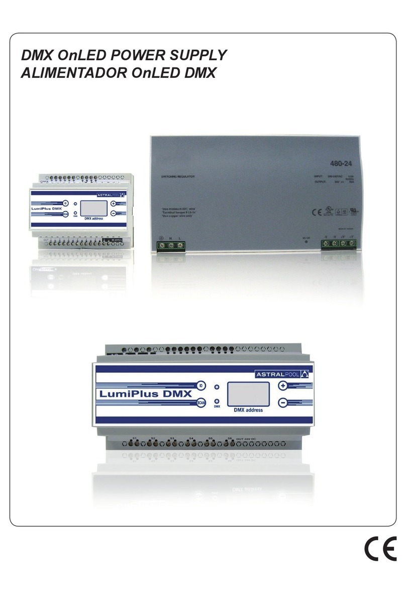
Astral Pool
Astral Pool LumiPlus DMX I0832DMXI52 instruction manual
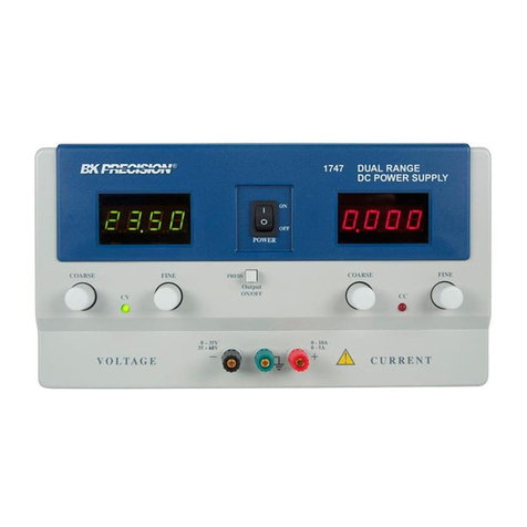
B+K precision
B+K precision 1747 instruction manual
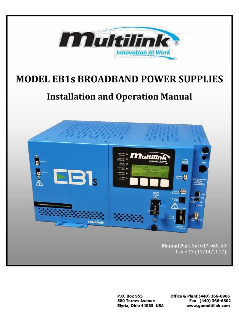
Multilink
Multilink EB1s Installation and operation manual

Delta
Delta IMA-1000 Series Application note
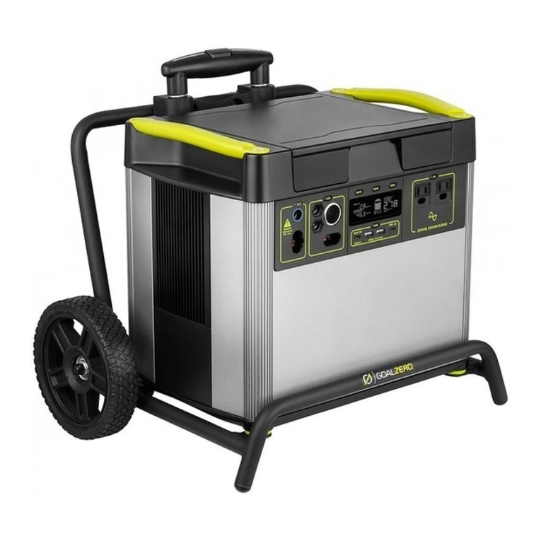
GOAL ZERO
GOAL ZERO Yeti 3000X user manual
Timeguard
Timeguard PSUDALI Installation & operating instructions
Powerten
Powerten 3300I Series Programming manual
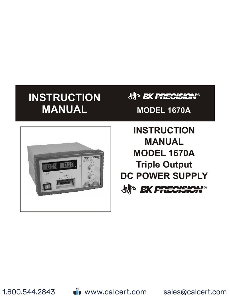
B+K precision
B+K precision 1670A instruction manual
Infinite Play
Infinite Play Z6001 Installation and operation manual
