Alpha Outback Energy APX2PLUS-615G User manual

Page 1of 8
APX2PLUS-615G
Non-Standby Cable TV Power Supply
USER MANUAL

Page 2of 8
IMPORTANT SAFETY AND INSTALLATION WARNINGS
WARNING:
DO NOT ATTEMPT TO SERVICE THIS PRODUCT YOURSELF AS OPENING OR
REMOVING COVERS MAY EXPOSE YOU TO DANGEROUS VOLTAGES OR OTHER
HAZARDS. REFER ALL SERVICING TO QUALIFIED SERVICE PERSONNEL.
SAFETY PRECAUTIONS:
Read this technical manual carefully and completely before proceeding.
Installation and operation of the unit must be performed only by skilled
personnel and always in accordance with applicable electrical codes.
It is recommended that the user contacts local utilities to ensure that the
installation does not interfere with existing utility cables.
Do NOT connect the AC input while servicing the unit or installing the unit.
The unit must be well grounded before proceeding with installation or
operation. Failure to do so can cause electrical shock.
The unit should be installed vertically, and the installation location chosen
such that the unit is adequately ventilated.
Verify that the AC input voltage matches the nominal voltage and frequency of
the unit prior to installation.
Verify that output voltage from the equipment matches the voltage
requirements of the connected equipment (load).
When replacement parts are required, be sure the service technician has used
replacement parts specified by the manufacturer or those that have the same
characteristics as the original part. Unauthorized substitutions may result in
fire, electrical shock or other hazards.

Page 3of 8
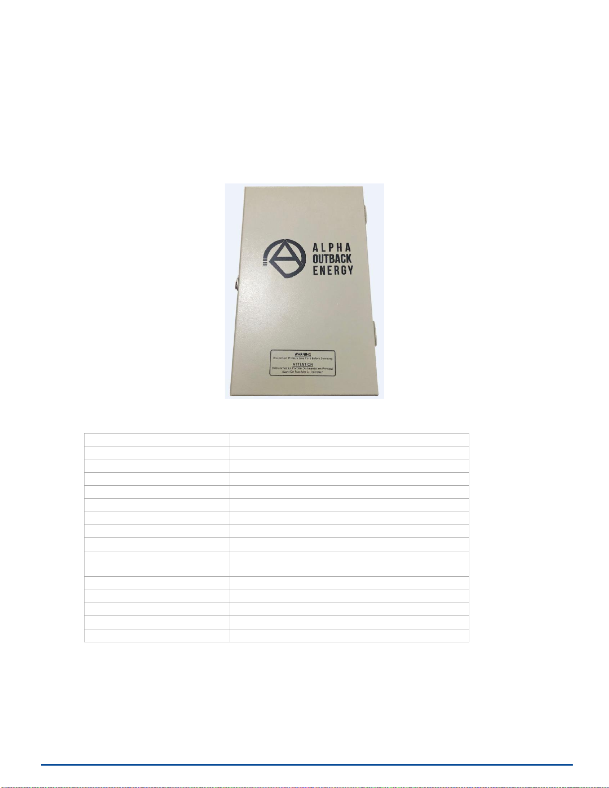
The Alpha and Outback Energy APX2PLUS-615G is housed in powder coated aluminum enclosure
which use metal hardware. All interior and exterior metal parts have smooth surfaces with rounded
corners. There are no sharp metal corners or edges that could cause injury to any personnel.
When properly installed, the entire exterior of the housing is at ground potential and no shock or
electrical hazards exist.
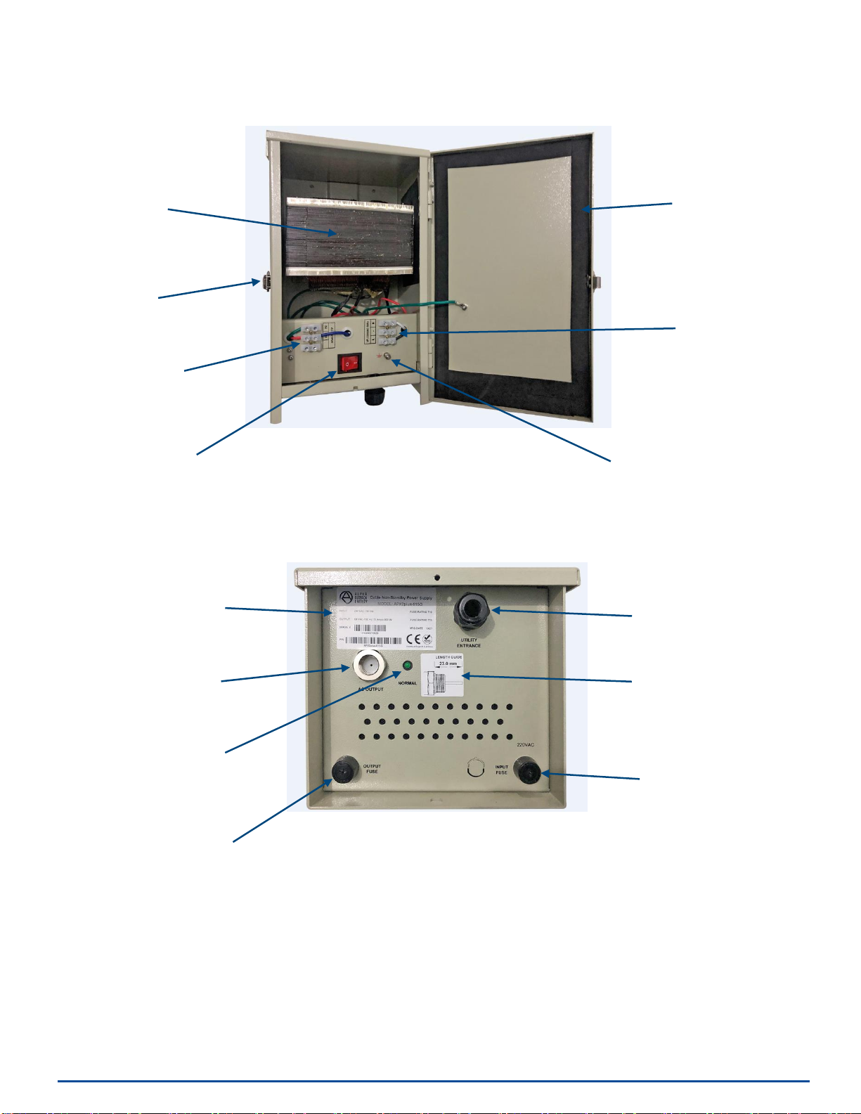
When the housing lid is open for set-up, maintenance, servicing etc., potentially harmful AC voltages
may be present at many contact points inside the housing. Please become familiar with the internal
circuits and the voltages that exit at all points of potential contact before any work is begun.
Field personnel must be aware of these hazards and caution should be exercised to avoid contact with
all contact points throughout the enclosure that are not at direct ground potential (mechanically
fastened to the housing chassis).
MOUNTING:
Mount this product only as described in the installation instructions, otherwise it may fall
causing serious personal injury and/or damage the unit. Use only the bracket supplied with
the product. Do not use attachments not recommended for this product as they may cause
hazards.
SERVICING:
Remove power from this device and refer servicing to qualified personnel under the
following conditions:
1. If the inside of the station has been exposed to rain or water.
2. If the station does not operate normally by following the operating instructions.
Adjust only those controls that are covered by the operating instructions as an
improper adjustment of the controls may result in damage and will often require
extensive work by a qualified technician to restore the unit to its normal operation.
3. If the unit has been dropped or the chassis has been damaged.
4. If the unit exhibits a distinct change in performance.
REPLACEMENT PARTS:
When replacement parts are required, be sure the service technician has used
replacement parts specified by the manufacturer or those that have the same
characteristics as the original part. Unauthorized substitutions may result in fire, electric
shock or other hazards.

Page 4of 8
SECTION 1 PRODUCT DESCRIPTION
1.1 General Description and Function
The Alpha and Outback Energy APX2PLUS-615G is a Cable Network Non-Standby Power
Supply that produces 63VAC Quasi-Square Wave power for use in the CATV plant.
The unit is powered by 230VAC, 50Hz Utility power and can be pole or wall mounted with
the included mounting bracket.
1.2 Specifications
Input Voltage
230VAC (-20% to +15%), 50Hz Sine Wave
Power Factor
0.90 at Full Load
Output Voltage
63VAC 50Hz Quasi-Square Wave
Output Voltage Regulation
+/-5%
Output Current
15 Amps
Output Protection
Current Limited
Output Power
900W
Short Circuit Current
150% of Max. Current Rating
Efficiency
≥ 90%
Dimensions
215 (W) x 338 (H) x 176 (D), mm
8.5” (W) x 13.3” (D) x 6.9” (H)
Finish
Powder Coated
Material
Aluminum
Output Connector
5/8” x 24 Coaxial Connector
Operating temperature
-40°C to 55°C
Humidity
0 to 90% Non-Condensing

Page 5of 8
1.3 Layout
Front View with Door Open
Bottom View
Weather Seal
Input Terminal
Block
Output Terminal
Block
Ferro-Resonant
Transformer
Locking Hasp
Product Label
Utility Input
Cable Gland
5/8” x 24
Coaxial Cable
AC Output
Connector
Cable Connector
Pin Length Cut
Guide
Earth Ground
Bonding Terminal
Power On/Off
Switch
Input Fuse:
10A 250VAC
Ceramic Slow Blow
“Output On”
LED Indicator
Output Fuse:
15A 250VAC
Ceramic Slow Blow

Page 6of 8
Wooden Pole Mounting: Metal/Concrete Pole Mounting:
•Use M12 machine bolts to install the •Use 2 mounting straps to secure
bracket to the wooden pole. the bracket to the steel/concrete
pole.
•Hang the power supply on the bracket •Hang the power supply on the
and fasten the housing bottom to the bracket and fasten the housing
bracket using the M8 seizure hex bolt. bottom to the bracket using the
M8 seizure hex bolt.
SECTION 2 INSTALLATION
2.1 Pre-Inspection
UponreceiptoftheAPX2PLUS-615G PowerSupply inspectthecartonfor any
externaldamage.If damageis presentinspectthePowerSupply exteriorfordamage.
Reportany apparentdamagetotheshippingagentandpointofpurchase.
2.2 Mounting Installation
The Power Supply can be easily mounted on a wooden/metal/concrete pole or on a flat
vertical surface such as a wall using the supplied mounting bracket.

Page 7of 8
WARNING - In order to protect personnel responsible for operation, service
and maintenance of this Power Supply and to protect equipment within the
network, all installation sites MUST be provided with an earth ground bonding
connection to the Power Supply bonding terminal. A reliable ground bonding
connection also helps to protect the Power Supply from damage of high-energy
transients, e.g. lightning strike.
The impedance between the Power Supply enclosure and earth must be 25 Ohms or
less. Soil conditions may affect the grounding system meeting the 25 Ohm
(maximum) resistance specified above. Please contact a local grounding system
expert if required.
AC Output Connection:
Output connection of the power supply is made through the 5/8” x 24 coaxial female
connector located on the bottom panel of the Power Supply.
A mating male cable connector appropriate for the coaxial hardline to be used must have
the center pin prepared as follows:
Screwthemalecableconnector(externalfitting) into the 5/8” female connection.The
centerpinisautomatically seizedby thefemaleconnector.Prepareandattachthecoax ial
hardlinefeeding the HFC plant to the male cable connector as per the manufacturer’s
instructions.
AC Input Connections:
An external servicedisconnect(UL listed)MUST beinstalledbetweentheUtility power
andAPX2PLUS-615GPowerSupply. Thedisconnectdeviceis providedby theuser.Please
consultthelocalsupplier,supplieroftheservicedisconnectandyourlocalutilityfor
specificinstallationinstructionsandguidelines.Allelectricalcodesapply.
Before attempting to connect the input supply wiring, ensure that the disconnect is in the
disconnect (off) position. Using an RMS voltmeter, confirm that no voltage exists at the
disconnect output.
The Utility power connection is made through the Power Supplies cable gland to the
input terminal block. Ensure that no strands of bare wire are outside of the terminal
block. Tighten each terminal screw with sufficient torque to ensure a good electrical and
mechanical connection.
2.3 Electrical Connection

Page 8of 8
2.4 Start Up
Engage the external service disconnect and verify with an RMS voltmeter that 230VAC line
voltage is present at the input terminal block.
Verify that the “Output On” LED Indicatoris lit indicating output voltage is present.
Close the front door of the APX2PLUS-615G and engage the locking hasp. The hasp is
provisioned for an external lock if so desired.
PLEASE SAVE THIS MANUAL FOR FUTURE REFERENCE.
Worldwide Corporate Offices
Headquarter Germany
Hansastrasse 8
D-91126 Schwabach
Tel: +49 9122 79889 0
Fax: +49 9122 79889 21
Mail: info@alpha-outback-energy.com
Eastern Europe
ee@alpha-outback-energy.com
Middle East
me@alpha-outback-energy.com
France and Benelux
fbnl@alpha-outback-energy.com
Spain
spain@alpha-outback-energy.com
Russia
russia@alpha-outback-energy.com
Africa
africa@alpha-outback-energy.com
Alpha and Outback Energy GmbH reserves the right to make changes to the products and information contained in this document without notice. Copyright © 2020Alpha and Outback Energy
GmbH. AllRights reserved.
For more information please visit www.alpha-outback-energy.com
Table of contents
Other Alpha Outback Energy Power Supply manuals
Popular Power Supply manuals by other brands

Kofloc
Kofloc PSK-FB Series instruction manual

Pulsar
Pulsar 54V/8x03A/4x7Ah manual

American Magnetics
American Magnetics 601 Installation, operation and maintenance instructions

Paradyne
Paradyne 7123 installation instructions

velda
velda Ultra Protector User instructions

SECO-LARM
SECO-LARM ENFORCER PH-U1612-PULQ manual